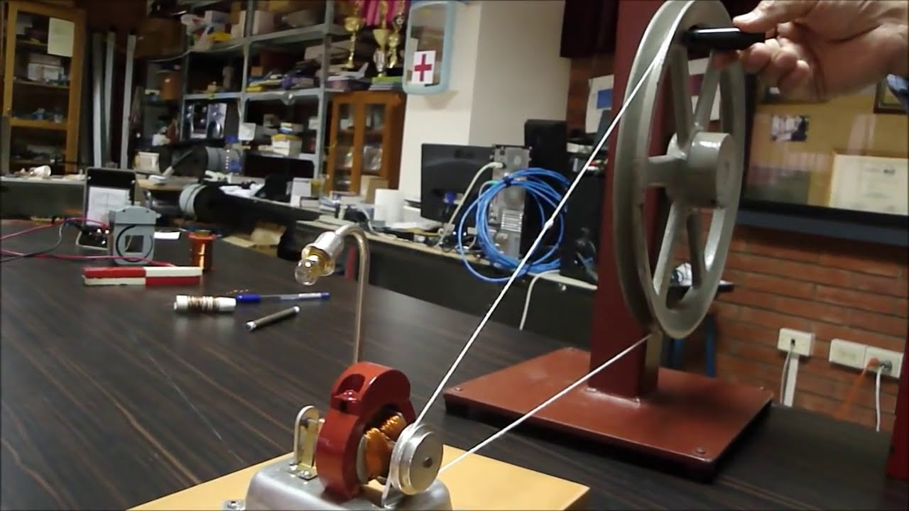
A DC motor can function as an electrical generator when mechanically rotated, converting mechanical energy into electrical energy; in this demonstration, a DC motor generates approximately 30V DC and 6A current (180W) when rotated by hand, demonstrating the principle of electromagnetic induction where mechanical motion induces electrical current in the motor's windings.
Build 180W Free Energy Generator From Old DC Motors
Added:Deep Dive
Faraday's Law of Electromagnetic Induction and the physical principles of how DC motors can run in reverse to generate electricity.
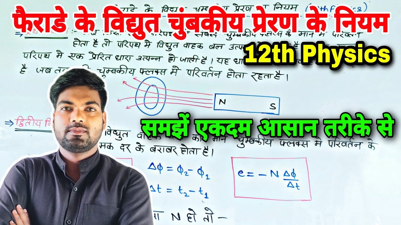
फैराडे के विद्युत चुंबकीय प्रेरण के नियम | Faraday's law of electromagnetic induction | By monu sir
312K
Faraday's Law of Electromagnetic Induction consists of two laws: the first law states that when magnetic flux through a closed circuit changes, an electromotive force (EMF) is induced in the circuit, causing an induced current to flow as long as the flux continues to change; the second law states that the magnitude of the induced EMF equals the negative rate of change of magnetic flux (EMF = -dΦ/dt), where the negative sign indicates that the induced current always opposes the change in flux that produced it, as described by Lenz's Law.
Click to watch →
🎁عيدية طلبة 2026 || جميع رسومات الكتاب المطلوبة
18.9K
This section covers the fundamental principles of electromagnetic induction. Students learn that a changing magnetic field induces an electric current in a conductor (Faraday's Law). The direction of induced current is given by Lenz's Law, which states that the induced current creates a magnetic field opposing the change in flux. Students practice drawing circuits with coils connected to galvanometers, demonstrating how moving a magnet toward or away from a coil produces current in opposite directions. The section also covers eddy currents in conductors, which create opposing forces that resist motion. Students learn to draw diagrams showing the interaction between magnetic fields and conductors, including the generation of opposing forces.
Click to watch →
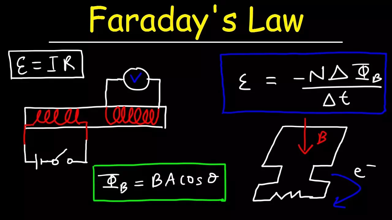
Faraday's Law of Electromagnetic Induction, Magnetic Flux & Induced EMF - Physics & Electromagnetism
968K
Faraday's Law states that a changing magnetic flux through a coil induces an electromotive force (emf) in the coil, expressed as ε = -N(ΔΦ/Δt), where Φ = BAcosθ represents magnetic flux depending on magnetic field strength (B), coil area (A), and the angle (θ) between the magnetic field and the normal to the coil; induced emf can be generated by changing the magnetic field, altering the coil's area, or rotating the coil to change the angle, with more coil loops producing greater induced emf.
Click to watch →
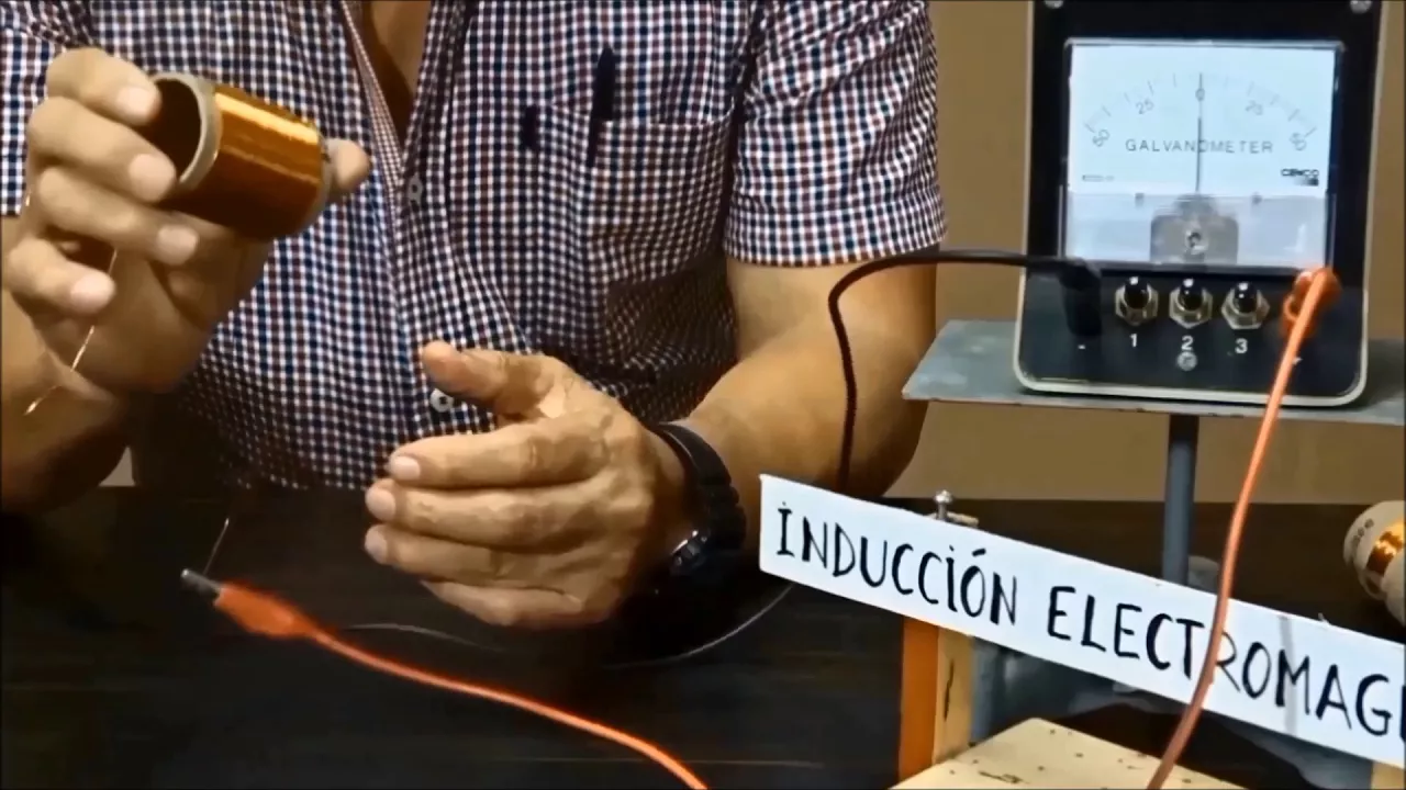
LEY DE FARADAY: CON IMANES Y BOBINAS. La Corriente Eléctrica
106.5K
Faraday's Law states that an electric current is induced in a coil when there is relative motion between the coil and a magnet, with the magnitude of the induced current depending on three factors: the number of turns in the coil (more turns produce more current), the strength of the magnetic field (stronger magnets produce more current), and the speed of the relative motion (faster movement produces more current); this principle forms the fundamental basis for generating electricity in power plants.
Click to watch →
LEY DE FARADAY - LA CORRIENTE ELÉCTRICA- Generador de Corriente
429.3K
Electromagnetic induction, discovered by Michael Faraday in 1831, states that moving a magnet near a coil of wire generates an electric current; the amount of induced current depends on the strength of the magnet, the number of turns in the coil, and the speed at which the magnet moves relative to the coil, forming the fundamental principle behind all electrical generators and power plants.
Click to watch →
Deep Dive
Basic electrical circuit theory, specifically understanding the relationships between Voltage (V), Current (I), Resistance (R), and Power (P = VI).
{311} Relation between Voltage current resistance and power explained
12K
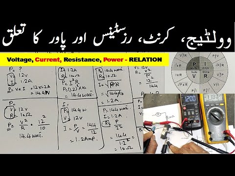
In electrical circuits, voltage (V) is the potential difference that drives electron flow, current (I) is the rate of electron flow measured in amperes, resistance (R) opposes current flow measured in ohms, and power (P) is the rate of energy conversion measured in watts. These four quantities are interrelated through Ohm's Law (V = IR) and the power formula (P = VI), allowing any two known values to calculate the third. For example, with 5V across a 7Ω resistor, the current is approximately 0.715A, and the power is approximately 3.57W.
Click to watch →

#02 Physics : Railway General Science Top 100 Questions | ALP | Group D | NTPC | TECHNICIAN
463
The relationships between power (P), voltage (V), current (I), and resistance (R) are: P = VI, P = V²/R, and P = I²R. These formulas are interconnected through Ohm's Law (V = IR). For example, substituting V = IR into P = VI gives P = (IR)I = I²R, and substituting I = V/R into P = VI gives P = V(V/R) = V²/R.
Click to watch →

UPTET SCIENCE CLASSES 2026 | UPTET SCIENCE PRACTICE SET CLASS | UPTET SCIENCE 2026 | UPTET 2026
127
Using Ohm's Law (V = IR), the following relationships can be derived: V = P/I, V = PR, I = P/R, I = V/R, R = P/I², and R = V²/P. These formulas allow calculation of any electrical parameter when others are known, forming a complete set of relationships for circuit analysis.
Click to watch →

9702/11/O/N/2016|Physics 9702|P1|As Level|Cambridge
1.6K
Three key relationships connect power (P), voltage (V), current (I), and resistance (R): P = VI, P = I²R, and P = V²/R. Given power and voltage, current can be found using I = P/V. Resistance can be found using R = V²/P. For a device rated at 120 W and 12 V, the current is 10 A and the resistance is approximately 1.2 Ω.
Click to watch →

Lec 6 V,I,R,P, VI Relation
133
Voltage is the electrical force that pushes electrons through a conductor, measured in volts; current is the flow of electrons through a circuit, measured in amperes; and power is the rate at which electrical energy is transferred, measured in watts. These three quantities are related by Ohm's Law (V = IR) and the power formula (P = VI), where increasing voltage increases current proportionally, and power equals the product of voltage and current.
Click to watch →
Deep Dive
The First Law of Thermodynamics (Conservation of Energy) to critically analyze claims of 'free energy' and understand that energy must be converted from an input source.

Kuliah Termodinamika I Materi Gravitasi Energi Kinetik dan Potensial
144
The First Law of Thermodynamics states that energy cannot be created or destroyed, only transformed from one form to another. This principle, also called the Law of Conservation of Energy, explains why claims of 'free energy' or 'unlimited energy' are impossible. Energy transformations, such as burning kerosene converting chemical energy to heat, demonstrate that energy is conserved and only changes form. The law applies universally, meaning no device can produce energy from nothing.
Click to watch →

1976: Mr Buckle’s BRINY ENGINE | Nationwide | Weird and Wonderful | BBC Archive
12.3K
The First Law of Thermodynamics states that energy cannot be created or destroyed, meaning you cannot get more energy output than you put in. This principle explains why perpetual motion machines and free energy devices are impossible. The law has been understood since at least the 13th century when inventors attempted perpetual motion wheels, and continues to apply to modern claims of over-unity energy systems.
Click to watch →

A Very Confused Person Tries To Debunk Maths, Einstein, And Thermodynamics
755.8K
The first law of thermodynamics states that energy cannot be created nor destroyed, only converted from one form to another. For example, in a car engine, fuel (chemical energy) is converted to motion (kinetic energy), heat, sound, and other forms. This means you cannot have something for free - energy must come from somewhere.
Click to watch →
The Surprising Truth About FREE ENERGY and PERPETUAL MOTION MACHINES
154.7K
Perpetual motion machines and free energy devices are physically impossible because they violate the laws of thermodynamics: the First Law states that energy cannot be created or destroyed, only converted between forms, meaning you cannot get more energy out than you put in; the Second Law states that entropy always increases, meaning no process can be 100% efficient and some energy is always lost as heat, friction, or vibration. Historical attempts like Bhaskara's mercury wheel and Robert Boyle's self-watering pot failed for these fundamental reasons, and modern claims by inventors like Stanley Meyer and Maxwell Chikumbutso have consistently failed to produce working prototypes despite their promises.
Click to watch →
Free Energy Friday - Ep3 Dirac Holes
3.6K
The first law of thermodynamics states that energy cannot be created or destroyed, only transformed or conserved. In the context of free energy, this means that energy must already exist somewhere in the environment to be extracted. The universe is filled with mass and energy, and this energy can be accessed and utilized without violating conservation laws.
Click to watch →
Deep Dive
How to use a digital multimeter to measure open-circuit voltage and short-circuit current in a power source.

Измерение сопротивления петли фаза-ноль и тока КЗ мультиметром и сравнение с ИФН-200
467.4K
The video demonstrates how to measure loop resistance (phase-neutral) and short-circuit current using a standard digital multimeter and a powerful load device like an electric kettle, instead of specialized instruments. The method involves: (1) measuring the load resistance (27.6 ohms for the kettle), (2) measuring open-circuit voltage (239V), (3) measuring voltage under load (236V), (4) calculating loop resistance using the formula: (voltage difference × load resistance) / voltage under load = 0.35 ohms, and (5) calculating short-circuit current as open-circuit voltage divided by loop resistance = 683A. This DIY method yields results within approximately 5% of specialized instruments like the IFN-200, making it a practical alternative for home electrical testing while emphasizing the importance of safety precautions during electrical work.
Click to watch →

Sabit Cərəyan Mənbələri. EHQ.Tam Dövrə üçün Om Qanunu.Tam Dövrənin F.İ.Ə. DİM 2023 Fizika Test Toplu
20.5K
In a short circuit, the external resistance is zero, so the current is determined only by the internal resistance: I_short = EMF / r. For example, if EMF = 12V and r = 2Ω, then I_short = 12/2 = 6A. This maximum current flows through the internal resistance and can cause heating or damage to the power source. When a circuit is open (switch open), no current flows, so there is no voltage drop across the internal resistance. The voltmeter connected across the power source will measure the full EMF.
Click to watch →

Измерение сопротивления петли фаза ноль и тока короткого замыкания мультиметром.
10K
This video demonstrates how to measure the phase-neutral loop resistance and calculate short-circuit current using only a digital multimeter and an electric kettle as a load, without specialized equipment; the method involves measuring the kettle's resistance, the no-load voltage, and the loaded voltage, then applying the formula R_loop = (U_no_load - U_load) × R_kettle / U_load, followed by calculating I_sc = U_no_load / R_loop, with results validated against a specialized ИФН-200 meter and showing that shorter cable runs yield lower resistance and higher short-circuit currents.
Click to watch →
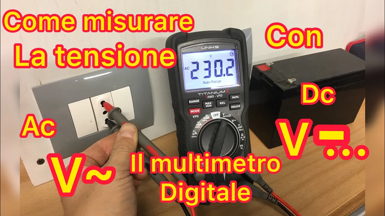
Come usare il multimetro digitale - tester- per misurare la tensione
129K
A digital multimeter (tester) measures electrical voltage by connecting probes to the circuit and selecting the appropriate mode (AC for household outlets, DC for batteries) on the selector dial; for AC measurements, connect probes to the outlet slots without worrying about polarity, while for DC measurements, connect the red probe to the positive terminal and black probe to the negative terminal, ensuring the meter is set to the correct voltage range.
Click to watch →
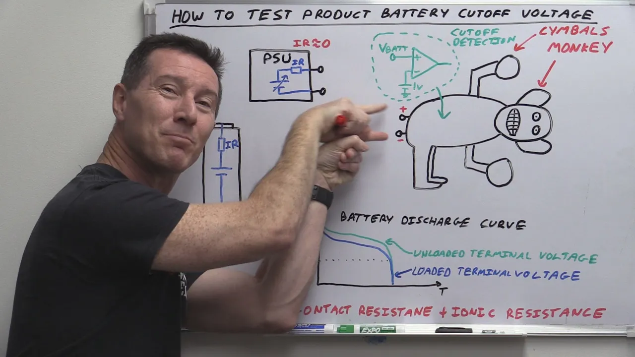
EEVblog #779 - Batteriser: How To Measure Battery Cutoff Voltage
97.6K
Measuring open-circuit battery voltage with a multimeter is fundamentally wrong for determining cut-off voltage. When no current flows, there is no voltage drop across internal resistance, so measured voltage is higher than actual operating voltage. This ignores internal resistance and provides misleading results about remaining battery capacity. The error stems from confusing battery chemistry with electrical behavior—what matters is the terminal voltage under load during product operation, not the open-circuit voltage. This is basic electronics knowledge that should be understood at hobbyist level.
Click to watch →
Prerequisite Knowledge
- Concept 01Faraday's Law of Electromagnetic Induction and the physical principles of how DC motors can run in reverse to generate electricity.
- Concept 02Basic electrical circuit theory, specifically understanding the relationships between Voltage (V), Current (I), Resistance (R), and Power (P = VI).
- Concept 03The First Law of Thermodynamics (Conservation of Energy) to critically analyze claims of 'free energy' and understand that energy must be converted from an input source.
- Concept 04How to use a digital multimeter to measure open-circuit voltage and short-circuit current in a power source.
Subsequent Learning
- Step 01Analyzing generator efficiency and measuring mechanical-to-electrical energy conversion losses (such as friction and winding resistance).
- Step 02Designing and implementing power conditioning circuits, including rectifiers, voltage regulators, and buck-boost converters to stabilize generator output.
- Step 03Understanding thermoelectric cooling and the Peltier effect, which is the scientific principle behind DIY portable refrigeration.
- Step 04Scaling the concept to practical off-grid renewable energy applications, such as micro-wind turbines or small-scale hydro-generators.
Voltage Test
Max Output
Bulb Glow
Voltage Test
12:03Playing Section
- 1
Connect meter to DC mode and wires for measurement.
- 2
Hand rotation yields 3-4.5 volts output.
- 3
Rope rotation spikes voltage beyond 20 volt range.
The Laws of Thermodynamics and the Impossibility of Free Energy
In physics and engineering, the concept of a 'free energy' or 'overunity' generator is a physical impossibility. This concept directly violates the First Law of Thermodynamics, which dictates that energy cannot be created or destroyed, only transformed from one form to another. Additionally, the Second Law of Thermodynamics establishes that any energy conversion process will experience losses, such as heat and friction, meaning the efficiency of any generator is always under 100%. While old DC motors can indeed be repurposed to convert mechanical energy into electrical energy (such as in wind or hand-crank generators), they still require an external, physical power source to spin. They cannot generate self-sustaining electricity out of nothing. Claiming a device generates 'free energy' mischaracterizes standard energy conversion and ignores fundamental physical laws.
Deep Dive
Analyzing generator efficiency and measuring mechanical-to-electrical energy conversion losses (such as friction and winding resistance).

Electrotechnics N6 Hopkinson's back to back Test Example 1 - Efficiency Testing of Dc Machines
3.6K
For the generator, output power P_out = V × I₁ = 200V × 88A = 17,600W. The three losses for the generator are: shunt field copper loss = 500W, armature copper loss = 409.51W, and friction/windage loss = 495.24W. Total losses = 500 + 409.51 + 495.24 = 1,404.75W. Input power P_in = V × (I₁ + I₂) = 200V × 103A = 20,600W. Efficiency η_generator = [(17,600) / (20,600 - 1,404.75)] × 100% ≈ 92.68%.
Click to watch →

EE Comprehensive Exams Lecture 5A: DC Generators
3.1K
For the same generator: (1) EG = VT + Ia × Ra = 250 + 200 × 0.02 = 254 V, (2) PD = EG × Ia = 254 × 200 = 50,800 W, (3) Mechanical efficiency = PD / (PL + mechanical losses + copper losses) = 50,800 / (48,750 + 950 + 2,050) = 98.16%, (4) Electrical efficiency = PL / PD = 48,750 / 50,800 = 95.96%.
Click to watch →

BSPHCL TG-III, Full Technical Syllabus Free | DC Generator Lec-16 | @PrarthanaEducation
702
Mechanical loss includes Friction Loss (brushes and bearings) and Windage Loss (air resistance). Stray loss combines mechanical and iron losses. Losses are classified as constant (iron, mechanical, shunt field copper) or variable (armature and series field copper) based on load conditions. In DC generator power stage: Mechanical input → Iron/friction loss → Developed power (E×Ia) → Copper loss → Output power (V×IL). Efficiency = Output/Input. Mechanical efficiency = Developed power/Mechanical input. Electrical efficiency = Output power/Developed power. Overall efficiency = Electrical × Mechanical efficiency.
Click to watch →
![[전기기기 치트키] 2편. "진짜" 시험에 나오는 것만 뽑았습니다.](https://i.ytimg.com/vi/vIT1t-xfY5k/maxresdefault.jpg)
[전기기기 치트키] 2편. "진짜" 시험에 나오는 것만 뽑았습니다.
45.4K
Efficiency (η) is the ratio of output to input power as a percentage: η = (Output/Input) × 100%. Losses are the difference between input and output. Measured efficiency uses instruments to measure actual input and output power. Calculated efficiency determines losses and compares to input power. For generators, ηg = (Pout / (Pout + Ploss)) × 100%, with input as mechanical power. For motors, ηm = (Pout / Pin) × 100%, with input as electrical power. The key distinction is that generators use output as denominator while motors use input as denominator.
Click to watch →
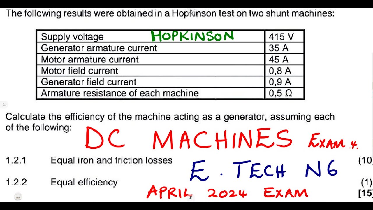
Electrotechnics N6 DC Machines Exam 4 April 2024 - Hopkinson's back to back Test
4.6K
Efficiency (η) = (Output Power) / (Output Power + Losses) × 100%. For generator acting as generator: Output = V × I1 = 415V × 34.1A = 14141.5W. Losses include: shunt field loss (373.5W), armature loss (62.5W), and friction/iron loss (1992.5W). Total losses = 373.5 + 62.5 + 1992.5 = 2428.5W. Efficiency = 14141.5 / (14141.5 + 2428.5) × 100% ≈ 85.296%.
Click to watch →
Deep Dive
Designing and implementing power conditioning circuits, including rectifiers, voltage regulators, and buck-boost converters to stabilize generator output.

1826 What Is MPPT And PWM And What To Do With A DIY Wind Turbine
34.8K
Generators produce AC current that must be converted to usable DC power. The process involves three key stages: (1) Rectification using diodes (4 for single-phase, 6 for three-phase) to convert AC to pulsating DC; (2) Smoothing with capacitors to reduce voltage ripple; (3) Voltage regulation using electronic or electromechanical methods to maintain constant output. Without these steps, the irregular voltage from variable-speed generators would damage connected equipment.
Click to watch →

Sistema de Carga - Curso de Mecânica - #8
28.8K
The rectifier converts three-phase alternating current from the alternator into direct current using diodes (typically 6-9 diodes). The voltage regulator maintains output voltage within 13.8-14.4 volts using pulse-width modulation (PWM), rapidly connecting and disconnecting the rotor 400-600 times per second. Common failure points include burned stator windings, mechanical failures in pulleys and bearings, and rectifier diode failures. Individual diodes can often be replaced rather than the entire rectifier plate, which is more cost-effective.
Click to watch →

Elettronica Go Kart Elettrico con Motore di Lavatrice Costruire Convertitore Buck Boost - Fai Da Te
17.5K
This section details the buck-boost converter design for universal motor rotor control. The buck-boost combines step-down and step-up functionality using four MOSFET switches, capable of producing output voltages both lower and higher than input. The voltage relationship follows Vout = Vin × (D / (1-D)), where D is duty cycle. At 25% duty cycle, output is one-third input; at 75%, output is three times input. Key components include the inductor (44 microhenries), switching frequency, and output capacitors for ripple filtering. Inductor current rises linearly when PWM is high and falls when low, reaching up to 30A. Thermal management through heat sinks is essential for high-current operation.
Click to watch →

004 Making An Emergency Phone Charger
1.5K
Electromagnetic generators produce AC, which must be converted to DC for practical use. A rectifier (diode bridge) converts AC to pulsating DC. A voltage regulator then stabilizes the output to a consistent level suitable for charging devices. The LM2596S regulator can handle 3 amps and accept 3-40V input, outputting 1.5-3.5V. This two-stage process (rectification followed by regulation) is essential for any generator powering electronic devices.
Click to watch →
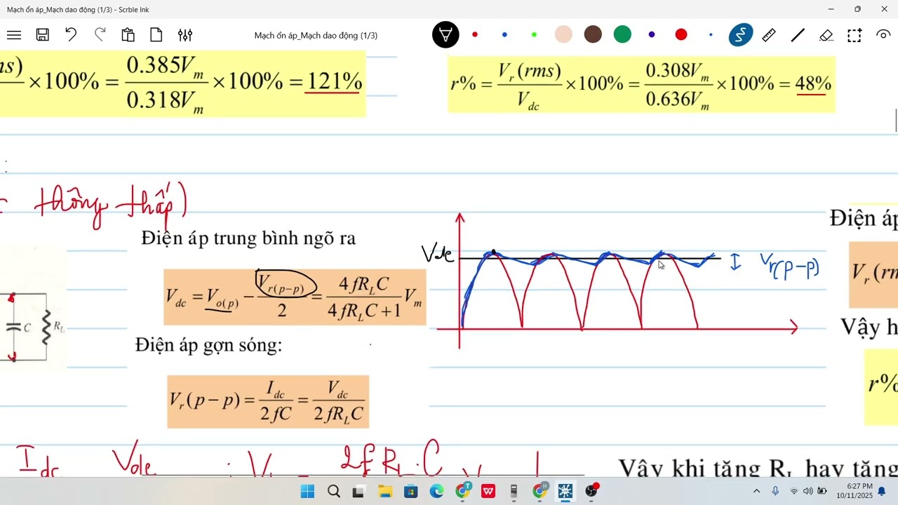
MDT2_Mạch ổn áp + Mạch dao động_11/10
320
A complete power supply system converts 220V AC mains to stable DC through four stages: transformer for voltage transformation, rectifier for AC to DC conversion, filter for smoothing, and voltage regulator for stabilization. Half-wave rectifiers use one diode with VDC = VO Max / π = 0.318 × VO Max and ripple factor of 121%. Full-wave rectifiers use center-tapped or bridge configurations with VDC = (2 × VO Max) / π = 0.636 × VO Max and ripple factor of 48%. Capacitor filters use charging/discharging characteristics to reduce ripple, with larger capacitance providing smoother output. The filtered DC output voltage is VDC = (4 × F × R × L × C + 1) × V Max / (4 × F × R × L × C), and the peak-to-peak ripple voltage is VRPP = IDC / (2 × F × R × L × C). The RMS ripple voltage for triangular waveforms is VRMS = VRPP / 2, and the ripple factor is R% = VRMS / VDC. Voltage regulators maintain stable output voltage through negative feedback. Linear regulators use discrete components (transistors, Zener diodes) or ICs. A regulator consists of four blocks: sample/feedback, reference, comparison, and control. For discrete series regulators, Vout = VZener - VBE, and minimum input voltage is Vin min = VZener + (IC min × R). Two-transistor designs separate comparison and control functions for improved speed. Shunt regulators use parallel transistors to shunt excess current to ground. IC regulators include 78xx series (positive, e.g., 7815 outputs 15V) and 79xx series (negative, e.g., 7905 outputs -5V), requiring Vin between 17.5V and 35V for positive regulators. The LM317 is an adjustable regulator with Vout = Vref × (1 + R2/R1), adjustable from 1.2V to 37V with Vin range of 3V to 40V.
Click to watch →
Deep Dive
Understanding thermoelectric cooling and the Peltier effect, which is the scientific principle behind DIY portable refrigeration.
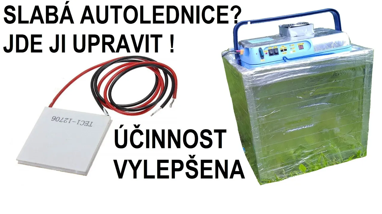
PELTIER - Jak postavit/upravit lednici
84.9K
Peltier thermoelectric coolers are semiconductor devices that transfer heat from one side to the other when a voltage is applied, with typical efficiency around 25-30%, making them suitable for small-scale cooling applications like portable car coolers; effective implementation requires proper heat sinks with adequate surface area ratios (approximately 1:2 between cold and hot sides), quality thermal paste, and sufficient airflow from fans, while avoiding PWM modulation and ensuring continuous operation to prevent heat buildup on the hot side.
Click to watch →

Effet Peltier : Comment ça marche ? - SILISElectronique -
76.5K
The Peltier effect, discovered by French physicist Jean Charles Peltier in 1834, is a thermoelectric phenomenon where an electric current passing through a junction between two different conductors (typically p-type and n-type semiconductors) produces either heating or cooling depending on the current direction; when current flows from p to n junctions, heat is absorbed (cooling), while current flowing from n to p junctions releases heat (heating), enabling applications like portable coolers and microprocessor cooling systems.
Click to watch →

A Thermoelectric Cooler For The Steam Deck! Can We Cool This Hand Held With Science?
129.8K
Thermoelectric coolers, also known as Peltier coolers, utilize the Peltier effect—a thermoelectric phenomenon discovered years ago—to actively transfer heat between two surfaces using electrical current. One side becomes significantly colder while the opposite side becomes hotter. These devices are commonly found in phone coolers, gaming accessories, and portable cooling solutions. The hot side requires active heat dissipation, typically through integrated fans, to maintain cooling efficiency. This technology enables targeted cooling without refrigerants or moving parts, making it suitable for portable electronic devices.
Click to watch →

BUILD YOUR OWN REFRIGERATOR! - SOLID STATE TEC
1.4M
Peltier devices (thermoelectric coolers) are solid-state refrigeration units discovered by Seebeck and rediscovered by Peltier. They consist of two different conductive materials (like bismuth-tin and copper) joined together. When current flows, electrons at junctions must overcome energy barriers between dissimilar metals. Electrons absorb heat at one junction (cooling it) and release heat at another junction (heating it). The process is reversible—reversing current direction reverses heat flow. These devices are lightweight, have no moving parts, operate silently, and can be powered simply by battery. However, they have lower efficiency compared to phase-change systems.
Click to watch →
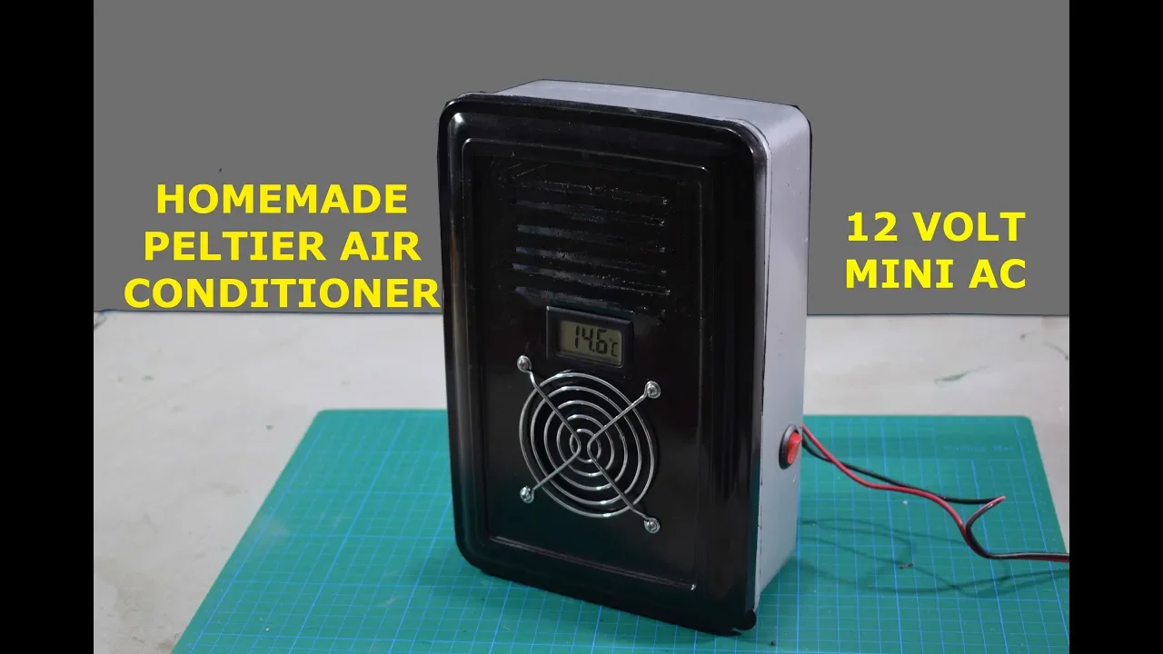
Peltier Air Conditioner - How to make Peltier AC at Home
595.1K
Peltier modules (thermoelectric coolers) work on the principle of the Peltier effect, where applying an electric current causes heat to be absorbed at one junction and released at another, allowing for directional heat transfer without moving parts; when two Peltier modules are connected in parallel with a copper heat sink and cooling fan, they can effectively cool a small enclosed space by transferring heat from the cold side to the hot side, making them suitable for portable mini air conditioning units.
Click to watch →
Deep Dive
Scaling the concept to practical off-grid renewable energy applications, such as micro-wind turbines or small-scale hydro-generators.

Micro Wind Turbines... Are They Worth It? (Off Grid Solar)
925.4K
Micro wind turbines are generally not worth installing for small-scale off-grid power generation because they require extremely high wind speeds (often exceeding what's available in most regions), need towers over 65 feet tall to capture consistent winds, require expensive additional equipment like rectifiers and diversion loads, and involve ongoing maintenance costs; solar panels are a more reliable, cost-effective, and low-maintenance alternative for supplemental power.
Click to watch →

Working home made hydro Generator/ Runs two refrigerators free electricity
353.4K
A homemade micro hydro generator can be constructed using a large-diameter generator (22 inches) with 28 magnets and 28 coils of number 15 wire, producing approximately 12 amps at 30 volts (around 360 watts) when spinning at 170 RPM, sufficient to power two refrigerators; the direct-drive design eliminates the need for pulleys and transmissions, making it low-maintenance with grease required only once annually.
Click to watch →
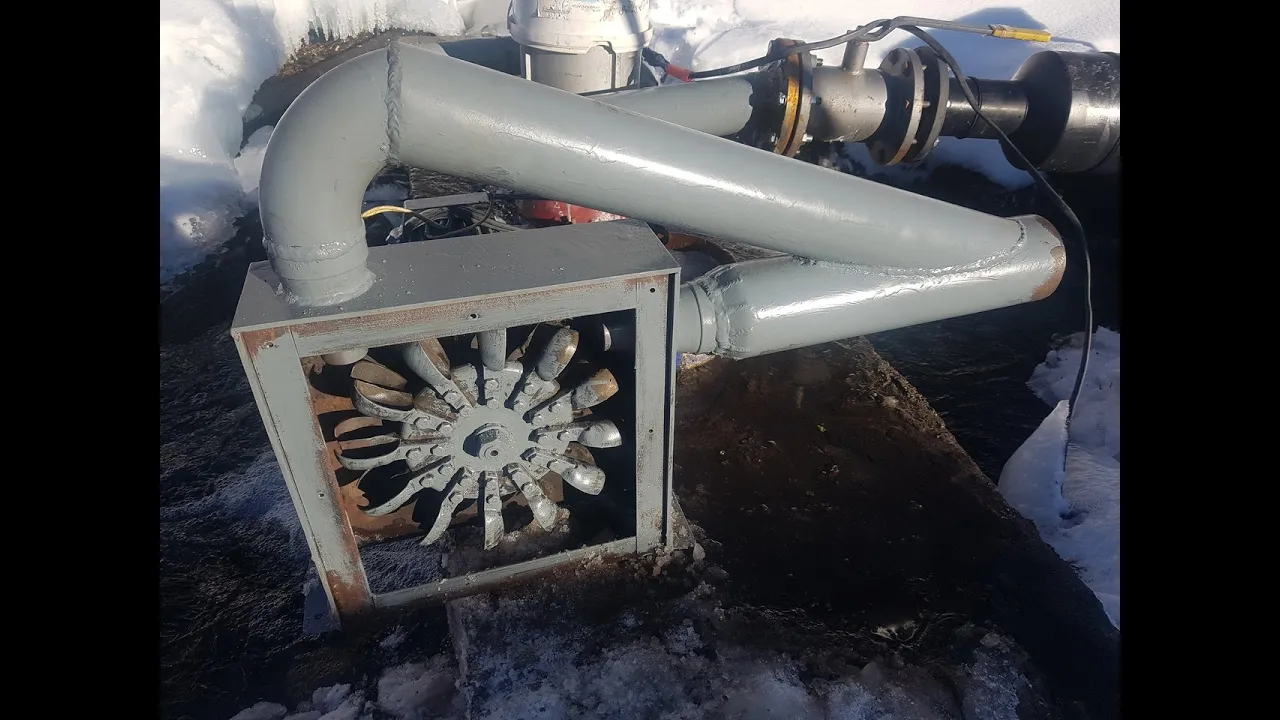
Обзор турбин и генераторов для микро и миниГЭС, нашего и китайского производства.
336.2K
This video explains that four main types of hydro turbines are used in industry: Pelton, Francis, Kaplan, and Banki (cross-flow) turbines, with the Banki turbine being particularly suitable for low-head applications (as low as 3 meters) and capable of being manufactured in home workshops using simple materials like round pipes and sheet steel. The video demonstrates that while Chinese-made turbines are cheaper, they often suffer from poor quality, unbalanced construction, and exaggerated power ratings, whereas properly designed turbines with synchronous generators and appropriate speed reduction systems (4:1 ratio) can achieve reliable power generation with efficiencies around 60-70%. Key considerations include proper bearing systems, seal materials (graphite/ceramic for abrasive water), and the importance of matching turbine speed to generator requirements for efficient power conversion.
Click to watch →

Membuat Pembangkit Listrik Tenaga Air Sederhana
681.9K
This video demonstrates the complete process of building a simple micro hydro generator using recycled materials. The construction involves cutting a plastic bottle into four identical pieces to serve as turbine blades, preparing an old CD as the base by cutting along marked lines, gluing the bottle pieces onto the CD, installing bottle caps as bearings, drilling a chopstick through the caps to create an axle, and connecting the turbine to a dynamo. The final assembly is mounted on a wooden base. The video shows how water flow through the turbine blades causes rotation, which generates electricity through the dynamo.
Click to watch →
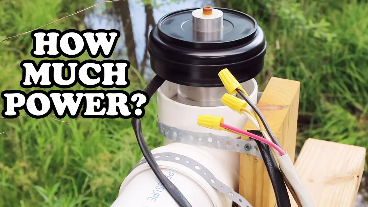
POWER reading on the 4 inch hydro turbine
123.5K
A 4-inch micro hydro turbine generates approximately 17-19 watts at 12.7-12.8 volts when properly connected to a rectifier and charge controller, demonstrating that while such small-scale hydro systems can produce usable power, they typically generate insufficient voltage (below 14V) for practical applications without modifications like increasing the down pipe length or upgrading to a larger pipe size to enhance water flow and rotational speed.
Click to watch →
Voltage Test
Max Output
Bulb Glow
Voltage Test
12:03- 1
Connect meter to DC mode and wires for measurement.
- 2
Hand rotation yields 3-4.5 volts output.
- 3
Rope rotation spikes voltage beyond 20 volt range.
The Laws of Thermodynamics and the Impossibility of Free Energy
In physics and engineering, the concept of a 'free energy' or 'overunity' generator is a physical impossibility. This concept directly violates the First Law of Thermodynamics, which dictates that energy cannot be created or destroyed, only transformed from one form to another. Additionally, the Second Law of Thermodynamics establishes that any energy conversion process will experience losses, such as heat and friction, meaning the efficiency of any generator is always under 100%. While old DC motors can indeed be repurposed to convert mechanical energy into electrical energy (such as in wind or hand-crank generators), they still require an external, physical power source to spin. They cannot generate self-sustaining electricity out of nothing. Claiming a device generates 'free energy' mischaracterizes standard energy conversion and ignores fundamental physical laws.
Faraday's Law of Electromagnetic Induction and the physical principles of how DC motors can run in reverse to generate electricity.
Basic electrical circuit theory, specifically understanding the relationships between Voltage (V), Current (I), Resistance (R), and Power (P = VI).
The First Law of Thermodynamics (Conservation of Energy) to critically analyze claims of 'free energy' and understand that energy must be converted from an input source.
How to use a digital multimeter to measure open-circuit voltage and short-circuit current in a power source.
Analyzing generator efficiency and measuring mechanical-to-electrical energy conversion losses (such as friction and winding resistance).
Designing and implementing power conditioning circuits, including rectifiers, voltage regulators, and buck-boost converters to stabilize generator output.
Understanding thermoelectric cooling and the Peltier effect, which is the scientific principle behind DIY portable refrigeration.
Scaling the concept to practical off-grid renewable energy applications, such as micro-wind turbines or small-scale hydro-generators.
41.9K views320likes16:52@mrelectron_alternatorOriginal Release: 2024-12-25
[Music] [Music] n [Music] [Music] [Applause] [Music] he [Music] [Applause] oh [Music] [Music] [Music] [Music] oh oh [Music] [Music] [Music] n [Music] [Music] that for a [Music] [Music] oh [Music] [Music] [Music] [Music] oh [Music] [Music] [Music] [Music] aah [Music] [Music] [Music] [Music] [Music] oh oh oh oh oh oh [Music] oh [Music] oh [Music] he [Music] [Applause] [Music] [Music] [Music] let's point the meter towards 20 volt DC mode okay and connect these two wires okay so the wires have been connected keep watching the display screen yeah will keep it like this okay simple hand rotation 3 volts 4 volts 4.5 volts yeah now let's do some rope [Applause] rotation okay keep watching the display screens W the voltage was more than 20 volts that's interesting let's do the test [Music] again seems like it has a 24 volts motor keep watching the display screen 31 volts DC that is very nice once again let's see if I can take it even higher okay yeah 31 volts was the maximum I could do let's measure the current [Music] now so guys guys keep watching the display screen wo 5.69 amp now the motor is very powerful it is generating somewhere around 5.69 I'll take it as 6 amp if I could just rotated a little harder so 6 amps and 30 volts so 180 W okay so guys I'm going to try once again and a little more harder let's see if I can generate more ampers okay keep watching the display screen so guys as you saw that I generated 6.10 amps with rope rotation that was really high current so now I'm going to test this 12vt car indicator bulb and I'm going to Glow this with this generator okay so the terminals have been connected let's W the road yeah let's keep it like this next a lot of love and thanks to my paid members for their additional Support also a big recommendation for all to check my 3D prints page and my socials for even more fun links are in the description and lastly subscribe this Channel and share my videos with your friends for a stronger Community best regards electron
Up Next

7:22
How to Charge a Supercapacitor Safely with a Car Battery Charger
@BackyardAmusement
159.5K views•2012-05-10

12:54
Triumph of Orthodoxy Icon: Byzantine Art & History Explained
@BenCallan
2.1K views•2024-08-06

9:49
FastAPI vs Flask vs Django: Choosing the Right Python Web Framework
@TechWithTim
302.5K views•2024-05-26

1:42
Game of Thrones Opening Credits: A Cinematic Analysis
@gameofthrones
46.3M views•2011-04-18
Related Study Plans & Knowledge Roadmaps
Structured learning paths in General & Interdisciplinary Studies
general-studies
Elevator Engineering: History, Physics & Cities
01From Hoists to Safety Brakes: The Dawn of Vertical Lift
02Hydraulic vs. Traction: The Engineering Physics of Elevators
03Modern Speed, Safety, and Algorithms
+ 2 more learning modules
12h5 modules
Explore Roadmap
general-studies
Rubber: Material Science, History & Geopolitics
01Origins of Natural Rubber & Mesoamerican History
02The Chemistry of Natural Rubber & Vulcanization
03The Geopolitics of the Rubber Boom & Colonization
+ 2 more learning modules
12h5 modules
Explore Roadmap
general-studies
Containerization: Evolution, Logistics & Trade
01Ancient Trade & Bulk Cargo: Amphorae to Barrels
02The Industrial Revolution & Cardboard Packaging
03The Containerization Revolution: Malcom McLean
+ 2 more learning modules
12h5 modules
Explore Roadmap
general-studies
Textile Tech: Evolution, Labor & Global Impact
01Pre-Industrial Textiles: Handloom & Cottage Industry
02Mechanization: The Spinning Jenny to the Power Loom
03The Factory System & Global Labor Transformation
+ 2 more learning modules
10h5 modules
Explore Roadmap