





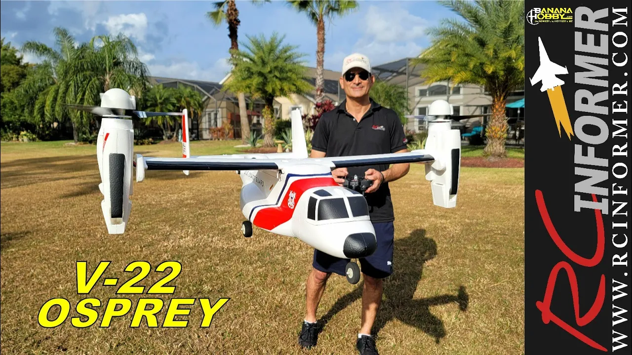














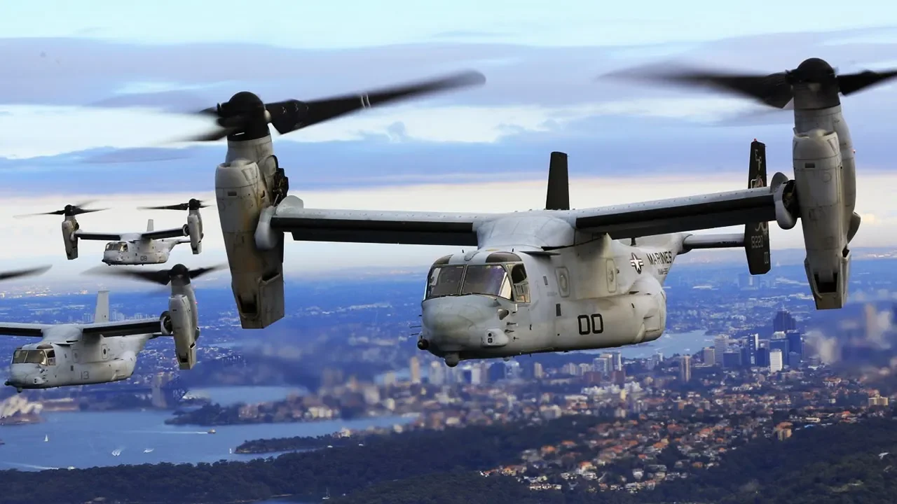




This video documents the complete process of building a scale model of the V22 Osprey tiltrotor aircraft, covering the evolution from a simple freely-hinged rotor head system to a more sophisticated servo-actuated motor pivot design, followed by the fabrication of a lightweight 3D-printed fuselage using specialized materials and techniques, ultimately demonstrating the challenges of achieving stable flight in a VTOL aircraft including center of mass management and transition dynamics.
V-22 Osprey Twin-Rotor Aircraft: Rotor Head Design and Testing
Added:Fundamental helicopter aerodynamics, specifically how a conventional swashplate controls cyclic and collective pitch.
Basic principles of mechanical vibrations, resonance, and damping in rotating machinery.
The physics of VTOL (Vertical Take-Off and Landing) aircraft and the transition mechanics between thrust-borne and wing-borne flight.
An introduction to servo-actuation systems and feedback control loops in aerospace engineering.
Advanced aeroelasticity and rotorcraft aeromechanics, focusing on whirl flutter in tiltrotors during high-speed flight.
Flight control system (FCS) law design, specifically addressing the complex pilot-in-the-loop transition phase.
Structural fatigue, vibration isolation, and maintenance engineering challenges unique to tiltrotor military aircraft.
Comparative study of modern tiltrotor and tilt-wing variants, such as the Bell V-280 Valor and future eVTOL designs.
4.3M views105.2Klikes22:12Original Release: 2022-12-08
part one of this project covered the building and testing of a two rotor aircraft that used 3D printed helicopter rotor heads for control these rotor heads were simple by Design with each blade being freely hinged at the Hub and with some precise motor movements they were able to provide sufficient control to keep the aircraft in the air however it didn't fly first time due to some vibrations with the frame but this was fixed with a stronger wingspar and redesigned motor mounts I then bought these slightly larger blades which are a bit longer in length and they're also completely unbranded in the hope that these will provide more thrust because once we add the fuselage to this thing it's going to weigh quite a bit more but this brought back the vibrations and I think the cause of these vibrations were more serious than I first realized from this slow-mo it seems the small vibrations caused by the blades pivoting causes the frame to flick slightly which is then fed back into the rotor head causing crazy unwanted blade pitch movements these extreme blade angles then cause unwanted load on the motor which then amplifies a vibration to the point where the whole roads ahead rapidly loses lift bear in mind these vibrations are bending this 20 millimeter carbon fiber tube like it's an uncooked spaghetti and these tubes are very strong I could go back to the old blades but if such a small change in the blades causes such a drastic change in performance then I hate to think what would happen once I get the fuselage on this thing for this reason I started designing an actual helicopter rotor head with a swashplate and linkages but whilst developing this I received an email from the original designer of this freely hinged rotohead system if you haven't seen my older video on the swash playlist helicopter the original idea was invented by a guy called Jimmy as part of a research project at the University of Pennsylvania and his motor controller was developed by his friend Matt much has since developed this motor controller further as part of his business vertic and he's actually designed his own freely hinged roads ahead system that uses a single Central hinge instead of one hinge per Blade the clear advantage to this is obviously it's simpler having less hinges in the rotor head but more importantly to my specific use case is that all of the blades are fixed together let me show you why this is important imagine this is the roads ahead and all three blades are evenly spaced apart by 120 degrees the center of mass should be in the center of the rotor head meaning it's perfectly balanced and when the motor wants to create a control output it either accelerates or decelerates to cause the blades to lead or lag in an Ideal World the rotor head should stay balanced as all the blades will swing by equal amounts but if there is a slight variation in hinge friction or one blade experiences more drag than the other they might lead or lag by different amounts which will shift the center of mass away from the axis of rotation causing an imbalance and therefore a vibration so having all these blades fixed together will hopefully remove the vibrations I'm getting and Matt also told me that he successfully tested a three-bladed version of this rotor head with a single Central hinge so with this information I have to build my own this rotohead has a central hinge at 45 degree angle which means when the motor accelerates or decelerates the blade in line with the hinge will change an angle of attack but the other two blades will actually move up or down this looks a little odd when rotating as one blade maintains the same planar rotation but the other two seem to follow a different plane in rotation once on the aircraft it was clear that the previous vibrations were gone which was very promising however it doesn't seem to have much control so the aircraft could only hover for a short period before pitching over and crashing but then Matt showed me another road ahead he's been working on which has the same Central 45 degree hinge as well as another horizontal hinge which means the rotor head can tilt in any direction almost like a universal joint but because of the 45 degree hinge it can still be controlled by the motor speed to Vector the thrust of the blades I found this fascinating that adding a couple of hinges to the rotor head can cause this thrust vectoring effect by simply adjusting the motor speed so of course I have to build my own this is very similar to the previous design but features the extra horizontal hinge through the center and what's interesting is this pivot Direction works fine due to the horizontal hinge but because of the 45 degree hinge to get it to Pivot left and right the blades have to twist side to side and it's this exact movement in reverse that will be used to control the thrust vectoring when mounted on the motor it only requires a small amount of motor pulsing to get the rotor to Pivot which is really cool to watch also because of the reduced vibrations of this rotor head I removed the bulky motor mounts and went back to the 14 millimeter Wings bar to save weight but how does it perform in the air not great after lots of tuning and tweaking of the gyro stabilization it wasn't getting much better but then I'd have thought what if I turn the gyro stabilization off my theory was that the gyroscopic stability of the rotor would tend to stay in position as the aircraft would rotate so is this fighting the electronic gyro stabilization the fact this thing flies with no stabilization on the pitch axis is really interesting and it's something I never considered would be possible the only issue is it relies completely on the position of the rotor blades to keep it stable so if a gust of wind causes the blades to adjust their angle the whole aircraft will follow ultimately I have to make a decision between are we building a strange two-rotor test vehicle or are we trying to build a v22 Osprey scale model and from the title of this video I think you know the answer I really wanted to hold on to this freely hinged rotohead system but in reality it's not feasible for this application the final rotor head was the closest to success but because it's essentially a Thrust vectoring design this can be achieved with a Servo actuated motor pivot and a server actuated motor pivot has the advantage of being able to be locked in position during forward flight I'm sure I could spend a few more weeks or months trying to tune this road to to perform as well as Matt from vertic has done with his but I also feel like that's following the sunk cost fallacy so I removed the hinge rotor heads and have gone with a simple Servo actuated motor pivot which because these will only tilt about 20 degrees in either direction I can use a small Servo with a three to one gear ratio then there will eventually be a large Servo in the center of the frame to rotate the whole Wings bar so this isn't just far simpler electronically but it's also lighter as it just requires these small servos to provide all the control for hover removing both the thicker Wings bar and one of the large tilt servos and when the aircraft transitions to forward flight these small servos will keep the motors in a fixed position essentially just acting as regular aircraft propellers I think it's probably time we move on to the fuselage portion of this project which I gave a little teaser to in the last video the plan is to 3D print the fuselage using a material called lightweight PLA and some unique design methods to save weight this lightweight material Foams up when it is 3D printed and weighs 40 as much as a regular 3D print but the issue with this material is the expansion caused by the foaming process leaves behind some residue if the printer nozzle is lifted away from the part to get around this the model needs to be designed so the printer can create the part without lifting the nozzle I briefly covered this in my previous vtop project and I created a short tutorial over on my second Channel but that was for just a simple Wing shape so how will it work for something more complicated like this fuselage I first started by creating a number of sketches in CAD to follow the profile of the real Osprey which took quite a bit of time to get right but when combined together ends up looking somewhat like the real thing I then created another fuselage that is slightly smaller which will be important in a second from this I can start cutting the reinforcement ribs that will help the fuselage keep its shape currently this would simulate a regular 3D print infill which fills the whole part but for this application it's only needed around the outer skin so I can use a smaller fuselage to subtract all the inner ribs leaving us with the skeleton frame the final step is to remove these ribs from the solid fuselage model as this will trick the printer into printing the part without lifting the nozzle if we were to model the fuselage as a shell and add solid ribs inside the printer will have to lift the nozzle every time it creates a new rib but if the fuselage is a solid model and we cut the ribs out of it the printer will draw each layer without lifting the nozzle creating a clean lightweight part also this is a new version of lightweight pla from colorfab that is able to withstand higher temperatures as I've previously had 3D printed Wings melt in the sun unfortunately this is the perfect color for the Osprey you may notice there is a combination of large and small ribs spanning the inside of the fuselage and that's because I ran a lot of test prints to figure out how I can keep these parts as light as possible whilst also maintaining a strong outer shell here's just some of the prototypes I've printed whilst designing this thing like this one which has like this one which has a high density of very small ribs which holds the skin quite well there's also quite bendy and and flexible then there's this one which has a lower density of larger ribs which is quite a bit stronger but the ribs don't support the skin very well so it flexes between the ribs so this is the final design where it's a combination of the two so there's a high density of thin ribs to maintain the strength of the skin and then a low density of larger ribs to create the general strength of the fuselage so after about four days of printing I now have all the parts ready to glue together which I used regular CA glue or sometimes referred to as super glue which was a bit of a pain as it dries quite fast the fuselage is designed so it's glued together in three pieces the nose a midsection and the tail which will eventually be held together with magnets I then need to remove the wings bar and motors from the frame to install it in the fuselage which is done by sliding the carbon fiber skids into these rails printed into the design once installed I need to cut an opening in the print where the wing will be mounted because this hole couldn't be designed into the model as it's required to print the part using vars mode now the wires can be plugged back in and the wingspar and Motors can be remounted to the frame with access at the front and rear to tighten the required bolts I can then slide the tail section onto the skids to check how it fits as well as attaching the nose and it's really starting to look more like the full scale model all it needs is a few magnets to hold the parts in position I then printed the horizontal stabilizer and elevator using the same lightweight material and design methods to create the hinge for the elevator I chose to cut small strips of rubber sheet that can be glued into this pre-printed slot I was tempted to 3D print an actual hinge pivot for the control surface but this rubber hinge is far easier to manufacture and is still strong yet flexible then the elevator Servo can be glued to the underside which will be hidden inside of the fuselage once mounted but first the Rudders must be glued onto the tips of the horizontal stabilizer and as you can probably guess these were also 3D printed and the whole tail assembly can now be be glued onto the fuselage now it's time to cover up the motor mounts with some scale engine sales and these things are huge just like the real thing which is great for hiding all the messy wiring and they are fixed in position with these glued on brackets as well as some magnets to attach the two halves together leaving just the top of the motor and propeller sticking out also because the motor pivots independently to the engine to sell when hovering the thrust vectoring won't be tilting in the cells back and forth hopefully keeping the aircraft looking scale so before I build the wing it's probably a good time to test if this thing will still hover with the added fuselage the propellers did vibrate a little to the start as the blades were folded slightly for transport but they soon straightened out and the aircraft lifted off the ground easily to be honest I'm surprised at how well this thing flies it's actually more stable with the fuselage attached which is probably because the added weight and inertia dampens the movements I haven't done any tuning since adding the fuselage so it could be a little better but it's definitely a good start and I'm also glad I moved away from the older rotor heads as this system is far simpler and when hovering it's almost impossible to tell that the rotors are tilting due to the stationary engineer cells the next step of this build is to add a tilt mechanism and Wing to the Osprey but first let me show you some interesting mechanisms you can build yourself from kiwico kiwico makes Hands-On projects for kids that are designed to be much more than just a toy as they help teach science and engineering to spark curiosity and creativity I've always been a fan of making or doing things to learn and these kits are an excellent way to get going like this kit where you can build your own lock which requires an actual key to open everyone knows how to unlock a door but do you know how they work inside the design and quality of these kits are just amazing and they're not only educational but also good fun and with everything you need being supplied within the box there is no need to buy anything extra which I think makes for an excellent Christmas gift and trust me completing a project that actually works is the best feeling and you can experience this too by going to the kiwico link in the description to get your first month with kiwico for free so definitely only go and check them out before building the wing we need a method of tilting the motors for transition as they are currently fixed in the vertical position so I removed the fixed Wings bar mount and replaced it with a 3D printed Mount that will hold the Tilt mechanism I chose to use a Servo operated gear system for this tilt as it needs a lot of torque to tilt both Motors simultaneously so these Bethel gears give the servo a three to one ratio where the servo rotates 270 degrees to tilt the wing spark from horizontal to Vertical the server I used is a cheap one I found on Amazon that's designed for radio controlled cars and apparently can live 20 kilograms at a one centimeter radius so about two newton meters of torque but with the gear ratio this is tripled to about 6 newton meters for the aerofoil I chose to use a NACA 6412 because its profile is large enough to fit the wings bar and it's capable of producing a high coefficient of lift before stalling as this aircraft is getting pretty heavy so we need as much lift as possible once 3D printed I can mount the aileron servo inside and glue all the wing sections together which I still haven't improved my gluing skills but I'm hoping to clean some of it off later to fix the wing to the fuselage I didn't want to use glue as I might need to access the Tilt mechanism and other electronics so I made this midsection that simply rests on top of the fuselage then when I slide the wing sections onto the spa it holds the midsection in place and the angle of the wing is supported by the top of the fuselage pressing against it I then remounted the engine the cells and checked if the Tilt mechanism was still working finally we can add the ailerons which work the same way as the elevator by using rubber strips as the hinge now it's time to see if it still hovers it definitely requires a lot more throttle to hover with the wing attached as a large portion of the airflow from the propellers is being blocked by the wing and this is why the ailerons are in their Max downward position to reduce the horizontal Wing area oh and one small tip don't fix an aircraft fuselage together with magnets luckily I thought this might be an issue so printed these clips to clamp the parts together so weighing in at a little over 2.2 kilograms with a one meter wingspan and more panel gaps than a Tesla this thing is ready for a test flight right so today is the day to see whether this thing flies or dies nothing left to do but fly this thing I'm going to take off very quickly and transition to Ford uh half forward fly very quickly just so that we get some uh air under the wings okay okay that's not half bad it's cruising at much lower throttle than when it was hovering I didn't want to spend too much time hovering because battery doesn't last very long okay okay this is actually this is flying at much lower throttle than a hover which is nice uh coming in for another pass that looks amazing so smooth do one more turn and then we'll bring it into land wow wow wow I can't believe this is flying I'm gonna put full flaps down now and then full transition mode that's now in Hover mode okay nope that's not good that's not good okay right so basically what happened is when I flick the uh back to hover mode because the Motors shift backwards a lot the uh it suddenly becomes extremely tail heavy when it's like that see how far the motors are forwards actually wait half transition mode so the motors are there then when I flick into hover mode it suddenly becomes a lot more tail heavy because it shifts the center of mass quite far back right I've replaced the battery ready for test flight number two let's try and get some forward flight action here transition to half forward flight flaps up to halfway get lots of altitude I'm gonna transition now thank you okay it does not like that whoa okay uh that's probably extremely hard to see on the GoPro but I was like Full Throttle and it wasn't climbing at all okay we're really high get ready to transition in three two one it is flying no it doesn't like that yeah um it is not like that at all right let's bring it in for landing let's try not get this Old Tail heavy again I'm gonna try and slow it down enough like this full flaps down and then last second nope nope oh okay yeah this is um that transition back to a hover is absolutely awful and I'm not sure how to get around it it just it just pitches up instantly as the center of mass shifts back I gave it a few more test flights as I had a few spare batteries but it only seemed to fly well in the half transition mode I think this is because it has enough AirSpeed under the wing to reduce the load on the motors but still using the motors to produce lift allows it to fly at a manageable speed the center of mass shift from the motor's tilting is still a major issue for both transitioning back to a hover and also forward flight as when the motors are in the horizontal position the aircraft is extremely nose heavy a simple fix for this could be to add a counterweight to the motor pods to balance the weight of the motors but this thing is already heavy enough so I think a better solution will be to design a weight shifting system that slides the battery back and forth depending on the motor position I would also like to add some more scale features to the design like Windows and maybe undercarriage but for now I think I'm going to keep this as a model for my workshop and enjoy flying my previously built high performance veto
Up Next
9:06
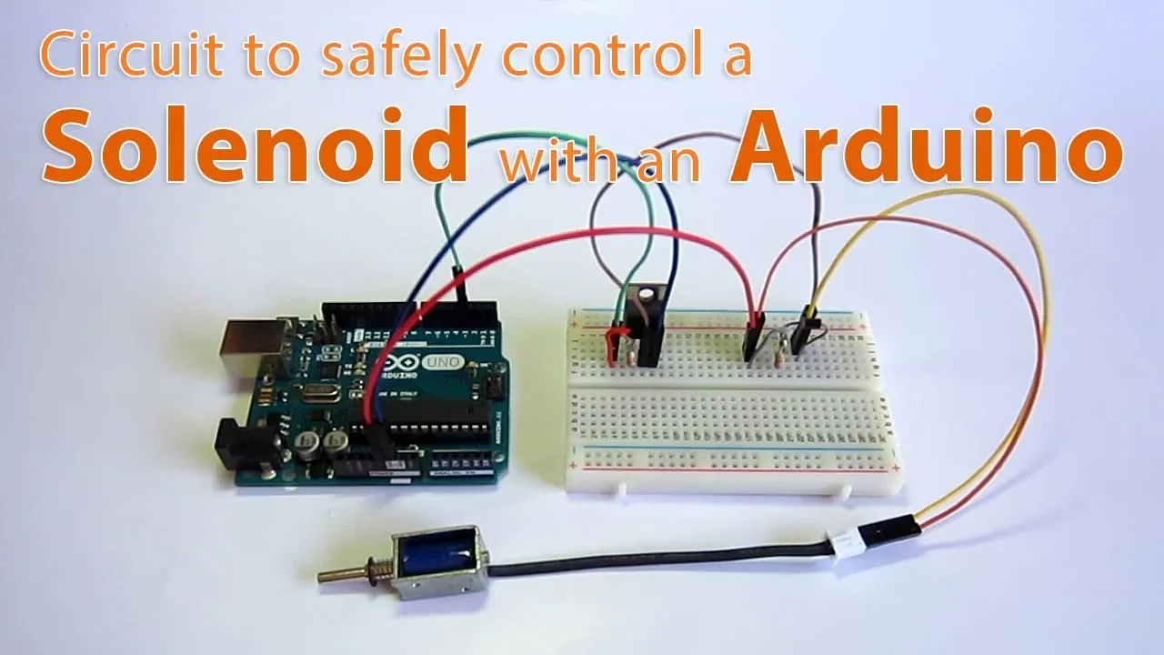
Arduino Solenoid Control with Transistor and Diode
@jomirife
73.5K views•2019-12-05

30:32
Ultrasonic Transducers: Resonant Frequency Measurement and Horn Design
@imajeenyus42
229.9K views•2017-02-22

8:14
Regenerative Braking Efficiency in Electric Bikes: A Quantitative Analysis
@TomStantonEngineering
147.7K views•2017-11-30

33:39
How a Student's Question Saved a NYC Skyscraper from Collapse
@veritasium
22.8M views•2025-04-26
Related Study Plans & Knowledge Roadmaps
Structured learning paths in Engineering
engineering
Building Acoustic Levitators: Physics & Arduino
01The Physics of Sound and Standing Waves
02Piezoelectric Transducers and H-Bridge Drivers
03Arduino Programming: Generating 40 kHz Signals
+ 2 more learning modules
14h5 modules
Explore Roadmap
engineering
Building Peltier Cloud Chambers: Particle Tracks
01Cosmic Rays & Cloud Chamber Physics
02Thermoelectric Cooling (TEC) Fundamentals
03Custom Liquid-Cooling Loop Design
+ 2 more learning modules
18h5 modules
Explore Roadmap
engineering
Yagi-Uda Antennas: Modeling, Build & VNA Test
01Introduction to RF and Antenna Fundamentals
02Yagi-Uda Antenna Design Principles
03Antenna Modeling and Simulation in 4NEC2
+ 2 more learning modules
18h5 modules
Explore Roadmap
engineering
ECG Monitor Design: Op-Amps, Filters & Noise
01Electronics & Breadboard Basics
02Op-Amps and Instrumentation Amplifiers
03Bioelectricity and ECG Fundamentals
+ 2 more learning modules
18h5 modules
Explore Roadmap