![#2.1 Práctica: Instrucciones Básica [ pinMode, digitalWrite, delay ] - Curso Arduino 💻](https://i.ytimg.com/vi_webp/s7Eg6BECNbI/maxresdefault.webp)
![Arduino Programming Series - Tutorial 08 | Digital Input/Output Functions [in Hindi]](https://i.ytimg.com/vi/vuIWHFFzSHg/maxresdefault.jpg)




























![Lesson 3-3 [Sensing and Actuation] Actuators](https://i.ytimg.com/vi_webp/5OkUulJebvE/maxresdefault.webp)
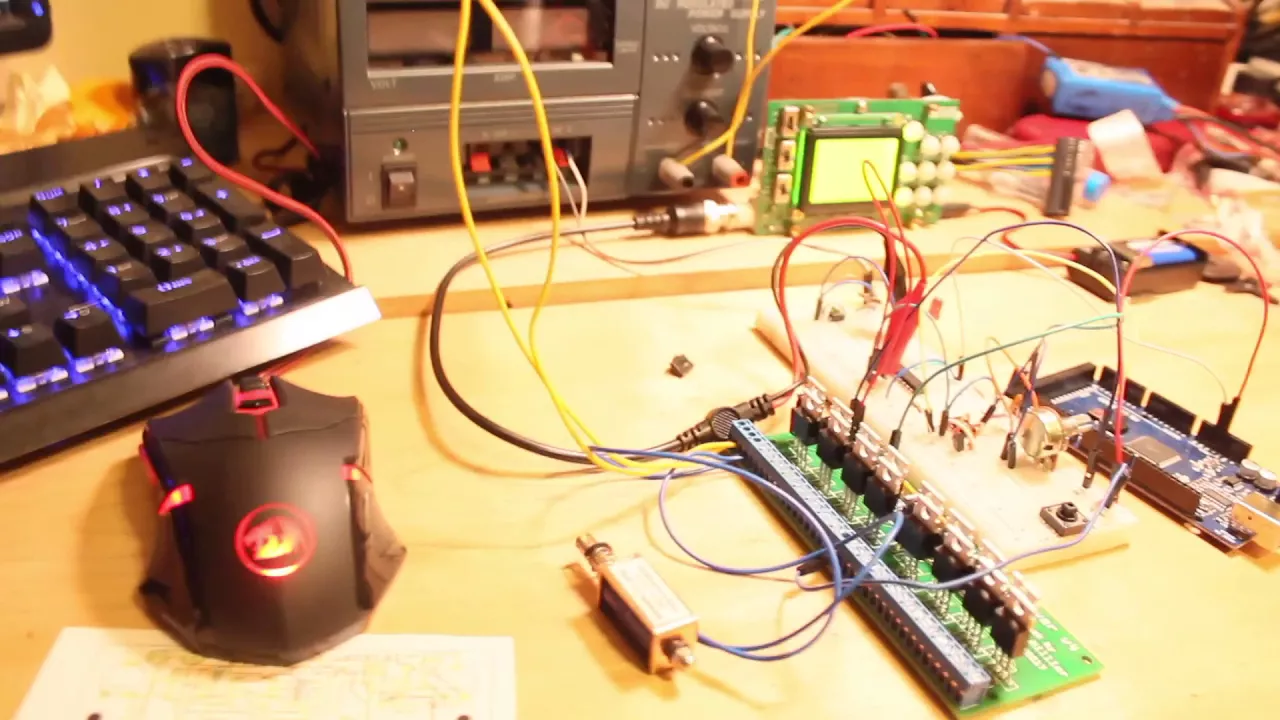
When controlling a solenoid with an Arduino, a transistor (such as IRF520) acts as a switch to isolate the high-current solenoid from the low-current Arduino pins, while a flyback diode (such as 1N4007) prevents dangerous voltage spikes (back-EMF) from returning to the Arduino and damaging it when the solenoid is de-energized.
Arduino Solenoid Control with Transistor and Diode
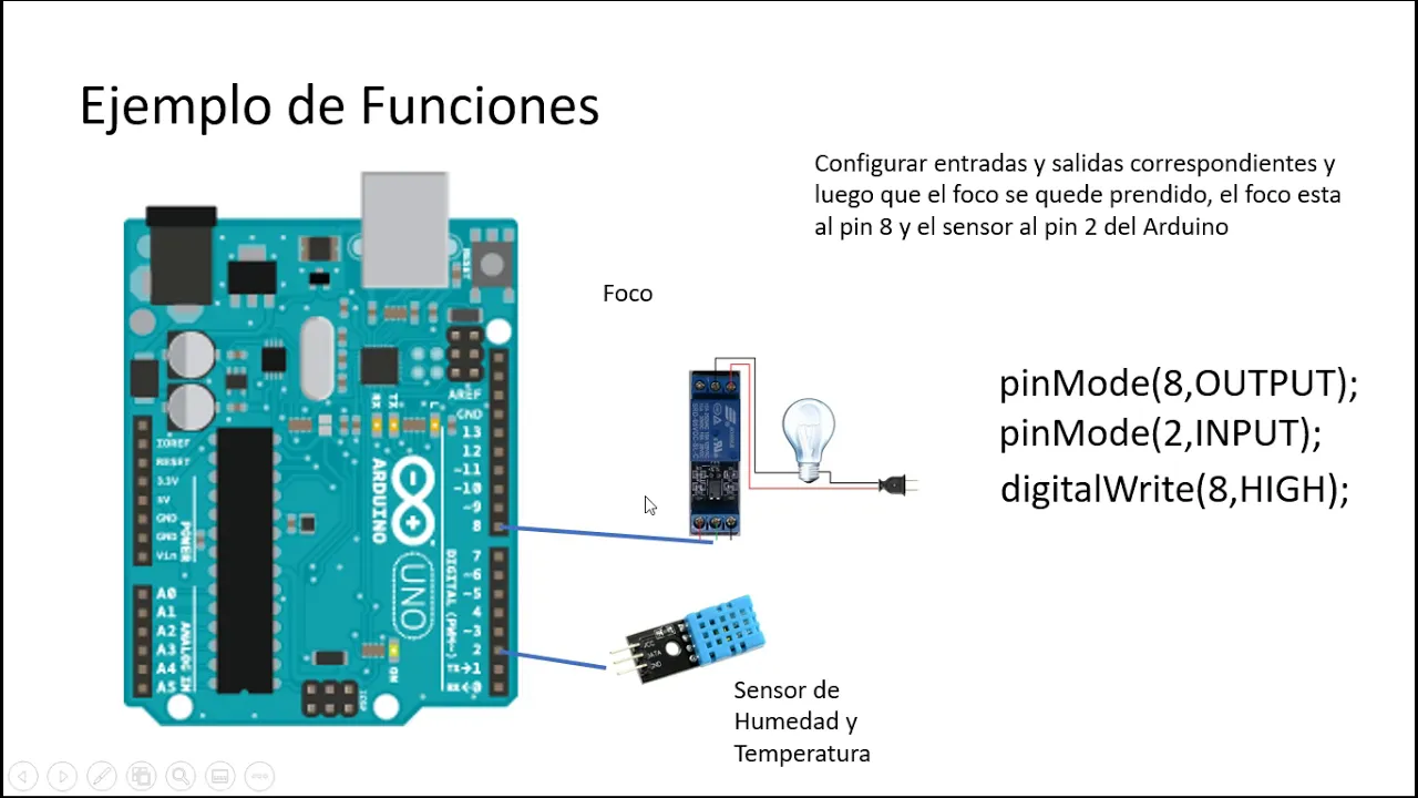
Added:Basic Arduino programming and digital I/O operations (such as setting pin modes and writing HIGH/LOW states).
Fundamental DC circuit concepts, including Ohm's Law, current, voltage, and resistor sizing.
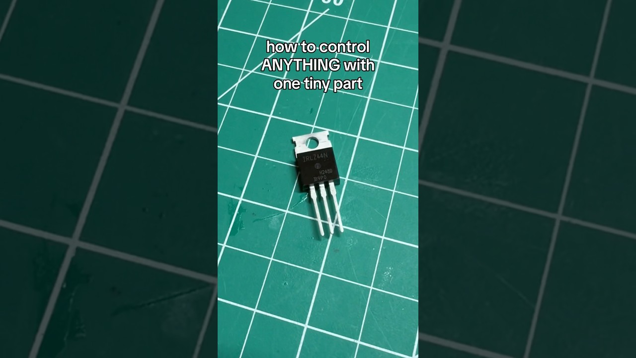
The basic operation of a transistor (BJT or MOSFET) as an electronic switch to control higher-current paths.
The concept of electromagnetism and how an inductive load, like a solenoid coil, stores energy in a magnetic field.
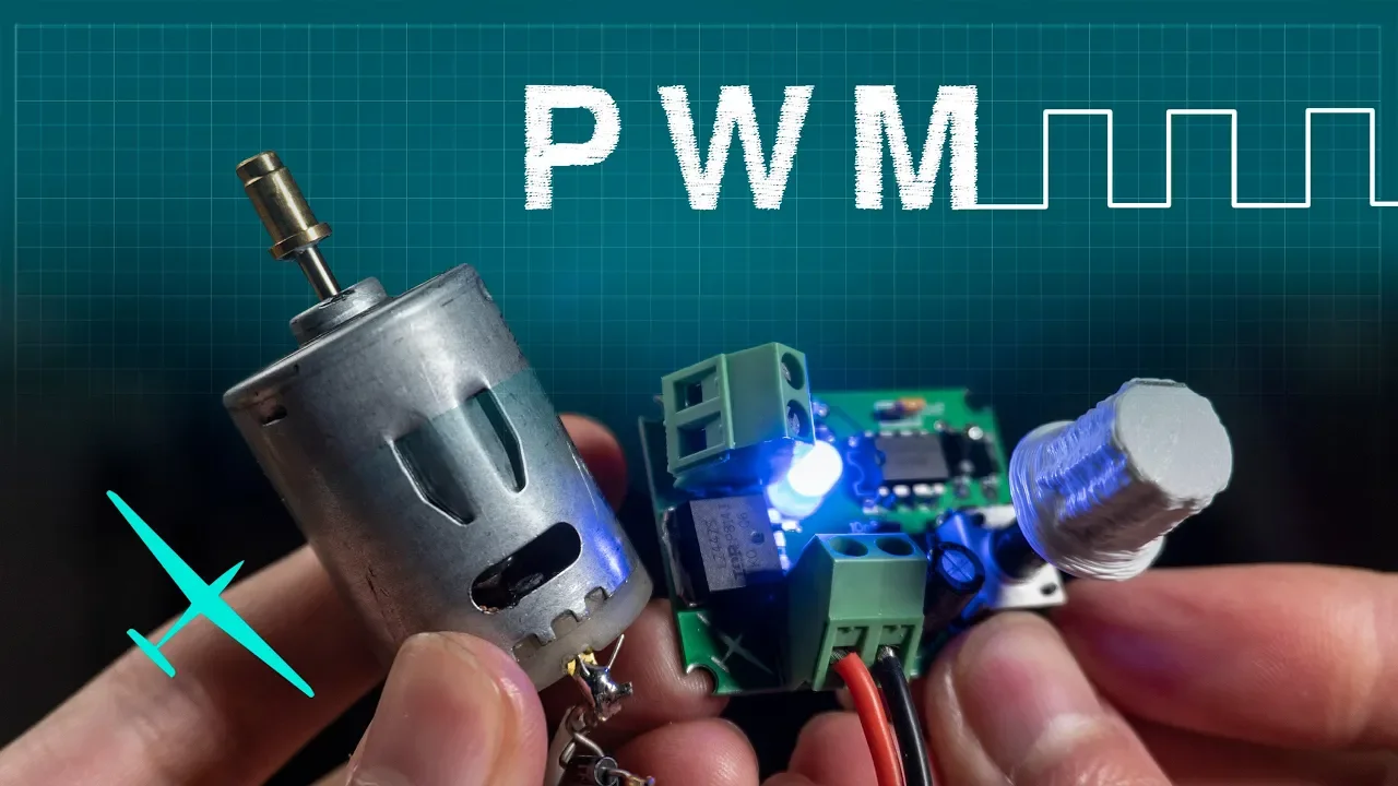
Using Pulse Width Modulation (PWM) to implement energy-saving techniques like reducing solenoid holding current to minimize heat.
Incorporating optocouplers to achieve complete electrical and galvanic isolation between the microcontroller and high-power circuitry.
Utilizing integrated multi-channel driver chips (such as the ULN2003 Darlington array) to control multiple inductive loads efficiently.
Designing H-bridge circuits to control latching solenoids or DC motors that require polarity reversal.
Applying these concepts to real-world projects such as automated liquid irrigation systems, pneumatic actuators, or electronic door strikes.
73.5K views1.3Klikes9:06Original Release: 2019-12-05
the danger of controlling a solenoid or a motor with an Arduino is that the energy sent to the solenoid can be received back and burn the Arduino to avoid this danger in this project I will demonstrate how to create a circuit with a transistor in the diode to act as a kickback so the electricity is prevented from returning to the Arduino on the pins other than the ground I'm going to create a circuit to control a solenoid with an Arduino for that we are going to need an Arduino a breadboard six cables a solenoid one transistor IRF 521 diodes one and 4007 a resistor with 300 in 30 ohms in the resistor with two point two kilo ohms so let's start creating our circuit we have this transistor i RF 520 this transistor has three connections that uses an orientation g-d sg4 gate t for drain and s for source in the gate we are connecting a digital pin of the arduino in the drain we are connecting the solenoid and in the source were connecting to the ground this is our orientation for the transistor let's start by putting the transistor on the breadboard so to connect to the gate first we are going to use the red cable for the VCC to blue for the ground in the green for the digital pin in the arduino in the gate we are connecting the digital pin we are using the green cable and connecting to the pin number 3 in the arduino but for connecting to the gate in the transistor we are going to need a resistor of two point two kilo ohms that we connect to the first pin of the transistor and then we connect the green cable that is connected to the first pin of the transistor then we are going to connect the ground the ground is connected to the third pin of the transistor and then we connect the cable to the ground of the Arduino the cable for the VCC we connect to the five volts in the Arduino and for now we connect to the breadboard to be used later for the solenoid now we are going to connect the transistor of 330 ohms in the VCC now for using the diode I'm going to make another sketch we have this diode 1n4007 this diode works this way it has a mark on this side that means on the left is the plus on the right is minus that means the current flows this way because we have the VCC entering here we are going to use the diode with a mark to the left because this diode will act as a kickback and will connect to the other side of this resistor here you have this full node and now using the rest of the cables we'll use two cables to connect the solenoid the first one will use where the VCC enters the breadboard in the other cable will connect to the connection of the diode and to the other connection of the solenoid and we are just missing one more cable to the drain will connect this cable to the center pin of the transistor and connect to the connection of the diode the circuit is complete now let's make the code and then plot it to the Arduino let's make the tilt to control the solenoid we start by creating an integer that is a variable that will call solenoid with the value of 3 this value is the digital pin number 3 of the Arduino then we create a void called set up that will define a pin mode for the solenoid as an output in the void for the loop that will make a digital right for the solenoid as an eye and then we'll make a delay for one second so now in the loop we'll do an ID for the solenoid and a delay but after that I want a low so we'll make a digital right for the sunlight as a low and wait another second now tonight we'll have a night with a second allow wait a second - detective is something wrong with an Arduino will create another integer called LED with number 13 that is the pin number 13 of the light of the Arduino so we can check the light if there is some problem with the solenoid we have to define a pin mode of the LED as an output and on the loop we'll make a digital right for the left as a knight and also a digital right for the LED as a low so now we can check when the light is on the solenoid is I and when the ladies of the solenoid should be low the LED in the sunlight is I the next second is low it will pull and release pull in release the solenoid so the code is done let's upload it to the Arduino the code is being uploaded and we can see the solenoid is working when the light is on the solenoid is pulled when the light is off the solenoid is released it will pull and release pull and release so this is the code in the circuit to control a solenoid safely with no harm to the Arduino if you liked this project each like button write a comment about this project and subscribe to this channel to see upcoming projects you
Up Next
7:31
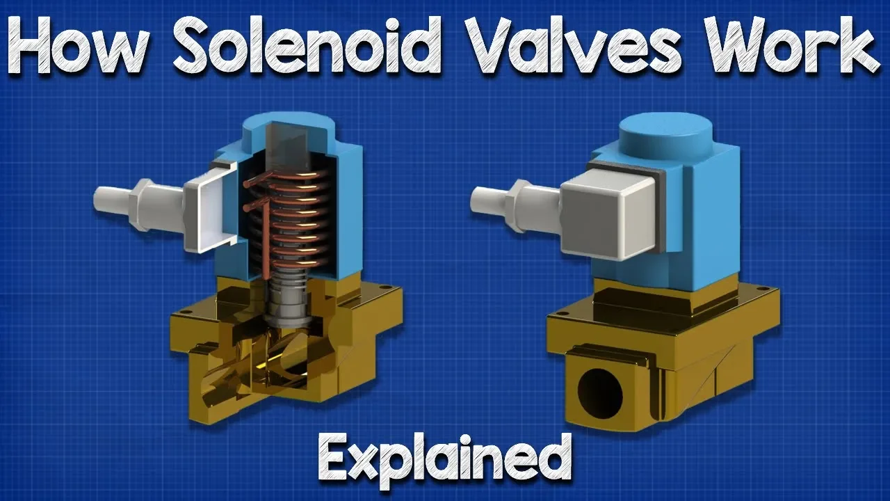
How Solenoid Valves Work: Actuator, Control Valve Working Principle
@EngineeringMindset
3.1M views•2019-03-04

30:32
Ultrasonic Transducers: Resonant Frequency Measurement and Horn Design
@imajeenyus42
229.9K views•2017-02-22

54:16
Polymer Environmental Degradation: Mechanisms & Stabilization
@iit
1.8K views•2012-07-10

33:39
How a Student's Question Saved a NYC Skyscraper from Collapse
@veritasium
22.8M views•2025-04-26
Related Study Plans & Knowledge Roadmaps
Structured learning paths in Engineering
engineering
Building Acoustic Levitators: Physics & Arduino
01The Physics of Sound and Standing Waves
02Piezoelectric Transducers and H-Bridge Drivers
03Arduino Programming: Generating 40 kHz Signals
+ 2 more learning modules
14h5 modules
Explore Roadmap
engineering
Building Peltier Cloud Chambers: Particle Tracks
01Cosmic Rays & Cloud Chamber Physics
02Thermoelectric Cooling (TEC) Fundamentals
03Custom Liquid-Cooling Loop Design
+ 2 more learning modules
18h5 modules
Explore Roadmap
engineering
Yagi-Uda Antennas: Modeling, Build & VNA Test
01Introduction to RF and Antenna Fundamentals
02Yagi-Uda Antenna Design Principles
03Antenna Modeling and Simulation in 4NEC2
+ 2 more learning modules
18h5 modules
Explore Roadmap
engineering
ECG Monitor Design: Op-Amps, Filters & Noise
01Electronics & Breadboard Basics
02Op-Amps and Instrumentation Amplifiers
03Bioelectricity and ECG Fundamentals
+ 2 more learning modules
18h5 modules
Explore Roadmap