





















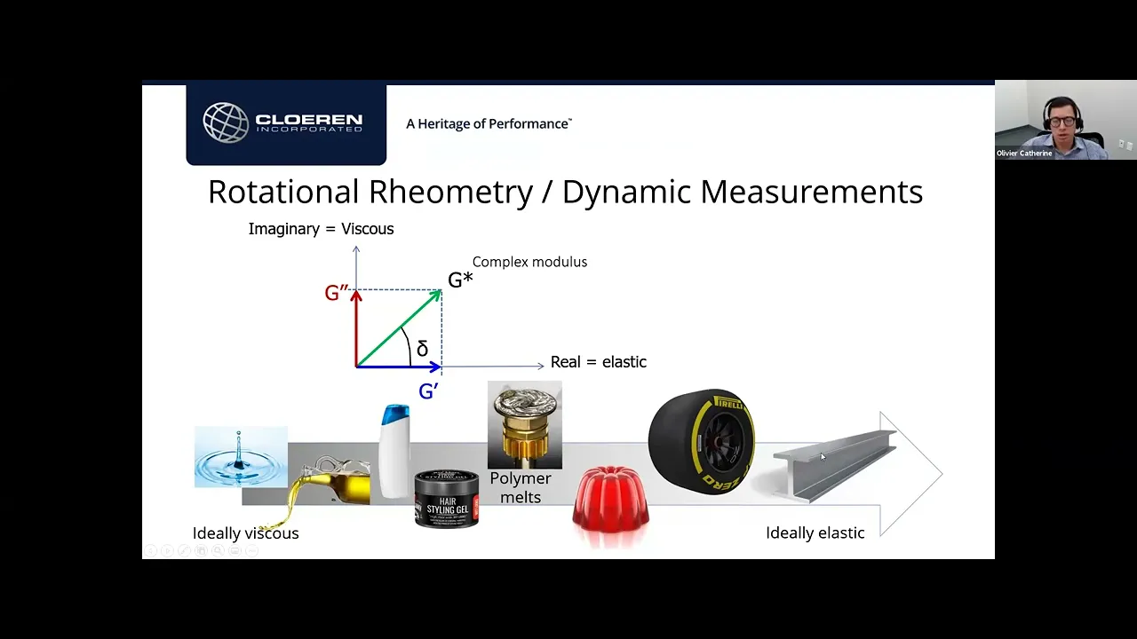


Rheology is the science of flow and deformation of matter, studying stress-deformation relationships where stress is force normalized to geometry. TA Instruments rotational rheometers measure viscosity (stress/shear rate) for fluids and modulus (stress/strain) for solids using different geometries: concentric cylinders for paints/coatings, cone-and-plate for polymer melts, and parallel plates for general testing. Key machine parameters include torque (force equivalent), angular displacement (strain), and angular velocity (shear rate), which convert to rheological parameters through geometry-specific factors. Proper sample preparation involves filling gaps completely without voids or overfilling, using appropriate geometries based on material viscosity (e.g., 8mm plates for high-viscosity adhesives, 25mm for polymer melts), and maintaining stable conditions to prevent thermal degradation or structural changes during testing.
Rheology Data Strategies: Instrument Fundamentals
Added:whether working in product formulation and development or perform in production quality control accurate reproducible data is important achieving that requires careful experimental technique appropriate experimental design and thorough evaluation of results hello my name is Kadin Muhammad applications manager at TA instruments and I am pleased to introduce you to strategies for better biology data in this three-part series we will cover instrument and Sample preparation testing guidelines and potential artifacts in your data additional resources and links to other presentations in the series can be accessed by clicking the resources widget below if you have any questions during or after the presentation feel free to ask them through the Q&A window and they will be answered by ta application scientists in the first segment of strategies for better biology data We join Dr Greg kakowski who will help us to understand instrument operation and important considerations for sample preparation and [Music] loadin welcome and thank you for joining us for the presentation on strategies for better rology data the presentation is divided into three segments and will be presented by ta rology specialist the first segment will deal with understanding the instrument and Sample preparation and loading these are the topics that will be discussed in the presentations the first as we said is understanding the instrument then we'll go to sample preparation and loading the other segments will include testing guidelines for flow oscillation in transient tests identifying Source sources of artifacts and our Advanced accessories if you've attended ta rology seminars in the past you know that we usually begin these with the definition of rology rology is the science of the flow and deformation of matter and as this slide shows there is such a wide variety of materials that are run on our rameters materials like uh automotive tires uh Foams various elastomers milk dairy products hand creams uh just a a number of things so that for us rology application scientists no two days are ever the same because rology is such a a wide and encompassing field we also say that rology is the study of stress and deformation relationships and when we use the word stress we we are referring to force uh that's normalized to take into account uh the the geometry that we have and the the materials Dimensions so we try to get these relationships between the uh the stress and deformation to get these intrinsic properties of the material that we're analyzing in this slide we say that flow is a special case of deformation because in flow your material is constantly being deformed and we try to get these relationships between stress or deformation to characterize our materials and the fundamental relations are called constit constitutive relations and the two relations that we have are actually very straightforward we have the stress which we've mentioned divided by the shear rate the shear rate is a measure of the velocity of the fluid and sheer stress over sheer rate is referred to the viscosity of the material for more solid like materials we look at the just the amount of deformation which is called The Strain and the stress over the strain is referred to as the modulus of the material we begin with an introduction to some of the the terms that we will be using to uh describe the real ogical data that we have in this slide we show what is called steady simple Shear flow and the situation that we have is we have these two parallel plates that are separated by a gap H and in between we have a fluid we put the upper plate in motion with the velocity Capital v0 the force necessary to get that velocity is f and the area of the top plate is a the bottom plate remains stationing now if we did a flow visualization study what we would see is that the velocity of any one of these particles inside the Gap sorry is related to its height y above the the bottom plate so we can propose a velocity profile with the following equation that the velocity is y over H * V 0 so if we plug in y is equal to to Z we see that the particles that are in contact with the bottom plate are moving with the velocity of zero if we plug in the particles that are at height H we see that these particles are moving with the velocity Capital v0 essentially what we're saying is that we are not getting slippage between the particles and the plates and we have this linear relationship between the veloc velocity and the height y above the bottom plate we Define this fundamental flow parameter that we call the shear rate and it's designated by the symbol gamma with a DOT over it the dot refers to a Time derivative and that's equal to the change of the Velocity in the X Direction versus the change in the y direction for this very simple system the uh the relationship uh that uh comes out is that the shear rate is equal to capital V 0 / H so this is the fundamental flow parameter in rology it's not velocity it's the sheer rate that we've described here that is a a better way of describing the motion of our fluid similarly we want to normalize the the force and to do that we in this case we just divide by the area of this plate and uh the units of of force are Newtons the area would be square meters and Newtons per square meter are referred to as pascals there are some uh operators that still prefer using dines per square cenm but the uh preferred units are the SI units which are pascals if we take the ratio of the sheer stress to the sheer rate we get the viscosity of the material going back to uh looking at at the sheer rate let's just look at this term a little bit more the velocity will be in meters per second the Gap is in meters so meters per second divided by meters will give you reciprocal seconds okay so if we take the viscosity as the stress divided by the sheer rate we could see that the units of viscosity would be Pascal seconds in the SI units in many Publications that the preference uh was still to use the CGS units which are in Poise and as we go to lower viscosity material it's often more convenient to use units like uh the centio or the Milli Pascal seconds the good thing about these is that they're all related by factors of 10 so one pascal second would be 10 Poise and one centipoise is actually 1 M Pascal second so there is an ease of conversion between uh the different units one of the things that we can do when we want to characterize our materials on our reters is to look at the viscosity as a function of Shear rate this is an example of the uh float curve that we would expect for a thermoplastic melt and UND uted thermoplastic melt and what we see is at the low Shear rates the viscosity is fairly constant and at some point we get into this uh sheer thinning region where we get what we call pseudoplastic Behavior where the material uh has a viscosity decrease as a function of the sheer rate and for a lot of industrial polymers what we will see is when we plot the visc osity and the shear rate on a log log scale we get to this region where the uh viscosity changes uh versus the shear rate uh in this straight line This linear fashion and since we're using a log log plot what we can see is that we can express the viscosity by this relationship that uh the viscosity is this Factor M times the sheer rate raised to a certain power so for that reason we call this the the power law region this is a very useful uh relationship uh in uh the processability of thermoplastic materials um one other thing is that the um the low Shear rate region is generally the most sensitive region in uh observing differences between materials as you go to the higher Shear rates a lot of times things come together together but it is in this lowest Shear rate region that we can see uh the differences between resins accentuated and what we see in this box here is that um the zero Shear rate viscosity is proportional to the weight average molecular weight raised to the 3.4 power or or thereabouts what this means is that a a 10% increase in the weight average molecular weight of this thermop PL IC melt will result in a 40% increase in the zero sheer viscosity of the material so again this is a very sensitive way of looking for differences in materials um that can be an on uh from other analyses that may appear pretty much the same so uh instruments such as our rameters are very useful for Discerning differences in these low regions that that uh result in differences in processability uh that some customers might experience changing over to more solidlike materials we have the same kind of sheer deoration that uh We've described with with flow now we're looking at a solid material and we are doing uh typically what we'll do is an instantaneous deformation of the material so in this case instead of looking at the strain rate or the sheer rate we're looking at the strain and we have this same kind of relationship that that the strain for this system is this deformation divided by the Gap in this case we used y0 as the the Gap and uh again we use our stress uh which we've described before we take the ratio of the stress to The Strain and that gives us the modulus of the material material and when we're working with sheer deoration we use the letter G to denote the uh the modulus of the material similarly um most of the time uh when we use uh sheer stress we will use the the the symbol Sigma although there are Publications where where you will see the letter uh Pi or not the you will see the letter Pi used for stress or to TAA is actually TOA is more often use than than Pi but uh we will use uh Sigma for the sheer stress and we use gamma dot for the sheer rate and Gamma for the sheer strain and uh we use the Greek letter Ada kind of looks like an N to denote the the viscosity of the material one of the tests that you can do with our instruments is called stress relaxation which is a a test that is done uh like uh that that which is Illustrated here so with our instrument we would rotate the upper plate if we were doing parallel plate testing and we would just hold it in that position and for the material that we have here which is uh soyl what we see is that the stress will decrease as a function of time this is as I said what we call stress relaxation now I have a little element here we're going to talk about these in in a little bit this has a spring and and what we call a dash pot and sometimes we can use these these physical models to help us explain the visco elastic behavior that we see when we do the testing of materials on our reters so let's let's go into this idea of visco elasticity so when we have a solid like material or of pure solid we depict that with a spring and the key feature about the deformation of a spring is that this restoring force that we would feel when we stretch the spring is entirely dependent on the displacement it is independent of the Velocity uh at which we're pulling the the spring on the other hand if we have have a pure fluid we illustrate that with this object that we call a dash pop and it's just a a cylinder laid on its end over here and we have a a piston in there and we have this uh filled with a fluid and what we would see in the case of fluids is that the the resisting force is dependent on the velocity as and is independent of the position so it's just the opposite of what we have with a solid remember the solid that force was dependent on the deformation it was totally independent of the velocity and it's just the opposite for fluids the vast majority of materials that our customers work with are going to be somewhere in between pure solids and pure liquids and we refer to these as visco elastic materials so sometimes we will uh depict the the behavior that we are see by putting a spring in a dash pot here we're doing them in parallel in the prior example I showed a spring in the dash podt in series and a lot of times what we'll do is we'll take these um what we call Voit elements and we'll make a a a series of these to to model the visco elastic behavior that we are seeing in our rological testing so um when we have visco elastic materials that the response that we get is is very time dependent as we're going to see okay one of the examples of a a very nice uh visco elastic material is uh polymethylsiloxane which is abbreviated pdms it's the main component of silly putty and what you would see is if you took uh if you uh balled up a a little sample of uh pdms and you threw it on the on the the table here what you would see is it would bounce okay and bouncing is an indication of elasticity of the material and this is also a very small time scale that that we would see um this this bouncing but if I were to take that same wad of of silly putty and lay it on the table here given enough time you would see it flow out so now it's a much longer time and we are able to see the flow properties of the material but you can see that with this material we have components of both viscous and elastic nature okay so um with that introduction uh now we will get into the uh uh idea of understanding what the instruments actually do to give us these uh viscous elastic and visco elastic measurements on our materials ta instruments actually makes four instruments for doing rological testing in today's talk we will focus just on our rotational rameters and of the rotational rameters we have two models two distinct models that we uh that we sell we have the Aries G2 and sometimes in in our presentations we will use the term native mod mode for the Aries G2 the native mode of uh deoration is strain control you'll also see us uh hear us use the terms smt that's separate motor and transducer or dual head and we have illustrations that will show what we mean by these terms we also have the DHR rameters their native mode is stress control or the torque control okay we'll call these combined motor and transducer these are single head instruments and uh you would use a riometer for for fluids definitely but it also has the capability of doing a lot of testing on solids and solid like material which we'll discuss sometimes though it when you have a a more solidlike material it's a little bit more convenient to test it with one of our solids rameters uh example would be if you wanted to look at the visco elasticity of a film uh it's more convenient to test it in a linear fashion with our one of our dma instruments where you deform this in a tensil mode uh sometimes you can get rectangular bars which you would um also test in a um a flexural mode as well on a dma we have two kinds of uh dmas as well uh the RSA a G2 is like the the linear type of riometer which is a counterpart to the Aries we have the dma q800 which is more akin to the DHR rotational rameter so with solids rameters we test things primarily in a linear deformation with our rotational rameters we test things in a rotational type of of deformation okay so what what does the the ROM riometer do it can measure both the viscosity and the visco elasticity of materials and solids and it will give us these terms that that we've just mentioned we can look at the viscosity of a fluid as a function of sheer rate sometimes we'd like to look at something as a function of the stress for perhaps it would be something that has a a yield stress we could look at viscosity as a as a function of time uh if we have a structured material or a paintt or something like that when you first start sharing it you'll get a viscosity But as time is uh increasing you'll see a viscosity decrease with with time and that's what we refer to as thixotropy of that material we can look at visco elastic materials as a function of of temperature which is what we do with uh Dynamic mechanical analysis we can look at it at as a function of frequency and um Dynamic frequency sweeps are very good for looking at the molecular weight molecular weight distribution of polymer melts and we can do uh stress strain testing and and a number of other tests to get the the visco elasticity of of our material uh we have transient responses which are unidirectional test okay viscosity testing up here typically that's a unidirectional test Fisco elastic testing is usually done in a dynamic mode of testing transient is unidirectional where you do stress relaxation you deform and hold as well as uh applying a stress or a torque and looking at the uh the amount and the rate of deformation which is what we call a creep test in uh transient testing okay so again we give that the the definition of rology you know the study of flow and deformation study of the stress strain relationships and the key things that we will be concerned about when we do our rological testing are the torque the angular displacement and the angular velocity these are the three machine parameters that we will use to get the rological parameters that that we're after so torque uh since this is a rotational riometer this is the counterpart to force so this is simply force times distance and since it's rotational uh retry we're interested in the torque how high can we go how low can we go and still get good sensitive measurements we're also interested in angular displacement you know what's the the the lowest strain the the lowest displacement we can go and still feel confident that we're getting good data or how big of a deformation can we go and again be be confident in our data and we're also interested in the angular veloc velocity you know how how low can it go and how high can it go before going into into overs speed okay these are diagrams of the two kinds of rameters that we that we sell the uh the riometer on the left is an Aries G2 type of riometer this has what we call that separate motor and transducer design so when you do a test on an Aries riometer the deoration is actually being done on the with the bottom fixture so we we do our our flow our our oscillation or our uh let's say stress relaxation testing by imposing the the deformation when in the bottom fixture and the upper fixture remains stationary and the transducer measures the torque and we have a what we call a forc Reb balance transducer which measur measures the amount of power that's needed to keep this upper plate in this case it's a plate it can also be a bob if you're doing concentric cylinder testing could be a a cone um but this measures the torque that is being transmitted through the the uh the sample the other type of uh instrument that we have and this is design the design for the the the DHR rameters is the combined motor and transducer design also called The Single head where everything is happening up here so the way these reters work these DHR rameters is that we apply a torque through this non- contct drag cup motor and we measure the response the the deoration and the rate of deoration with an optical encoder and as you could see everything is occurring up up here with the measurement the only thing that's being done here is uh that the this is also used for for temperature control but the real action is happening in the uh that upper head so the question would be well why are there these different designs for rameters and uh one of the the the the key benefits of the Aries riometer is that this provides you with an inertia free measurement of the uh the visco elastic prop properties of your material um now that being said there there is a lot of overlap between uh what both of these reters can do um when you get to some uh very weak structures some like weak uh weakly structured materials and you you want to uh characterize the the visco elasticity at let's say a frequency of of 1 Hertz you may get into um inertia issues with a a single head riometer whereas if you did this on an Aries uh you would not have that issue there are also some strong points for the DHR rameters as well and in fact we will sell a lot more of the DHR rameters then we do the the Aries but both of these are uh very uh excellent instruments for getting the visco elasticity of our uh customers products these are are the uh actual pictures of both of these rameters so we have the Aries G2 riometer on the left and this is the the most common configuration that you see for the Aries and that is with what we call the force convection oven the FCO and uh another benefit of the the Aries instrument is that with the force convection oven you can get up to your desired temperature uh very quickly it's uh uh and another thing too is there is a lot of uh airflow or uh gas flow when you're using the uh the force convection oven the the benefit of that is that you have a pristinee environment so if you have a material uh you might grab a polymeric material right out of the reactor maybe add a little bit of stabilizer and run it on your Aries riometer with a Nitro atmosphere and you'll get good measurements you will not um see the degradation of the material uh that quickly with with that design um on the right we have a picture of our DHR riometer again combined motor and transducer or single head uh this shows the uh par this the pelti plate uh being used for temperature control there are a number of others as well there's the uh the environmental test T in ch chamber that we call the ETC that's used for a number of polymer melts uh as well as torsion rectangular testing we have upper heated plate we have um uh electrically heated plate and uh you'll see this later on we have concentric cylinder geometries as as well okay so when you uh look at the the capabilities of a riometer and are looking at how you can design your test you need to be aware of the limitations of your of your instrument and uh the things that will Define the the uh accessibility of various uh regimes in the the the data collection will be the following uh parameters the the the torque range the angular resolution the angular velocity range and um although we are working with rotational deformation primarily um it's also important to know what is the normal force range and by normal force we mean like an an axial force that at times you will experience as you're you're loading a sample and you're going to encounter some resistance that you can measure by looking at the at the normal force or the the axial force and a lot of times normal force is also useful for characterizing material such as as polymer melts and another thing is what is the uh the frequency range of uh of your material now we can we can give you these um uh ranges for the different rameters uh a lot of times it will depend on the customer sample to determine uh what what range is is really necessary and um also what geometry would be the most useful to work with to get the data that that you're really interested in so on on this slide we have u a lot of information on the specs on on the Aries G2 so we we give you the specs on the uh the force transducer in in both the uh the torque so we give you the the lower torque limits for um oscillation and flow and we also give you the the maximum value that the the torqus can give you um we also have um the axial Force range so we can go up to 20 newtons of force with the with the Aries G2 here are some uh specs on the motor um uh both this column and uh the uh the column over here and we also have a a listing of the diff different temperature systems and you would select these based on what kind of sample that you are working with if you uh are working with the polymer melt the force convection oven would be the um the oven or would be that the temperature control system of choice uh but we also have some other uh temperature control systems like the uh Advanced Peltier system uh just a regular pelti plate and a sealed bath and um you would use a pelta plate also if you were doing uh like a UV curing testing on on the Aries G2 okay so with the Aries line of r we just have the Aries G2 with the DHR line of rameters we have the three rameters that that we have shown here the dhr1 the two and the three and we list the different specs for for each of these the dhr3 is our top-of-the-line uh DHR riometer and looking at the specs you can see why it it has that uh that designation the dhr2 is our mid-range uh again all three of these are are excellent uh rameters um a definite improvement over the prior generation which were the uh very useful and very successful AR rameters um these DHR reeters have uh uh are the Next Generation after the AR rameters and each one of these is a is a marked improvement over the capabilities that we had previously all every one of these has a a magnetic bearing so previously with the AR rameters it was only the arg2 that had a magnetic bearing and uh now all three of these DHR rameters have the magnetic bearing okay so when you uh decide which riometer you want and uh what testing you want to do you would ask yourself what is the the the level of performance that that you should expect um please realize that when we give specs we determine those based on the best case scenario just like if you get a car and you get the highway a mile per gallon rating that's pretty much what we are doing here as well and that these are Under the the best case scenario this is what you'd expect and this is good too because you know that below that the the data are are somewhat questionable and sometimes we've seen people will actually go sometimes half of a decade or uh or lower below the specs and they'll still get good data but we'll give you the specs that we are comfortable with in a a best case scenario so um what you need to ask yourself is what what is the level of performance that that you need on your samples so if I have a a super uh viscous asphalt sample I'm not going to test it on a 60 mm uh plate or I'm not going to use the uh concentric cylinder geometry similarly if I have uh something that's in the viscosity range of water um I'm not going to use an 8 mm diameter uh geometry and expect to get good data so um we can when we pick our instruments the instruments can be designed to test just about everything as you'll see in in one of our future slides we'll say we can test everything from water to Steel but it has to be equipped properly to get you in the right range to give you meaningful data so when you actually set up your riometer a couple things to keep in mind uh rameters little bit like people rameters need air they they need air to breathe so uh we we need to get uh a nice Clean Air Supply into the riometer and when you do the uh installation of the rameter when our our surface technician will do that uh he will also install a filter system whether it's an Aries or a DHR you'll have a filtering system that will catch some of the extra uh oil and moisture particles that that we don't want getting into the the rameters one of the things that has been a development with our um the dhrs is that the the the uh the gaps within um that be between the walls has gotten bigger so there's less of an issue of contamination uh due to any particulates that might work their way through we we we hope that never happens that you know you get some particles going through but uh with the current design that that is less of an issue but still we want to make sure that we get a good clean air going into the rameters when when we do our operation another thing too is is to be careful where you locate the the riometer in most labs this is not a problem but sometimes uh you can put a riometer somewhat close to a fume hood that when when you are using the fume Hood to remove uh noxious Vapors uh it it will vibrate and I've been in locations too where um the the the facility is located near a a train line and when the the freight train goes by you can feel the vibration so uh what you would need to do is to uh go to a a lower floor and and put the riometer perhaps on a marble slab because you want to isolate it from these extraneous vibrations so you you want to do things like have the good Air Supply and a good location uh to to maximize your chances of successful data uh acquisition another thing too that that we'll see is uh sometimes like for example like in an asphalt facility uh people have the the rameter very close to the door and people are going in and out all the time so that can affect your data too so you know if you could remove the riometer from an airdrift like like an open door or or something or keep it away from um of from air coming in like air conditioning or Heating and stuff like that um that'll increase your chances for for successful rical measurements okay uh if you are using a Peltier plate with uh with either of our rameters uh you will need to have a circulating fluid most of the time this is something as simple as as water and currently the uh circulating the circulator that we are are selling is a closed system which is an improvement over what we used to call the fish bul that we used before and and uh the thing is that we we need to keep the uh the circulating fluid clean we we don't want it to start building up uh you know Fung fungus and stuff like that which can clog up uh the flow in the uh the circulation of the Peltier plate and you know that when you run a uh a Peltier plate you must always have water circulating in it so check your your your levels at on a regular basis change it once a month and um and when you do that you you you will not have any problems with any uh any growth uh in there that as we said we we don't want you to clog up the U the circulation in the riometer because you can do damage to your your Peltier plate okay and uh on here we also uh advise that you keep the area clean where where you're doing the testing uh a lot of times this this is this is not a big issue but I know for me personally I've had experiences where I've worked with asphalt and I I wear my lap coat and I don't wear good clothes and then I do my testing and uh I clean it up and to me everything looks good and the next thing I know I take off my lap coat I put my arm on the counter and when I come up I see some stains of asphalt so avoid that you know you don't want to dirty your clothes if uh if you don't have to so keep that in mind okay um it's a good idea to uh keep an eye on your riometer to make sure that you are constantly getting uh good data one of the uh features that we have here at TA is What's called the the hotline and and perhaps some of you have called in to us and and you've you've mentioned that you've You' had some uh questionable data one of the things that we will most likely recommend to you is have you run a viscosity standard lately so we we want you to do calibrations and we want you to to do checks on standard materials at at regular intervals uh a lot of times we' we' we'd uh suggest monthly checks on on your M on your uh instrument um just so that you you are confident that you're you're getting the best data you can on your riometer so if you do get strange data it it could be um maybe the test isn't set up right or maybe there's something uh wrong with the the the sample labeling so these are things to keep in mind we want we want to make sure that you can uh reject the notion that there there's something not right with with the instrument so uh when when you first get your riometer the the riometer will be uh carefully calibrated at our uh uh manufacturing facility and we we recommend using uh standard oils that you can get uh you can check for a few vendors uh online uh you can get polymethyl Cy oxane from us uh which is polymethyl Cy oxan that we have characterized on the rameters that we know are are very much in Spec and we will provide you certain parameters that uh uh if you are within that range you can have confidence in the uh the measurements from your riometer you can also get oil standards if you're looking at characterizing the the pelta plate or the concentric cylinder uh here we give a uh a procedure where we we say go from zero to 88 pascals uh on uh a material like S600 um here we're talking about 60 mm 2° cone you can use a a plate as well the typical run time here would be 3 minutes but you could make it longer than that if if you want and what you would do then is you would plot the sheer stress versus the sheer rate and use our software to calculate the slope of that line and the slope of that line will be the viscosity of the material that should agree to within 3% of the value that you would see printed on on the jar and as I mentioned if you're uh going to be running something with the ETC or or the oven specifically if you're doing you're going to be doing something like a polymer melts uh you want to look at the the visal elasticity of polymer melts a material that's very good to run is pdms and if you purchase that from us we will give you the the two parameters we'll give you a crossover modulus and we will describe those things later and the crossover frequency and the acceptable range so run that uh on on a regular basis to to make sure that the riometer is performing as it should be okay with the DHR instrument you can uh do a uh you can have a torque calibration performed by a service engineer this is part of the annual preventive maintenance visit uh but you can also buy an accessory where you can check the torque on your own when you get an Aries G2 riometer uh you will automatically get a calibration kit which will include uh weights for testing the torque as well as the uh the normal force and within this kit you will get um poly dimethylsiloxane and you'll get a uh a standard fluid that you could run on your instrument to make sure that you're getting the proper data Okay so we've talked about the machine parameters uh that we have on these uh the different rameters and the goal of of we're going to do is we want to transfer the machine parameters into rological parameters we we we want to get data that are are useful to a rist so the parameters that were the machine parameters we're going to be working with are the angular displacement and we'll give that in in radians the the angular velocity is the the the uh change of the angular displacement with time and uh we'll denote that with the the Greek letter Omega and in this case we're using the letter M to denote the uh the torque so what we will do is we will find these appropriate factors to multiply the torque to get the sheer stress we will multiply the angular displacement by an appropriate factor to calculate the The Strain and and these factors are dependent on the geometry of our material is it Conan plate is it parallel plate or concentric cylinder and it'll also depend on the dimensions of our our system so if I'm working with the parallel plate is it uh 40 mm is it 60 mm am I working at a height of of 1 millimeter or a half of a millimeter those are the those are the um issues that are addressed to calculate that that factor the these factors are actually pretty straightforward to calculate as you're going to see in in the uh in the following slides so to calculate the viscosity uh we just get the stress over the shear rate and uh that's uh determined by a factor times the torque and we want to make sure that that the torque and the angular velocity are within the spec of the instrument okay if they're outside the specs then the data are question and these factors as I said will depend on the the the type of geometry as well as the dimensions to calculate the modulus of the material uh we get the stress divided by the strin and in this case it's torque once again divided by the angular displacement and the factor here this K gamma is the same as K gamma dot okay now uh but those will will differ from K Sigma which will be used to convert the torque to the sheer stress okay one of the nice things about rameters is that you can run things over an extremely wide temperature range you might need to change your geometry uh where you go from a low temperature range to the high temperature range but you can go typically from minus 150 up to 600° C so uh at least in theory you know and you know that doesn't mean if your material is going to degrade at 300° C then you're not going to go above that temperature but with a uh a dma uh those are used primarily to test things in the solid state and at times that it is actually more convenient if somebody were to give you a film and they said I really need to know the viso elasticity of this film as a function of temperature the first choice would be to use a a dma and you'd probably run it in in the tensil mode but as you get beyond the melting point of this material uh you would not be able to get a good characterization of this in in the tensil mode so you would need to go to a riometer and the the best Geometry for that would probably be the parallel plate and you would do this Dynamic sheer testing on your sample um you can also do a sheer testing and find out where your material is going to solidify you can go to the low temperature region the one thing to keep an eye on if if you're going to low temperatures if your sample gets gets very stiff you you can start getting into compliance issues so that's just something to to keep in mind but uh the reters give you a very wide range of of temperatures over which you can characterize your materials this slide shows what are the common geometries that are used for characterizing material they they all have great usefulness so that that's why we we sell different uh different versions of these and uh as we like to say uh with a single riometer you can go from everything from from water to steel and that's uh assuming that you have the right geometries so uh on the left here we have a concentric cylinder geometry and uh this is used primarily to test Coatings paints and and materials like that um the nice feature about the um the concentric cylinder is that there's a lot of area that's exposed to to the deformation so if you start to get a little bit of settling in the particles uh it's not that bad it's not going to have that much of an effect and if we have some excess material above this this Bob um evaporation is not as bad of an issue as as it could be if you have a cone in plate or a parallel plate with the Conan plate and and we'll get into each each one of these uh designs individually but uh the Conan plate has some uh benefits what you can see is if you go through the U the engineering mechanics of of this design you see that the the sheer rate and the sheer stress are constant everywhere in this Gap and um another very common geometry is the parallel plate geometry um one of the nice things about this is that you have some flexibility in terms of the height that you want to run your sample at and if you have a material that that is essentially solid and and it can uh sustain its own weight uh you can test things in this torsional geometry so uh if you want want if you had a a rectangular plastic piece you can you can do a dma type of test where you look at the visco elastic properties as a function of temperature okay so let's let's go over these uh one by one with the concentric cylinder uh which has been used for a a a long long time to to characterize uh uh materials uh in paints and en Coatings as well as things like suspensions and and slurries um one of the the the the disadvantages is that it compared with some of these other geometries like the Conan plate or the parallel plate uh this requires uh more volume than than the others and sometimes cleanup could be a little bit more complicated and a little bit more of a mess than it is with with the other uh geometries so here we've shown the The Strain constant for um the concentric cylinder geomet omry uh as well as the uh the stress constant and if you are new to the field of rology it would be a good practice for you to to look at the the the raw data like it would be good to look at the uh the angular velocity data and go through the calculations using the constants that we've given here to make sure that you are getting the sheer rate uh in in our software that that you are calculating manually um and do that for the stress as well look at at your torque multiply it by this stress constant and verify that that is the stress that's being given to you in the the the data table from our software you know and in many uh many of our customers who are uh heavily regulated by the FDA they they need to show that the trios is or trios is our software but the software package is validated so that you know you you know that you know that your instrument is calibrated and you're getting the right torque values and you're getting good angular velocity numbers you can convert that to the rical parameters and you're getting the numbers from the software that you've calculated manually based on the dimensions of of your geometry so here are the the concentric cylinder uh uh factors for converting the converting the machine parameters to rical parameters and uh these are the pluses and and the minuses for uh the concentric cylinder and again these are used uh very often for things like uh paints and Coatings and there's a lot of uh history to to working with these uh these show that the different kinds of rotors as well as cups and these are the the the systems that we have for the the DHR rameters I would say the most common Bob that is used is what we call the din rotor and that's the uh the Bob that I'm I'm pointing to right now it's got a bit of a a cone on on the bottom this is the one that's been around for the longest time um it does require a a large volume and by that I mean probably around 20 to 23 Ms of of material we also have another design that we haven't shown here where this is actually the the bottom part is machined out and um there's a um uh so we have the another Bob that that can be used to to get the the viscosity requires a uh a less less of a volume more like about 6 and a 12 uh uh milliliters of of fluid to get a rological characterization now um one of the things that we are concerned about as we go to uh more and more filled type of materials I mean if you start with a a fluid and then like if we start adding some pigment or adding more materials we may get into a situation where we we have a structured fluid or with especially like with a lot of particles it it it might get somewhat solid we would be concerned about things like slippage so if that's the case um we start looking into other uh Bobs instead of the the the the the conical D um is the are these veined rotors and um so we have the veined rotors and uh again the uh the D the other uh Bob that I was thinking about is what called the recessed end rotor so a little bit of this is removed and doesn't really contribute to the measurement and it lets you get away with less sample volume but uh so we have a couple of these uh vein rotors and uh these are useful for slurry materials um we also have a another rotor here uh this is called the starch pasting I've heard it called the impeller or the propeller uh this is used for a particular test that is used to characterized starch and there is a standard procedure for looking at the the pasting of starch as as you heat it up and you stir it and the outer layer will break and it that's referred to as the pasting of the material and look you look at the viscosity of of the material as a function of of time and temperature and the way to keep the uh the material stirred up in this uh this mixture is to use this impeller that you could see from the design I is is well designed to get good mixing of our materials there have been some people that have used this for other materials besides starch just because it provides uh very good mixing um we also have a helical rotor that uh some people use on some structured materials to get uh the the visco elastic properties of of these materials and in some cases um our customers have used U what we call a double Gap rotor where uh when when you load sample with with this rotor you put it in here and you fill up your sample there is fluid actually on both sides of of the rotor so you're getting like twice the exposed area um sometimes that might get you down to some lower Shear rates to to get uh more of a measurement but uh a lot of times you you can get a very good characterization just with the the regular um D rotor so so these are the different rotors that we have for the concentric cylinder testing now we go to the uh the con and plate geometry and for the strain constant this is simply 1 over beta um and beta is the the cone angle these are typically uh 2 degre one degree half of a degree but if you're going to make this calculation the calculation of the strain and the strain rate constant you need to convert that cone angle into radians and in fact uh a lot of the times with with the Aries um cone geometries they'll give you the um the angle in radians although most people are more more used to looking at the angle in degrees but if you're going to make that uh that calculation of the strain constant you would use beta in degrees and another thing to note uh is that this is dependent only on beta uh only on the uh the angle there is no dependence on on the distance from the center so in one of the earlier slides I had mentioned that a nice feature about the Conan plate geometry is that the shear rate and the sheer stress are constant throughout this Gap okay so sometimes this is useful for looking at non neonian materials uh sometimes this is a a very useful geometry if you're doing polymer melts okay and here is our our stress constant that would enable you to convert the uh the torque to the sheer stress for for this geometry okay we make a a number of um of geometries of of different uh diameters and different angles depending on the the type of material that that that you want to work with and um if we were to take a worldwide survey of people especially with our DHR rameters and they say I use the cone geometry for my testing the most common would be the 40 mm 2° okay um now when people run uh materials that are somewhat lower in viscosity uh they'll go to the 60 mm and I've seen a lot of 60 mm 2 degrees as well as 60 mm 1 Dee okay and uh this was the the 60 millim um 2 Dee was what we had mentioned for checking a viscosity standard like s UH 60 or rs600 um to make sure that you're getting good real ogical data um usually it it's not a big issue which geometry to put pick there is a lot of of overlap between the uh the different geometry so it's not like this is right and and these are all wrong A lot of times it's this is right and this is right too so it's not like a a yes or no it's yeah this and this would would be acceptable geometries for characterizing a certain material one of the things about using a cone and plate re um cone and plate geometry is that uh you need to run it at a particular Gap when you purchase a cone geometry what you would notice is that you're going to get three numbers one is the diameter of the cone the other will be the cone angle the third thing will be the truncation and the truncation Gap is the Gap at which you would need to run your experiment to get the best data okay so we show here that the the typical measurements the typical truncation gaps for the different angles are are these values 20 to 30 microns if it's 1 degree about 60 microns if if it's 2 degrees and 120 microns if it's four one of the um Concepts that we have in the world of rology is what we call the 10: one rule which says that we want our Gap to be at least 10 times the size of our largest particle so if if we're running with a u a cone geometry and let's say we're using a 2 Dee uh that means that our truncation Gap is going to be around 60 that means that the highest diameter particle that we could work with will be about 6 microns about one sixth of that um and sometimes that could be very restrictive to the the materials that our our customer has another issue with with going to a very small Gap is is when you start working with higher molecular weight materials higher viscosity materials and as you're squeezing the material down to the Target Gap you're going to generate these axial forces these normal forces and sometimes it it could take forever to get to the Target Gap that you need to be at to get the best data so for that reason for some high molecular weight materials the con plate is not a very practical uh geometry to use it's because it is restricted to that that Gap okay so again uh as is the case with with every one of these uh uh geometries there are advantages and and there are disadvantages and uh the the nice thing about the Conan plate from a a theoretical standpoint is that the sheer rate and the sheer stress are constant everywhere in in in that Gap okay um probably the main limitations are that you have to run at such a small Gap and that will preclude testing materials that have big particles or material that's somewhat high in molecular weight that generates an excessive normal force as you as you squeeze it down okay then the the next geometry that we'll talk about is the uh the parallel plate uh of all the geometries this one is the one that is probably the most used and again if if we were to take a a worldwide survey of geometries that are used on our rameters especially the DHR and the AR reters I'd say it's the 40 mm parallel plate and uh the most common Gap that people use is 1,00 microns or or one millimeter but but you're not restricted to that and and that's the nice thing about the parallel plate is you can run it at at different gaps um the the one limitation would be is you can't go so high that your material will start coming out of the Gap uh then then that would be too high but um one thing about the U the the parallel plate is that the sheer rate and the sheer stress will vary as you go from the center you know along the the axis here to the edge okay and and uh when somebody says that they've done a parallel plate uh test on a riometer and they've they've gotten viscosity versus Shear rate chances are that they are giving you the apparent viscosity and the apparent Shear rate and those values are the value at the edge okay as I said it it those values the sheer rate and the shear stress will vary from the axis from the center out to the edge but when you just give the the the basic data what somebody is referring to is the data at the edge now there are ways that you could convert the parallel plate data to Conan plate data and that's available in our software packages so if if you need to compare data and either your customer or vendor just has the uh the Conan plate and you have the parallel plate you can do testing and you should be able to get a good comparison of your data using the correction factors that are available to go from parallel plate to to con plate data okay and with the parallel plate just like what we saw with the with Conan plate is you you uh you can vary uh you can get to different flow regimes in sheer rate and sheer stress based on the on geometric considerations uh if you want to go to High sh Shear rates uh you'd use a 60 mm plate um if you want to go to higher Shear rates with that you would decrease your Gap and because at the same angular velocity you would get a higher Shear rate at the lower Gap similarly uh the stronger your material is the lower in diameter you'll go uh again 40 mm seems to characterize uh just so many things that our customers want to work with uh as you go to lower uh uh or higher viscosity materials uh you'll go to the lower diameter and for things like uh some asphalt samples people go to 8 mm diameter uh for some of these pressure sensitive adhesives they go to 8 mm diameters as well so uh this gives you a little bit more flexibility than does the uh the Conan plate and as I said this is this is used so much in uh the world of uh polymer melt rology for polymer melt rology the most common diameter is 25 mm at a gap of of 1 mm and again we go through our our table of what the advantages and the the disadvantages are for for parallel plate and as I said uh the shear rate and shear stress aren't constant but they can be corrected and as is the case with with all of our um geometries um in a lot of cases when when you go beyond a certain angular velocity a certain uh sheer rate you're going to get flow instability and that that can show itself uh in terms of uh if with you're using the Conan plate or the parallel plate the material can come out of the Gap okay um and sometimes if if it goes really fast I mean and it can it can fly out so sometimes there are realists who on their lamp coat they they'll have a little band here that was a sample that got flung out of the out of the riometer but even with u the concentric cylinder where you might think well it's confined in there after you go beyond a certain Shear rate you can start getting these uh vortices and you might see that the the shear stress will actually decrease as you go to higher Shear rates and if that's happening then you're in a a region of flow instability and you're not getting good data okay so here are some uh thoughts on on some representative materials that our customers will uh will evaluate on our rameters so uh know you you can look at things and actually get a feel for the viscosity of the material so if it's low viscosity like uh like milk and something you know even uh olive oil and and glycerin and stuff like that those flow pretty easily you can run those on a a 60 mm geometer Tre as you go a little bit higher in in viscosity 40 mm would be more appropriate uh you know if you're working um at a at a candy factory and uh you want to get the viscosity of of caramel 20 would be more appropriate and again it doesn't mean that the 40 wouldn't work it's just you'd probably feel better with this and uh again there's a lot of overlap with the different uh diameters that uh you'd be uh be working with as you go to very high viscosities uh especially somewhere around the room temperature or if you're working with a pressure sensitive adhesive at room temperature 8 mm is the uh the geometry diameter that that we would most likely be using to characterize our materials so uh when when you look at your your data uh most of the time what people are looking for is uh you know give me a geometry and give me the test conditions that will give me good data most of the time people aren't that picky that they say well I really have to know this right on the edge of the the instrument sensitivity most of the time people just say I want to get a good reliable and uh reproducible measurement of the the reological properties are material and uh with the the geometries that we have uh available in in doing the right test type you should definitely be able to to get a good real logical characterization of of just about any material that that you could be working with okay so this is an example of a of a float test that you would do this was done with a 60 mm uh one Dee cone and the purpose of this test was to verify that we're going to get uh good uh viscosity measurements on our our riometer so we're running um this was actually water with just a little bit of little bit of surfactant if you were to run water by itself you would see the effects of surface tension in the low Shear rate region the material would look like a like a non neonian Shear thinning material and then as you go to the higher Shear rates you're going to get into flow instability so by using a a surfac or what I used was silicone on on both the bottom and and the top uh geometry um we we remove the uh the surface tension as you can see we we got good measurements to um to to low Shear rates and this showed that we were able to get good measurements to about uh 80 uh nanoon met so um you know a lot of people you know when you talk about Micron newton meters it indicates that boy that's a very sensitive measurement and now we're going into less than than a tenth of a micron meter we're going into the Nano Newton uh meter range and if we had used a um a viscosity standard uh other than water we we could probably we we could extend this down to to even lower torqus and if you've seen our our presentations on the DHR and we have one for the Aries G2 as well where we will show you uh what the specs are and how far down we've gotten in torque with some of these viscosity standards you can see that it's very impressive that we can make these measurements at such low low torque values and they would be reliable so uh you know and what you would do is if you were to do a a test a lot of the times that the accessible range for your material is going to be a lot more restricted than it is for these ideal samples that that we're running so keep that in mind you know just just because you we say that we can get to these uh very low torque values for your material if you have things like a uh um water that that has surface tension or um for some materials like if you're looking at toothpaste at certain rates uh you're going to get slippage you know that the the riometer could go to the the angular velocity that you want there there's no problem there but the data itself uh will become questionable because of some other uh factors which will be discussed in uh in our subsequent presentations by other uh rology Specialists okay now here's a test that was done on a concentric cylinder geometry with uh different paints and the idea that we wanted to get across here was that it's really important to characterize material like like paints over as wide of a range as sheer rates as possible because in their usage you know whether uh when they're being made and processed and uh conveyed and and uh put into the the paint can or whatever uh to storage and then application by by a consumer and drying on the wall um the material will be exposed to a very wide range of sheer rates so in our instrumentation we we will go over uh as wide of a a sheer rate range as possible to show what kind of behavior you can expect and um sometimes what is useful to see is just by changing a formulation uh of a paint or of a coating you're going to get not not only changes in the the absolute number but you you can see how some of these things have different shapes when you uh uh when you change the formulation and then you run them on the riometer so uh exactly how that's going to correlate with field experience uh sometimes I'm not sure but this is very useful information for most uh people who are involved in this case in in the codings industry as to what kind of behavior uh they'll see and what the consumer will see when they uh when they they get their paint and when they start applying it on on the desired surface okay and um one of one of the last geometries that we'll talk about is the uh the torsion rectangular geometry so um in general this is while this is used in a rectangular geometry uh a lot of people can easily get a rectangular specimen of let's say a plastic and they will do a dma type of test and by that I mean they'll look at the visco elastic properties as a function of temperature and they'll get things like the the the glass transition temperature the melting point they'll get the modulus of the material so you'll know how much strength this uh material can contribute if it's in a a loadbearing application and and how high you can go in temperature before you start to lose that uh that strength contribution of your material uh we can also accept um uh cylindrical geometry and um some of our customers have been uh using this type of geometry with some like asphalt Aggregates they can they can core out asphalt samples and they'll they'll machine it down to a cylindrical specimen and then they'll do a dynamic testing on a uh a specimen using our um our torsion cylindrical uh geometry so that's another uh geometry that's available and again this is something that's that's somewhat solid uh if you were to try to use a film uh a thin film this might be a little bit more difficult but there are just a very wide range of materials lot of specimens that could be run in this torsion rectangular geometry okay here's an example of a test this was a temperature ramp on ABS material so you could see the characteristic behavior of the storage modulus where uh we get this drop in the storage modulus at at this point here uh which is where the the buad starts to lose its contribution and uh here the the storage modulus continues and then at around 100° the acry NIT trial uh styrene acry nitr loses its mechanical integrity and you can see these characteristic uh peaks in the uh the the loss modulus and the T Delta curves for for this material that enable us to identify the uh the the glass transition temperature of this material okay so that ends the uh section of of knowing our riometer uh remember that uh uh the the the main things that we're looking at are the torque the angular uh displacement resolution and the angular velocity and uh when we use the different geometries and we use the appropriate factors we we convert the machine parameters into the rical parameters which will give us fundamental properties of our materials okay in our next section we will address sample preparation and loading and uh now you are familiar with u the riometer itself and you know you're aware of the the limitations with with with those parameters I just mentioned but another very important part of getting good rical data is to make sure that you've prepared your sample correctly and then you've you've loaded it uh appropriately onto your your uh your rameter and and you've taken precautions to make sure that your material will be stable uh when you're you're doing your testing and uh sometimes that could be a challenge okay among the materials that are are run on our rameters are uh these materials that we call structured fluids and uh this encompasses a very wide range of materials as as we mention here you know even something like a milk is a uh a structured fluid I know we've we've run things like a baby formula on our riometer to look at the visco elastic properties of our material so it's not just flow on I mean when we see something like a a baby powder or if you get chocolate milk um more so than than regular milk but regular milk as well there is a structure to it there is a visco elasticity that you can measure with our riometer and uh on the high end you could look at things like um toothpaste which uh when when you put it on your uh your toothbrush uh you want it to have a structure so that when it's it's resting on top of the bristles it's not going to just automatically sink down into into the Gap there but it'll it'll stay up on your bristles until you're you're ready to uh to brush your teeth and and you're going to make make the toothpaste flow so there's a wide range of these and the the problem with a lot of these structured materials is is they could be very sensitive to um mechanical and environmental conditions so um you know when we work with some of these things uh a lot of them uh have structure because there are these particles inside them and um and then they will interact with each other to to give the structure but um depending on the parcle size that that may preclude the use of a cone and uh cone and plate geometry or or even a parallel plate and you may have to use uh um a vein geometry to get some good data on on some of these materials um one of the things I should mention at this point but even with the uh parallel plate geometries I think the examples that we we've discussed so far you get the idea that it's just a smooth geometry on the bottom and smooth geometry on top we do have cross-hatched variations of these so that you can get a better grip on your sample uh to avoid slippage or or at least to to delay it for a while to get to get more good data so that that's something that's useful for some people who are using um the rameter to characterize their their structured materials and um a lot of these properties can can be very time dependent and uh the way you load your sample onto the material can affect the the the final results that that you get and uh at times there's a lot of effort that goes into uh writing up your your procedure so that you are confident that you're going to get good meaningful and reproducible data so uh we have some U uh uh tips over here and there will be more tips given in some of the other segments that are part of this uh presentation and uh low viscosity fluids are are often uh uh uh the one of the easier things to to characterize uh you know especially if they viscosity standards with those you usually don't have to worry too much about evaporation but um but if you do have a uh a concern about evaporation many times you can use um the variations of our solvent trap to to minimize the amount of evaporation and give you enough time to get good uh good measurements if you have um a material that that has some uh particles in it or maybe uh it's just not it's not perfectly homo homogeneous you know you you obviously want to stir the material to make it as homogeneous as as possible um you know sometimes when you open up a can of something and you can see some separation there uh you know that it needs to be homogenized before you you you can believe that you're going to get good reproducible data okay we'll talk about some uh loading techniques with uh with the uh uh low viscosity fluids as well one thing that we uh we mention here is you don't want to uh put any material back in the in the container just to to avoid any kind of contamination sometimes things like paste and and slurries can offer some uh unique challenges to to getting a a good uh rological characterization so if you have something like uh like dough um you might want to think about using that the parallel plate maybe with the cross-hatch geomet cross-hatch geometries top and bottom uh you may want to go to a little bit higher Gap because of some of the the particles and to avoid evaporation a lot of times we'll put on a layer of mineral oil that that won't affect the the the Risco elastic measurements but it it will inhibit the U the evaporation so um and um if you don't use that sometimes you can see a crust developing on the side and and you'll start seeing that the the modulus especially the storage modulus going up with time uh because of the crust being formed around the the edge of your of your dough sample or something like that and um so uh things like slurries you know if they if they settle then they form a cake uh you know you don't want those to to form a real solid cake and um and potentially ruin your your rotor and and cup and uh gels uh can also be uh very sensitive sometimes if if you uh you know if you if you load them in a in a somewhat aggressive manner you can destroy some of the structure that either will will not come back it is irreversible or it'll take just a very long time for that the structure to come back uh to its full fully developed State and often that is where you want to make this measurement is when the material is in its fully developed state that relates to things like the uh the St the stability of the material it relates to how hard the material will be to to start flowing so um we would like to get that fundamental characteristic of the material in it it's fully developed structure uh as as a characteristic of that material so and that could be a little bit challenging so um we go back to how you would handle and load a a low viscosity fluid and in this case what we're doing is we we put a u a certain volume and um one of the features in our realy software packages is that if you enter the correct geometry and the dimensions and all that the softare will give you the the absolute minimum amount of material that that you're going to need to perform this test now for a very low viscosity fluid like like what we have here in in the slide um you might put down even just a little bit less than what is called for uh from the software and uh what we suggest that you do here is uh rotate the um the upper head in this case it's a DHR with a angular velocity of one radian per second so you can go into the software and set one radian per second and while you're loading the the fluid and uh you can put the upper head in rotation with a gap of with a speed of one radian per second and it's actually better to use Radiance per second than Shear rate because when you get a certain Shear rate uh when you lower it it actually is going to increase uh so you if you lower it it's going to start accelerating and really you just want it to go at at a certain rate and then what we what we find is that when when you go down to the test Gap if there's a little bit of of a void uh you need to fill that up to get good measurements and the way you do that is you can you can use a um a pipet and and just add you know a few drops at a time until the Gap is completely full and and and it's very interesting looking at the um the the screen uh on the riometer head of something like the DHR when you're doing this you can see what effect it has like with each drop that you have you'll see a noticeable increase in the viscosity of your material and hopefully when it looks good you know just you using your your visual judgment you you will you will be right around the the viscosity that that's listed on the um on the bottle that uh that you got this this standard from so uh when you're done with that uh you can stop you can click stop the motor and then you're you're ready to uh to start your test and uh when we load the uh paste and slurries you know depending on what their constituency is uh you can uh just uh uh take out um sample with a a spatula and uh you know if it's a less viscous material as we suggest here you can use a syringe if if you cut off the the tip sometimes that's a very convenient way of of getting sample and then loading it onto uh onto the the Peltier plate in in this case and and in this situation we actually suggest getting like about a 10 to 20% exit and then we are going to go to the trim Gap and um once we get to the trim Gap we're going to lock the bearing we're going to trim the excess material and then we're going to go to our our final Gap now because of the the sensitivity of some structures that that we could be working with with paste and slurries um we suggest that you that you use the exponential Gap closure to go to the the the last few uh microns in the um in The Descent of the head that's been found to to be more gentle and that has less of a chance of of disturbing your structure so um we want to show you what what things should look like when you have a a good loading um obviously you don't want to have any kind of a void uh between um the the the plates here you know you don't want to have any sample where it looks as if sample really does belong there so here you can see that there's this void with this we would be getting an erroneously low value and sometimes if you run something that has some volatility um what you'll see is that uh you might start out with a good measurement of the viscosity As Time increases and maybe there's some evaporation it's going to to look like this and your viscosity number numbers will start coming in lower than they should okay so here is an overfilled sample you you can actually you know if if you overfill it you'll see the viscosity coming in higher than than it should and and some things vary with how sensitive they are to this uh uh overfilling and then here it's uh you know it's uh just right so uh um you know here it there's a little bit of a bulge to the sample that's okay okay and uh we should get good measurements when when we have this filled in in this fashion okay so uh we mentioned that we we would like to give a consideration to uh closing uh the to the way that we close the gap and we would like to do this in some cases as gently as possible so if we go into the options and we go into the the Gap you'll see that there are some uh different ways that we can control the way the head goes down to uh go to the Target Gap so we have linear exponential you could use force uh to uh to to do that so uh in this case what we're using is a strictly linear uh way of closing the the Gap so here we go to some uh perhaps this is going to take us to the trim Gap and then we're going to use a a certain linear rate to to get to the desired uh test Gap okay so it it goes down in in this fashion however if we had chosen a uh an exponential closure notice that there's a little bit of a there's a little difference here in how the the uh the head will go down and this is a bit on the the gentler side of uh closing the uh the Gap this can also take a little bit longer longer so uh you know if if your material is not this sensitive you can use a convenient linear um uh pattern for closing the Gap if you are concerned about the sensitivity you do have that option of using an exponential Gap closing okay so this is an example where uh we close things very quickly on a linear uh with a linear uh scheme uh here we've used an exponential and as as we had mentioned the concern that we have with this rapid linear uh closure is that we may be destroying structure that we really would like to get in our measurement and sure enough we see that there has been some destruction here of the structure it it's building up but after a thousand seconds it's it's still just kind of approaching what we had at the beginning with our exponential closure okay our exponential closure so if you if you uh have a material that's sensitive you have this option of closing things exponentially to avoid this um this damage of your of your structure okay um this is a uh um an interesting geometry not used all that that often where uh you do have have the option of uh using a container and and the classic example of this would be a a paint container where you can you can get your your paint just coming off the line and you can put it on this this lower uh cup holder and this would be a top a pelty although you would really just do this temperature at room temperature you can put it in and lower your Your Den rotor or your recessed end rotor and you can get the the viscosity of the material and and see if you're you're getting um the viscosity versus Shear rate that that you expect to get for your product so uh uh this is another option that people have if you don't even want to worry about transfering like you you can get a can and just bring it there maybe you want to stir it um but you can test it as is uh at top the the pelti plate another uh great usage of using our rameters is looking for polymer melts is looking for the rological properties of of polymer melts and we can get these in in different forms uh the the forms that we show here are pellets and a lot of the times the uh the manufacturer of the plastic like the uh of the polypropylene the polyethylene what they will do is they they'll get this fluffy material out of their reactor they will add a certain amount of stabilizer and they'll run the material through an extruder and the end result will be pellets and they will sell these to the injection molders the blow molders in that so uh a lot of the times when when people uh are looking to evaluate polymeric materials it's going to be in the form of a melt uh sometimes you can get the fluff like out of a reactor um or some times there are some other cases where you're you're getting a a polymeric material and it is kind of in a flaky or a powdery form that uh you know we'd like to uh get the measurements of the rological properties of and uh you know here we also show the example of U of flaky material as as well so um most of the time what what people would like to do if they have the uh instrument mentation to do this is to make a plaque of your your polymer melt or the powder or the flakes and uh you press it at a high temperature we say 10 to 20° above the uh the test temperature you apply pressure and you want to give the material enough time to flow and then you you do this slow Cooling and once you take out your plaque um you can buy this uh this punch from us but we have this kit this melt kit which will enable you to punch out 25 mm discs or 8 mm discs for running on on our rameters so uh for most polymer melt rology 25 mm seems to be uh uh the the the best as I said if you're running um some lower temperatures if you're running asphalt or adhesives uh a mm is uh is the material is the diameter of of choice so uh here again we talk about U molding in this case uh molding uh molding with uh powders and and Flakes and um one of the things to to keep in mind is you need to know whether your material needs uh stabilizer like uh you know an antioxidant uh you know one of one of these various uh material so that uh when you want to run your your melt your in in the riometer it's not going to thermally degrade it it's got the stabilizer to maintain its properties and uh you you can see changes if you don't have stabilized material uh primarily in the G Prime parameter and and I've seen things change in both directions versus time sometimes you can see chain cision where the material will will go down in MO molecular weight versus time sometimes you can get cross-linking and what that would lead to is is an increase in in the G Prime uh as a function of time so both of those sit situations are are to be avoided you would like to see at least during the time that you're testing the material that your G Prime and gouble Prime are are nice and flat that means that it's it's nice and stable so uh sometimes you will need to add a a stabilizer your s to make sure that the material will be stable as a a function of time for the duration of of your experiment okay so um one of the things when you know we had mentioned uh pellets we'll talk about that uh a little bit more but one of the things about the pellets is that if you do get it from the the the the manufacturer generally those are going to be well stabilized and you'll be able to run them on our riometer uh in a nitrogen atmosphere you will still run it in a uh a nice pure nitrogen atmosphere but it's not as as sensitive as some of these powders and the flakes could be if if you don't add uh stabilizer to them so um when we have uh uh semisolid samples as we are referring to here uh a lot of times the the thing that you will do is you know you'll cut out a uh a sheet and um uh press it down you if if it has the right thickness you can put it inside this uh this uh punch press and punch out a specimen of the appropriate diameter okay um one of the things that uh we need to be aware of uh over and above the the regular stabilization for some materials uh like your your your nylons you know the polyamines or polyest ERS polycarbonate um ABS a number of things uh also need to be um dried be because they are sensitive to moisture so if I got pellets of of a nylon material and I were to run it on the riometer I would see that the the reological properties changing with with with time even though they're pellets uh just because they they need to be dried out in order to get good real logical parameters and uh sometimes it's good just to do this uh experiment where you you take pellets as is and then uh do a Time sweep or take uh the pellets and dry them typically like for about 4 to 6 hours at 100° C um but you would have to verify whether that is appropriate for for your material and do a Time sweep and hopefully what you would see is that your G Prime and your gouble Prime that your material is stable as a function of time so um so here we talk about dry uh some of these materials that are moisture sensitive okay so loading a uh a disc is is somewhat uh easy uh one thing I would add is uh it it's a good idea to wear uh gloves while you're doing this testing uh because you are working at high temperatures your Plate's going to be 150 190 230 maybe 300 so that's a that it's a very hot temperature so you don't you don't want to hurt yourself so if you wear gloves um and let's say you're working with the molded disc as as you are here uh you you you punch out the disc and you might want to get a pair of tweezers to to load it onto the plate uh sometimes if you're wearing gloves you can just pick it up and put it on the plate and it's it's not it's not all that uh um dangerous you know it it it it works pretty well then what you'll do is you you'll lower your head and um one of the things you'll keep an eye on as as we mention in this uh box over here is that you will monitor that the normal force uh as you're getting to your trim Gap okay and uh you you can do this a couple ways you know you you you can set your Gap to go to to to the trim Gap and you you you'll max out on on the normal force usually it'll it'll react by just holding it at that normal force and keep going down some people feel a little bit more comfortable by saying let's control the normal force they'll say I want to impose maybe 20 newtons or 30 Newtons and then you could say stop when you get to a certain point and that point will typically be the trim Gap and as we had mentioned in a previous slide if you're running running at 1,000 microns which is the most common gap for a thermoplastic melt uh your trim Gap is going to be 1,50 some Some people prefer to go to 1,00 for your trim Gap that's a little bit more but um you want to go to a trim Gap and then use the uh appropriate trimming tool to trim the excess material uh from um from your sample you know you so so you do the trimming and then um you close your your oven and then you go down to your to your test Gap okay now with with pellets with both the the DHR riometer and the Aries we we have versions of uh melt rings and uh the example that we've shown in this slide is uh the setup that we have for our DHR riometer and uh with the DHR Romer you get this little aluminum strip and when you when you uh fold it on itself there will be like a little hook that'll uh maintain it as a ring and this ring will rest a top a stage you have a the 25 mm diameter plate on the bottom but it goes out to 40 mm on the edge so there's a little space that can be used to put your uh your melt ring and it makes a little well for your polymer pellet so you can load that up then you go down to your um to the desired Gap and uh when you go down you can remove the G uh that ring uh it's usually a good idea to hit um uh bearing lock when you do that so uh just in case your your your upper geometry wouldn't start rotating and you move that and then you go down to your trim Gap you trim the sample then you go down to your your taret tar Gap and You Begin your test okay so with uh with pree many times you have to put multiple layers uh a top each other and um so you uh you will stack three or five three to five layers of these prepregs or the adhesives uh put them in the oven to the uh to the temperature that you want and um then you may need to use normal force to get to your your desire Gap and then uh you know depending on the specimen you have you may need to do some some trimming or or or not but that's how we would work with the prepregs so with um with normal force uh a lot of the times you want to keep an eye on this to to avoid going to the upper limits of of what the riometer is uh is made for so when you when you go down to a a a given Gap and then you do your trimming what what you would like is for the the normal force to be as as close to zero as possible because there's the concern that that you would get these extraneous Effects by by squishing down on the sample so that's the ideal is to uh get that measurement without the imposition of uh an extraneous normal force sometimes you can't do that uh depending on what material you're working with so the the best thing is to report the the data uh and and if you do have a normal force uh then then that's fine then just make sure that that's reported that that has been applied to your sample and sometimes we actually do want to apply a normal force on certain adhesives just to make sure that we're really getting a good contact between the plates and and our adhesive you know you don't want to if you have a like a tape or something you don't want to have any kind of a um a gap and sometimes the best way to do this is to impose this axial this normal force to make sure that you have uh good contact but a lot of times when when we do this uh Gap closing um we don't want to exceed the limits of our uh of our instrument and as we mention in this uh statement here uh this may take forever if you're using the cone and plate geometry so if you use the cone and plate geometry uh sometimes it's it's good to uh change to the parallel plate geometry this definitely gives you more freedom and it's it's a lot easier to load your sample uh into the riometer so um anyhow uh control of normal force is is something that you have at your disposal to do the appropriate loading of of your sample so in this case we actually showed that by by doing a uh a faster uh uh closing where we did 100 microns per second and then we let the material relax at a certain Gap it actually turned out to be better than when we used uh 50 microns with 50 we developed a certain uh normal force but you can see it it's uh these are still you know taking a while to uh to relax so um you know depending on what your materials like that you could find better uh rates to use you know you try to get that done as as as quickly as as possible but without having any long-term effects on your your measurements okay so um when you uh when you go to your Gap typically what you'll do is uh you'll go to a a trim Gap that's 5% higher than than your target Gap and then ultimately you'll go to your final Gap and uh and again we we we keep an eye on the uh the speeds for uh for closing just so to to avoid any extraneous effects on the measurement on on our sample okay that uh that concludes the uh the second part of uh of this presentation and hopefully this has had some uh information that is useful for you in uh picking the equipment that's appropriate for your material and in uh designing the tests that you would uh that you would use in uh in your evaluations there are uh other opportunities for gaining more uh knowledge of uh real ogical testing uh from ta and uh I'd like to list a few of these for you uh number one you can look up all this information on our uh ta website which is TA instruments.com and um if you go to training you could see some of the the things that are available such as Theory and applications uh on-site training quick start ta Tech tips as well as our applications Library you can go to our applications Library type A a keyword and you'll get a number of of very good articles that will deal with the the topic that that you're interested in so with the theory and applications courses those those are held six to eight times uh primarily in Newcastle Delaware sometimes they are done at at at other locations but the main location will be here in Newcastle Delaware and they'll cover the the theory of the measurement some of what we've discussed in this presentation as well the instrum instrumentation design calibrations troubleshooting data analysis and applications and uh sometimes when it's it's difficult for uh people to come to the uh the Newcastle facility and uh perhaps they want a number of people to be trained on their real ogical instrument the best option is to do um on-site training and another benefit of on-site training in addition to working on your instrument and you're working with your material you can also have a number of people that are uh uh attending that and and are getting rical training and typically although we will cover all the all the fundamentals in that we will do our best to to tailor that on-site training class to your particular application so uh in some cases the on-site training is is the m most effective way of having many people trained on their instrument we have some uh quick start courses that are on the website those are about 60 to 90 minutes long uh you can get them any day any hour of the day and those are free of charge so so look those up with uh ta Tech tips uh you could go to uh YouTube and you can see some of these short two to four minute videos that will uh give you further advice on uh ways to do uh good testing on on your riometer and one nice thing about these is that we update these uh about every week so uh uh every week you try to make it a habit to check for some new uh Tech tips in in YouTube and uh hopefully soon you you'll find one that's appropriate for uh for your application okay so uh that concludes our uh first segment which was understanding urometer and Sample preparation and loading um this is record reced and uh it will be archived and available on our uh ta website we ask you to stay tuned for the next segment which is testing guidelines and that will include flow oscillation and transient uh applications and we thank you sincerely for your interest in rology that concludes our first segment instrument fundamentals in Sample preparation a recorded version of this segment and entire series is available through the TA instruments website be sure to join us for the second segment in the rology series where we will take a look at testin guidelines [Music]
Up Next

App Preview Videos for iOS: Optimize App Store Listings
@Appradar
10K views•2021-03-02

Triumph of Orthodoxy Icon: Byzantine Art & History Explained
@BenCallan
2.1K views•2024-08-06

FastAPI vs Flask vs Django: Choosing the Right Python Web Framework
@TechWithTim
302.5K views•2024-05-26

Game of Thrones Opening Credits: A Cinematic Analysis
@gameofthrones
46.3M views•2011-04-18
Related Study Plans & Knowledge Roadmaps
Structured learning paths in General & Interdisciplinary Studies