In the Michelson-Morley experiment, even when the total path lengths are equal (resulting in zero phase difference), fringes form because the telescope observes a beam rather than a single ray; different points on the screen receive light from different portions of the beam that have traveled slightly different geometric paths, creating varying phase relationships that produce alternating bright and dark fringes at positions where path differences are integer multiples of wavelength (bright) or odd multiples of half-wavelength (dark).
Why Fringes Form in Michelson-Morley Experiment | Phase Difference
Added:Deep Dive
Basic principles of wave optics, including wave interference, phase difference, and path length difference.

35.Chapter - 10 | Wave Optics | Path Difference & Phase Difference | Physics Baba 2.O
45.7K
This comprehensive lesson covers the core principles of wave interference in optics. The key concepts include: (1) The relationship between phase difference and path difference, where converting between them involves replacing π with λ (wavelength); (2) Constructive interference occurs when phase difference is an even multiple of π (2nπ), with path difference as integer multiple of λ; (3) Destructive interference occurs when phase difference is an odd multiple of π ((2n+1)π), with path difference as odd multiple of λ/2; (4) Intensity is proportional to the square of amplitude (I ∝ A²); (5) Maximum intensity in constructive interference is I_max = (A₁ + A₂)²; (6) Minimum intensity in destructive interference is I_min = (A₁ - A₂)². These principles form the foundation for understanding interference patterns and solving wave optics problems.
Click to watch →

WAVE OPTICS : Most Expected Questions in 1 Shot | NEET
27.7K
This comprehensive section covers the core principles of wave interference. The relationship between phase difference (Δφ) and path difference (Δx) is given by Δφ = (2π/λ) × Δx, where λ is the wavelength. For constructive interference (bright fringes), the path difference must be an integer multiple of the wavelength: Δx = nλ, where n = 0, 1, 2... For destructive interference (dark fringes), the path difference must be an odd multiple of half the wavelength: Δx = (2n-1)λ/2, where n = 1, 2, 3... When experiments are conducted in media other than vacuum, the wavelength changes to λ' = λ/μ, where μ is the refractive index. The intensity at any point is given by I = I_max × cos²(Δφ/2), where I_max is the maximum intensity and Δφ is the phase difference. The path difference can be calculated geometrically using Δx = (d × D) / D, where d is the slit separation and D is the distance to the screen. This formula is derived from the small angle approximation and relates to the angle θ by Δx = d × sinθ.
Click to watch →

Path Difference, Phase Difference and Interference | Wave Optics Part 5 | 2nd PU in Kannada
2.7K
Interference is the phenomenon where two or more identical waves traveling in the same direction toward a common point undergo superposition, resulting in modification of intensity. For interference to occur, waves must be coherent (identical wavelength, frequency, velocity, amplitude, and constant phase/path difference). Path difference is the distance difference between waves measured in wavelengths (λ/4, λ/2, λ). Phase difference is the vibration state difference measured in π (π/2, π, 2π). The relationship is Δφ = (2π/λ) × Δx. Coherent waves must maintain constant path difference throughout propagation.
Click to watch →

Coherent sources, Path and Phase difference
783
Coherent waves maintain constant phase difference over time, enabling interference phenomena. Phase difference determines interference type: zero phase difference causes constructive interference, while π radians causes destructive interference. Optical path length equals physical distance multiplied by refractive index, which is the ratio of light speed in vacuum to speed in the medium. Path difference is the difference in optical path lengths between two waves. Constructive interference occurs when path difference equals integer multiples of wavelength (nλ), while destructive interference occurs when path difference equals odd multiples of half-wavelength ((2n+1)λ/2). These principles form the foundation for understanding interference patterns in various optical systems.
Click to watch →

Class 12 Physics Wave Optics in ONESHOT with PYQ's | Chapter 10 CBSE Boards 2022-23 Silam Series🔥
131.4K
Interference occurs when waves superpose, creating regions of reinforcement (constructive) or cancellation (destructive). Path difference is the extra distance one wave travels compared to another. Phase difference relates to path difference by: Path Difference = (λ/2π) × Phase Difference. Constructive interference requires path difference = nλ, while destructive interference requires path difference = (2n+1)λ/2.
Click to watch →
Deep Dive
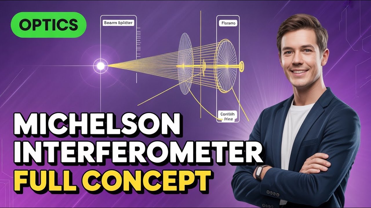
The standard experimental setup of the Michelson Interferometer (mirrors, beam splitter, and light source).
Michelson Interferometer || Full concept || part 1
281
The Michelson Interferometer setup includes: (1) Monochromatic light source emitting single wavelength light, (2) Convex lens that collimates light to make it parallel, (3) Partially reflecting glass plate (beam splitter) at 45 degrees that divides light amplitude, (4) Two mirrors (M1 and M2) at 90 degrees to each other, and (5) Compensating glass plate ensuring equal optical path lengths. The light from the source passes through the lens, then hits the beam splitter where part reflects and part transmits. Both beams travel to mirrors, reflect back, and recombine at the beam splitter before reaching the detector.
Click to watch →
L 11 Optics & Lasers | Michelson Interferometer | A Wonderful Experimental Setup Used to find Ether
1.8K
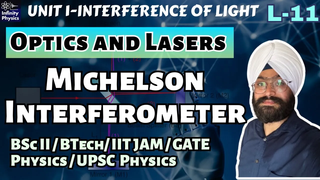
The Michelson interferometer consists of two perpendicular mirrors (M1 and M2), a partially silvered glass plate (beam splitter), and a compensating glass plate. The beam splitter divides incoming light into two beams: one reflected toward M1 and one transmitted toward M2. Both beams reflect back to the beam splitter, where they recombine and interfere. The compensating plate ensures both beams pass through equal glass thickness, matching their optical path lengths. Mirrors can be tilted using screws to adjust fringe shapes and moved vertically to change path differences.
Click to watch →

Michelson Morley Experiment | Unit-1 | L-10 | BSc 4th Semester Physics | Modern Physics | Relativity
3.1K
The Michelson interferometer consists of a light source, a half-silvered glass plate (beam splitter) at 45 degrees, two mirrors (M1 and M2), and a telescope for observation. Light from the source strikes the half-silvered plate and splits into two beams: one transmitted and one reflected. Each beam travels to a mirror, reflects back, and recombines at the beam splitter, creating interference fringes visible through the telescope. The interferometer is designed so that both light paths are equal in length.
Click to watch →

Krylov 2025 Optics 20
108
The Michelson interferometer consists of a light source, beam splitter, two mirrors, and observation screen. A collimating lens produces parallel rays, and an objective lens focuses them for observation. The beam splitter creates a virtual image of one mirror, making light appear to reflect from two parallel surfaces. For interference, the real mirror and its virtual image must be strictly parallel within angular tolerance λ/D. Fringes of equal inclination are observed in the focal plane, while fringes of equal thickness appear when the screen is displaced beyond focus. Extended sources produce magnified images covered with fringes. The interferometer demonstrates energy conservation: destructive interference at a point redirects energy back toward the source.
Click to watch →

17. II BSc 3rd Sem - Physics - Wave Optics - Michelson Interferometer
20.5K
The Michelson Interferometer consists of: (1) A monochromatic light source, (2) A convex lens to collimate light into a parallel beam, (3) A semi-silvered glass plate G1 that splits light into reflected and transmitted rays, (4) Two perpendicular mirrors M1 and M2 mounted on leveling screws for precise adjustment, (5) Two parallel glass plates G1 and G2 of equal thickness and material, where G1's face toward G2 is silvered, and (6) A telescope for observing interference patterns. The mirrors are adjusted to be exactly perpendicular using the leveling screws.
Click to watch →
Deep Dive
The historical objective of the Michelson-Morley experiment regarding the detection of the 'luminiferous aether'.

Teoría de la Relatividad, Parte 1
1.6M
In 1887, Albert A. Michelson and Edward W. Morley conducted an experiment to detect Earth's motion through the hypothetical 'luminiferous aether' (the supposed medium through which light was thought to travel). According to the aether hypothesis, Earth's orbital motion around the Sun (about 30 km/s) should affect measured light speed—light traveling in the same direction should measure 303,000 km/s, while light traveling in the opposite direction should measure 297,000 km/s. This would reveal Earth's motion through the aether. The experiment used an interferometer to measure light speed in two perpendicular directions, expecting to detect this difference.
Click to watch →

Tim Maudlin: A Masterclass on Special Relativity
161.2K
At the end of the 19th century, physicists believed electromagnetic waves needed a material medium called the luminiferous ether, analogous to how sound waves require air. The Michelson-Morley experiment was designed to detect Earth's motion through this ether by measuring tiny differences in light speeds in different directions. However, the experiment found no such difference—a null result. This puzzle contributed to the development of special relativity, though Einstein was not primarily motivated by this experiment. The failure to detect ether wind was a major puzzle that contributed to the development of special relativity.
Click to watch →
Everything and Nothing: Part 2, "Nothing" 4k
862.1K
Albert Michelson and Edward Morley conducted one of physics' most famous experiments to detect the luminiferous aether, a hypothetical medium thought to carry light waves. Their apparatus used a beam splitter and mirrors to compare light beams traveling perpendicular to each other. Despite requiring detection of differences one part in a hundred million, they found no evidence of the ether. Light always traveled at the same speed regardless of direction. This negative result proved that the ether doesn't exist and that light can propagate through truly empty space. The development of practical vacuum technology then enabled revolutionary discoveries including X-rays, electrons, and atomic structure, giving rise to quantum mechanics.
Click to watch →

Michelson–Morley Experiment introduction | Special relativity | Physics | Khan Academy
299.4K
The Michelson-Morley experiment, conducted in 1887, attempted to detect the luminiferous ether—a hypothetical medium through which light waves were thought to propagate—by measuring differences in light speed when light traveled in different directions relative to Earth's motion through space; however, the experiment found no detectable difference in light speed regardless of orientation or time of year, leading to the conclusion that the luminiferous ether does not exist and that light travels at a constant speed independent of its direction of propagation.
Click to watch →

Michelson Morley Experiment! #bedkdian #mjpru #bsc3rdyear #physics
131.5K
The Michelson-Morley experiment (1887) tested the existence of 'luminiferous ether,' a hypothetical medium through which light was believed to propagate. The experiment used an interferometer with a half-silvered glass plate that split a monochromatic light beam into two perpendicular paths, each reflecting off mirrors and recombining to create interference fringes. Scientists expected that Earth's motion through the ether would cause different travel times for light in the two directions, resulting in observable fringe shifts when the apparatus was rotated. However, no fringe displacement was observed regardless of orientation, leading to the conclusion that no ether medium exists in space. This null result was pivotal in the development of Einstein's theory of special relativity, which eliminated the need for an absolute reference frame.
Click to watch →
Deep Dive
The distinction between geometric ray optics (idealized single rays) and physical wave optics (extended wavefronts).
PH II - 39 Optik, Grundbegriffe
17.3K
Optics is divided into geometric (ray) optics and wave optics based on object size relative to light wavelength. Geometric optics applies when objects are much larger than visible light wavelength (~500 nm), allowing light to be treated as rays traveling in straight lines. Wave optics becomes necessary when objects are comparable to or smaller than the wavelength, explaining phenomena like interference and diffraction that ray optics cannot predict. This distinction is analogous to the relationship between classical mechanics and quantum mechanics.
Click to watch →

Introduction au cours Physique 3
1K
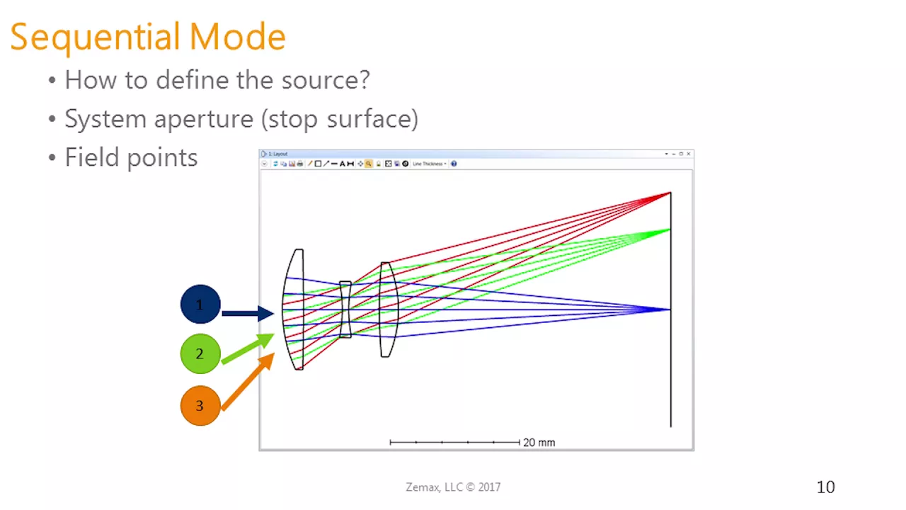
Light can be represented as wavefronts or rays perpendicular to wavefronts. The key distinction between geometric and physical optics lies in the ratio between optical element dimensions and wavelength. When dimensions are much larger than wavelength (like typical lenses with 25-50 mm diameter), light travels in straight lines without diffraction. When dimensions are comparable to wavelength, diffraction occurs, causing angular spreading of light. This ratio determines which optical theory applies: geometric optics for large dimensions, physical optics for wave phenomena.
Click to watch →
OpticStudio Frequently Asked Support Questions - April 6th 2016
9.5K
Geometric rays travel in straight lines, maintaining constant beam size and divergence, but Gaussian beams always diverge or converge. Two approximations allow ray tracing: within the Rayleigh range (slow size change, collimated approximation), and far from it (linear size change, point source approximation). Physical optics propagation is required when: (1) beams reach intermediate foci near truncating optics (pinholes), where diffraction prevents perfect focusing; (2) diffraction effects far from focus are important (other modes only work at focus); (3) propagation is long with nearly collimated beams (actual beams diverge faster outside Rayleigh range). It models wavefronts with complex amplitude arrays (amplitude and phase), user-definable dimensions and sampling.
Click to watch →

Video covering Knight 34.1 - (the first half of) 34.3
1.1K
Ray optics (geometric optics) focuses on the particle nature of light, treating light as traveling in straight lines called rays. This contrasts with wave optics, which focuses on properties of light that depend on its wave nature, such as interference and diffraction. In ray optics, we can draw pictures imagining light traveling along specific paths, which simplifies the analysis of reflection and refraction phenomena.
Click to watch →

2413.wmv
147
This section explains the relationship between ray optics (geometric optics) and wave optics. Ray optics describes light as traveling in straight lines and reflects off surfaces according to the law of reflection. Wave optics describes light as an electromagnetic wave that can interfere and diffract. Ray optics is an approximation that works when the features of the system are much larger than the wavelength of light. When features are comparable to the wavelength, wave optics effects become important. The law of reflection can be derived from wave optics by considering the interference of waves from different points on the reflecting surface. The mathematical derivation shows that ray optics emerges as the limit of wave optics when the wavelength is much smaller than the characteristic dimensions of the system.
Click to watch →
Prerequisite Knowledge
- Concept 01Basic principles of wave optics, including wave interference, phase difference, and path length difference.
- Concept 02The standard experimental setup of the Michelson Interferometer (mirrors, beam splitter, and light source).
- Concept 03The historical objective of the Michelson-Morley experiment regarding the detection of the 'luminiferous aether'.
- Concept 04The distinction between geometric ray optics (idealized single rays) and physical wave optics (extended wavefronts).
Subsequent Learning
- Step 01Mathematical derivation of fringe patterns of equal inclination (Haidinger fringes) and equal thickness (Fizeau fringes).
- Step 02How the null result of the Michelson-Morley experiment laid the groundwork for Einstein's Theory of Special Relativity.
- Step 03Modern applications of Michelson interferometry, such as gravitational wave detection in LIGO.
- Step 04Analysis of other interferometer configurations, such as the Mach-Zehnder and Fabry-Pérot interferometers.
Interference Setup
Zero Path Difference
Fringe Formation
Interference Setup
0:05Playing Section
- 1
Explains Michelson-Morley experiment with beam splitter and two mirrors.
- 2
Clarifies that two beams travel different paths and interfere.
Dayton Miller's Thermal Distortion Critique
While standard wave optics attributes the formation and shift of interference fringes in the Michelson-Morley experiment to controlled geometric path differences (such as slight mirror misalignments), physicist Dayton Miller offered a critical alternative perspective. Miller argued that the apparatus was highly susceptible to minute temperature gradients in the surrounding air and the structural frame. According to his critique, these thermal fluctuations alter the refractive index of the air paths and cause microscopic expansions in the apparatus arms. This produces fringe variations and shifts that can be mistaken for—or completely mask—the theoretical effects being measured, challenging the assumption that fringe behavior is purely a function of clean optical alignment and relative motion.
Deep Dive
Mathematical derivation of fringe patterns of equal inclination (Haidinger fringes) and equal thickness (Fizeau fringes).

Wave and Optics(Lecture#06): Fringes of equal thickness and Fringes of equal inclination
11.1K
In thin film interference, fringes of equal thickness are formed when light reflects off a thin transparent film with varying thickness, creating interference patterns where the path difference depends on the film's thickness; conversely, fringes of equal inclination are formed when light strikes the film at different angles, causing interference patterns where the path difference depends on the angle of incidence rather than the film's thickness.
Click to watch →

📚TGT/ PGT/GIC 🏆 Physics 🏃 Optics #16(A)🔥 Interference-2| Newton's Ring, Michelson Interferometer..
14.4K
The fringe pattern in Michelson Interferometer depends on mirror orientation. Parallel mirrors produce circular fringes (Haidinger fringes). Inclined mirrors produce straight-line fringes (Fizeau fringes). Larger angles produce hyperbolic fringes. Conditions: Bright fringes when 2d cosθ = nλ, dark fringes when 2d cosθ = (n + 1/2)λ. These conditions determine constructive and destructive interference.
Click to watch →
Lecture 15 (3rd Semester) - Haidinger & Fizeau Fringes
36.6K
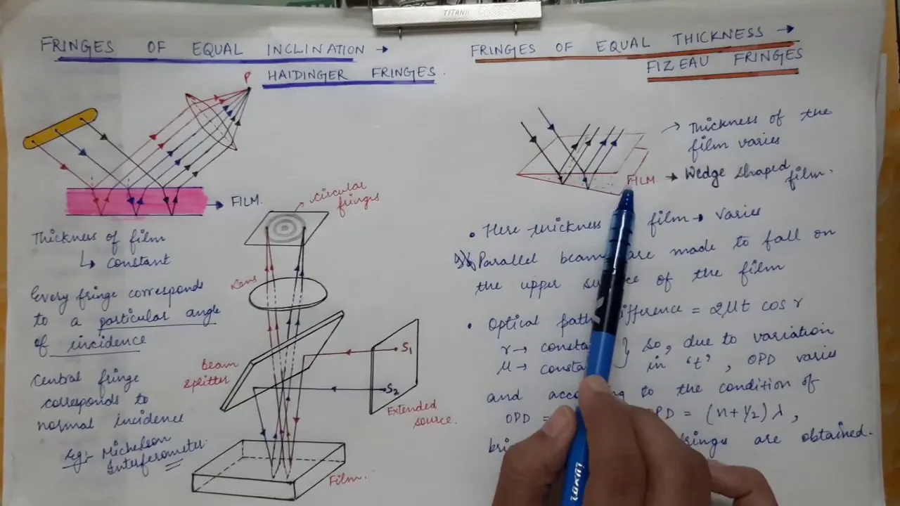
In division of amplitude interference, light is split into two coherent beams that travel different paths before recombining to create interference patterns. Haidinger fringes (fringes of equal inclination) occur when light reflects off a thin film at varying angles, producing concentric circular patterns due to path difference dependent on angle of incidence. Fizeau fringes (fringes of equal thickness) appear when light passes through or reflects from surfaces with varying thickness, creating straight-line patterns where path difference depends on physical thickness variations. Both types demonstrate the wave nature of light through constructive and destructive interference.
Click to watch →

Haidinger Fringes || Interference -- 6
25.6K
Haidinger fringes, also known as fringes of equal inclination, are concentric circular interference patterns formed when light reflects from a thin transparent film; these fringes occur because light waves reflected from the top and bottom surfaces of the film travel different paths and interfere constructively or destructively depending on their phase relationship, with the visibility being highest for equal inclination angles.
Click to watch →

Haidinger Fringes | Fizeau Fringes | Optics | Physics | BSc | Btech | UPSC | GATE | JEE | NEET
11.2K
Haidinger fringes (circular fringes with equal inclination) are formed when light passes through a transparent plate with uniform thickness, requiring equal angles of incidence and circular ray paths, while Fizeau fringes are formed in variable thickness films (like air wedges) where interference occurs directly on the surface; both phenomena result from amplitude division but differ in their geometric requirements and observable locations.
Click to watch →
Deep Dive
How the null result of the Michelson-Morley experiment laid the groundwork for Einstein's Theory of Special Relativity.

Kis-Tóth Ágnes: Randevú a Kozmosszal (Atomcsill, 2025.10.02.)
63K
The Michelson-Morley experiment produced a null result—no difference in the speed of light was detected regardless of Earth's direction of motion. This was baffling because it contradicted the aether hypothesis and suggested that the speed of light is constant in all reference frames. This result became one of the most important experiments in physics history, as it provided crucial evidence for Einstein's theory of relativity.
Click to watch →

Özel Görelilik | 80, 81 ve 82. Gün | 2026 | 90 Günde AYT Fizik Kampı
12.7K
The Michelson-Morley experiment (1887) tested whether light requires an invisible medium called 'ether' to propagate through space. Scientists believed ether existed because sound and water waves need media. The experiment used an interferometer to detect ether 'winds' by measuring light speed differences in different directions. Despite 42 years of repeated experiments at different locations and times, no interference fringe shifts were observed. This 'null result' proved that light travels through vacuum without any medium, and that light speed is constant regardless of the motion of the source or observer. Einstein's special relativity, published in 1905, is built on two fundamental postulates: (1) The laws of physics are identical in all inertial reference frames. (2) The speed of light in a vacuum is constant and independent of the motion of the light source or observer. These postulates contradict Galilean relativity, where velocities add up. For light, this doesn't work—light always travels at c regardless of the source's motion. This leads to revolutionary consequences: time and space are not absolute but relative to the observer's motion. Length contraction states that objects moving at speeds close to the speed of light appear shorter in the direction of motion. Time dilation states that time appears to pass more slowly for objects moving at speeds close to the speed of light. The twin paradox involves two twins: one travels at high speed to a distant star and returns, while the other remains on Earth. According to time dilation, the traveling twin should be younger upon return. The paradox is resolved by recognizing that the traveling twin undergoes acceleration, which breaks the symmetry between the two reference frames.
Click to watch →
Física IV - Pgm 19 - Teoria da relatividade restrita II - Parte 1
25.8K
The Michelson-Morley experiment (1881, refined in 1887) was designed to detect Earth's motion through the hypothetical aether by measuring the speed of light in different directions. Using an interferometer, the experiment split light into two perpendicular paths, reflected them back, and recombined them to observe interference fringes. If Earth moved through the aether at approximately 30 km/s, the expected fringe shift was about 0.4 fringes, well within the experiment's precision of 0.01 fringes. However, the result was null - no fringe shift was observed. This null result contradicted the aether hypothesis and forced physicists to develop new explanations, including length contraction (FitzGerald-Lorentz contraction) and eventually Einstein's special relativity.
Click to watch →

The Terrifying Truth About What Waits Beyond Light Speed
2.1K
By the 1880s, physicists believed light required a medium called the luminiferous ether, similar to how sound needs air. They expected Earth's motion through this ether would create an 'ether wind' affecting light's speed. Albert Michelson and Edward Morley built an interferometer to detect this effect by splitting light into two perpendicular beams and recombining them to observe interference patterns. Despite rotating the apparatus and testing at different times of day and seasons, they found no difference in light's speed in any direction. This 'null result' was one of the most famous in science, suggesting no ether existed and that light's speed is constant regardless of observer motion. The speed of light does not depend on how you are moving—whether you run toward a light beam or away from it, you still measure the same 300,000 km/s. In 1905, Albert Einstein published his theory of special relativity based on two postulates: the laws of physics are the same for everyone moving steadily with no acceleration, and the speed of light in empty space is the same for every observer, no matter how they are moving or how the source is moving. This leads to a profound inversion—speed is just distance divided by time, so to hold that one ratio fixed for observers in violent disagreement about their own motion, the distance and the time themselves must bend. The measuring sticks and the ticking clocks are the things that flex so that the speed of light can stay the one solid rock beneath them. Before Einstein, time and space were a fixed stage, absolute and universal. Einstein swapped their roles—the speed of light became the absolute, and time and space became the flexible quantities that protect it.
Click to watch →
Die Lichtgeschwindigkeit Teil 2/2 – Antwort an Robert ToFalls Versuch, Einstein zu widerlegen!
43.7K
This section details how wave interference principles enabled the Michelson-Morley experiment and produced its groundbreaking null result. When coherent light waves recombine after traveling different paths, constructive interference creates bright fringes while destructive interference produces dark fringes. The experiment expected that Earth's motion through aether would cause path length differences proportional to velocity squared, producing observable fringe shifts. However, no such shifts were detected—the interference pattern remained constant regardless of Earth's rotational direction. This null result contradicted aether theory but provided crucial evidence for Einstein's later development of special relativity.
Click to watch →
Deep Dive
Modern applications of Michelson interferometry, such as gravitational wave detection in LIGO.

Оптика Л13. 2024. Временная и пространственная когерентность. Интерферометры
136
The Michelson interferometer consists of a light source, a beam splitter at 45°, two mirrors at the ends of two arms, and a detector. Light is split by the beam splitter, reflected by mirrors, and recombines to produce interference fringes. The path difference between arms determines the interference pattern. Applications include measuring refractive indices of gases or liquids by placing samples in one arm and observing fringe shifts. The interferometer was used in the original ether-drift experiment and is now used in modern gravitational wave detectors like LIGO, where arms are several kilometers long to detect tiny changes in distance caused by passing gravitational waves.
Click to watch →

Lecture 24 : Michelson Interferometer and Its Applications - I
20.6K
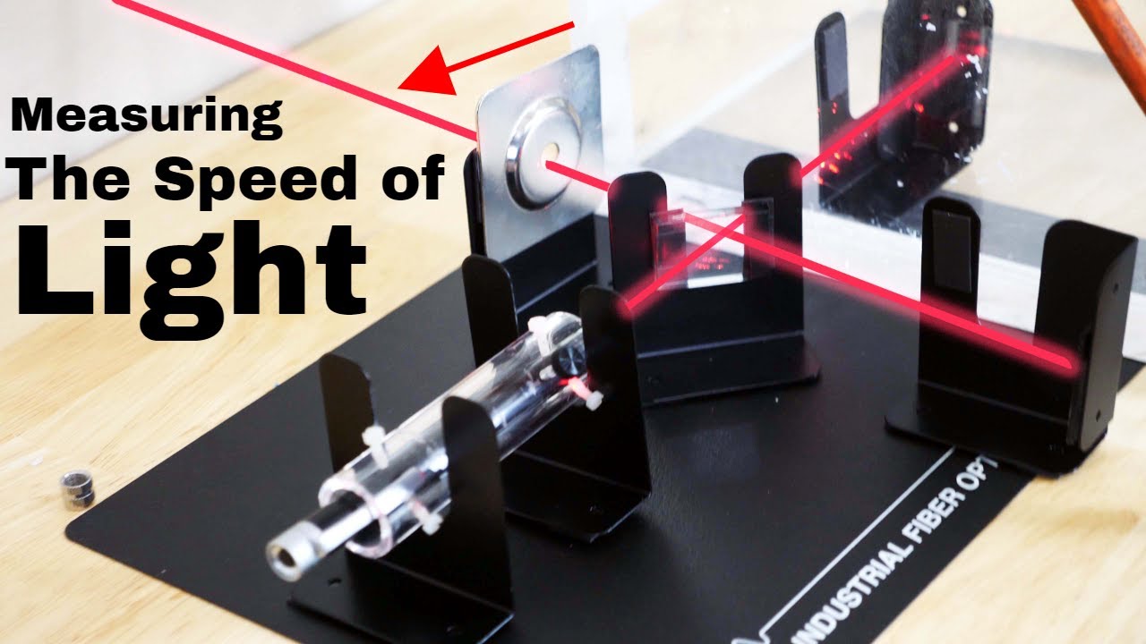
The Michelson interferometer, invented by Albert Abraham Michelson (Nobel Prize 1907), is a fundamental optical instrument that splits a light beam using a semi-silvered beam splitter, reflects each beam off mirrors, and recombines them to create interference fringes; it operates on the principle of interference by division of amplitude, requiring mutually coherent beams from a single source, and can measure distances, wavelengths, and refractive indices with high precision, with applications ranging from the famous Michelson-Morley experiment to modern gravitational wave detection by LIGO.
Click to watch →
The Most Famous Failed Experiment
191.7K
The same interferometric principles used in basic refractive index measurements have been scaled up dramatically for detecting gravitational waves. Modern gravitational wave detectors like LIGO use interferometers with path lengths of several miles instead of just inches. When gravitational waves pass through Earth, they cause tiny distortions in spacetime that stretch and compress the path lengths of light in the interferometer arms by incredibly small amounts—on the order of a fraction of a proton's diameter. These minuscule changes cause the interference fringes to shift slightly, which can be detected and analyzed to determine the strength and characteristics of the passing gravitational wave. This application demonstrates how interferometry provides extremely sensitive measurements of distance changes.
Click to watch →

Optics | Important Questions | Complete Revision | iSTUDY Online
57K
In the Michelson interferometer, interference fringes are formed when beams recombine. Fringes are circular when mirrors are parallel and straight when one mirror is tilted. Applications include measuring wavelength, measuring small distances, measuring refractive index of gases, testing optical surfaces, and detecting gravitational waves.
Click to watch →
How does LIGO detect gravitational waves?
26.2K
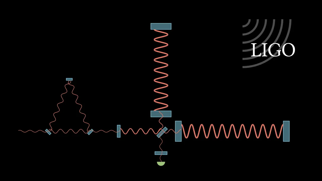
A Fabry-Perot interferometer uses two well-aligned mirrors separated by distance l. At resonance (cavity length equals half-integer wavelength), standing waves form causing massive intracavity power buildup. The cavity gain derives from an infinite geometric series representing multiple internal reflections. Resonance condition requires accumulated phase equal to integer multiples of 2π. Complex cavity reflection coefficient describes reflected beam behavior, becoming zero at resonance. Highly reflective mirrors create extreme sensitivity to length changes, with the denominator squared in sensitivity expressions providing enormous amplification. A Michelson interferometer uses a central 50/50 beam splitter dividing input into X and Y arms, each with highly reflecting mirrors. Only differential motion between arms changes power distribution between ports; common motion creates phase shifts without affecting power. Basis transformation to common and differential coordinates simplifies analysis. A Fabry-Perot Michelson combines both technologies, replacing standard end mirrors with Fabry-Perot cavities. Combining Michelson transmissivity with Fabry-Perot length response yields the transmitted power expression. With four-kilometer arms, one-picometer differential offset, one-kilowatt input power, and highly reflective mirrors, gravitational wave differential motion is amplified by orders of magnitude, rendering previously undetectable signals observable.
Click to watch →
Deep Dive
Analysis of other interferometer configurations, such as the Mach-Zehnder and Fabry-Pérot interferometers.

How to Build Interferometers - A Visual Guide
5.3K
This final section presents advanced interferometer configurations. The Mach-Zehnder interferometer offers a single-pass design preventing double traversal of test optics, providing superior dynamic range for high-power measurements compared to double-pass Twyman-Green systems. Higher power test optics produce more pronounced interference patterns with greater fringe contrast. The Pohl interferometer demonstrates simple interference using laminate sheets at glancing angles, creating visible interference patterns through scattered light. The section concludes by summarizing the complete spectrum of interferometer types—from basic double-slit demonstrations to sophisticated precision metrology tools—emphasizing how each configuration serves specific measurement needs in optical testing and metrology applications.
Click to watch →

Faster than Light: Warp Drive - SpaceVision 2013
1.2M
A Fabry-Pérot interferometer differs from a Michelson interferometer in that it uses multiple passes of light through a series of mirrors, greatly increasing the interference pattern resolution. While a Michelson interferometer shows basic Newton rings, a Fabry-Pérot can reveal subatomic structure by showing separation in fringe lines, similar to how you can see individual spectral lines in sodium rather than just a combined doublet. This real-time averaging capability makes it advantageous for detecting subtle changes in optical properties caused by quantum vacuum effects.
Click to watch →
Mach Zehnder Interferometer || Full concept ||one shot || Engineering Physics
1.2K
This comprehensive analysis examines how light beams acquire different phases through the Mach-Zehnder interferometer's optical paths. For detector D1, both upper and lower paths accumulate identical total phases: the upper path includes one reflection (π phase shift) and one glass traversal, while the lower path includes two traversals and two reflections. All terms cancel, yielding Δφ = 0, which corresponds to constructive interference. For detector D2, the upper path includes one reflection and two traversals, while the lower path includes two reflections and two traversals. The net phase difference is π radians, corresponding to destructive interference. These mathematical derivations explain why detector D1 always shows bright fringes while D2 always shows dark fringes, regardless of experimental conditions.
Click to watch →
Fabry Perot Interferometer
100.8K
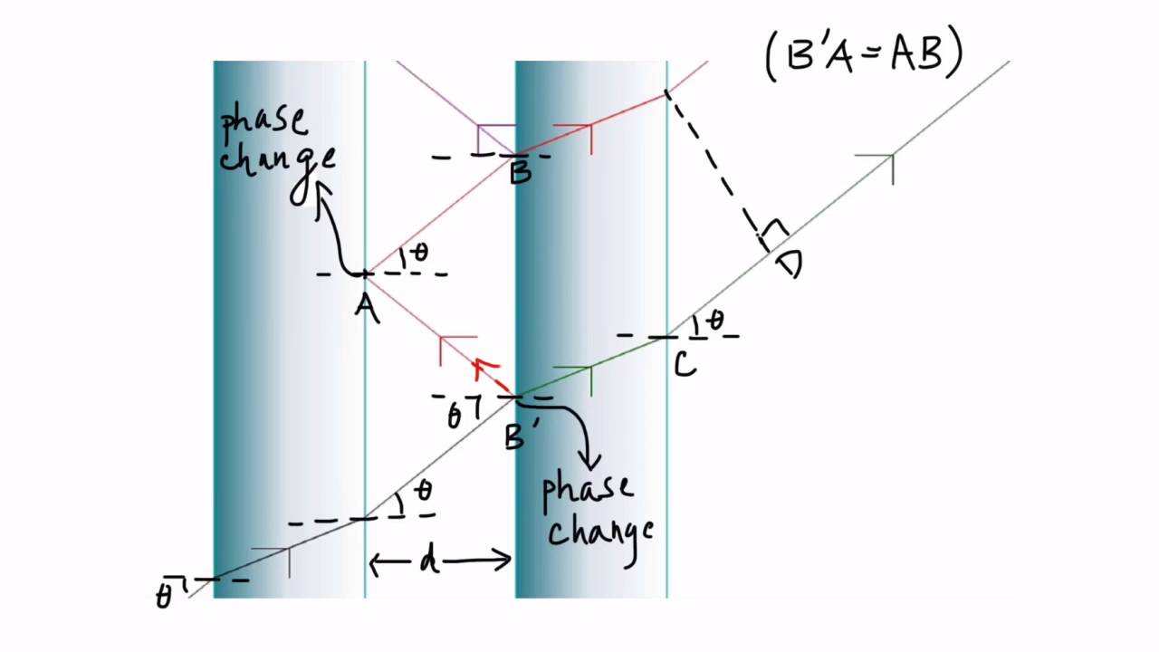
The Fabry-Pérot interferometer, developed in 1899 by Charles Fabry and Alfred Pérot, is a multiple-beam interferometer using monochromatic light with applications in telecommunications, spectroscopy, and astronomy. It consists of two closely separated parallel partially silvered mirrors that split light through amplitude division at each reflection. Each reflection causes amplitude distribution and a half-wavelength phase shift when reflecting from a more optically dense medium. Multiple reflections create path length differences that produce interference patterns on a screen. Bright and dark bands result from constructive and destructive interference, with complete constructive interference producing the brightest bands. The path difference equals 2Dcosθ, requiring integer wavelengths for constructive interference. This enables wavelength determination and monochromatic light testing. Interferometers measure small distances, refractive index changes, and surface irregularities, with LIGO using them to detect gravitational waves by extending light-matter interaction time.
Click to watch →
Les instruments (et filtres) solaires H-alpha
7.1K
The Fabry-Pérot interferometer operates on wave interference principles, using two parallel plates separated by precise distances to create constructive and destructive interference patterns. Adjusting plate separation tunes the transmitted wavelength. Three main etalon types exist: tiltable/inclinable etalons for rapid tuning, heated etalons for thermal stability, and integrated blocking filter versions. Double stack configurations place two etalons in series, achieving narrower effective bandwidths (0.3-0.5nm) than single etalons. Specialized telecentric extenders convert converging telescope beams to parallel rays, eliminating angular dispersion effects that cause wavelength variations across the field of view. Optimal performance typically requires F30+ focal ratios. Pressure-tuned etalons use adjustable air gaps for immediate wavelength adjustment but require 5-10 minutes thermal stabilization between changes.
Click to watch →
Interference Setup
Zero Path Difference
Fringe Formation
Interference Setup
0:05- 1
Explains Michelson-Morley experiment with beam splitter and two mirrors.
- 2
Clarifies that two beams travel different paths and interfere.
Dayton Miller's Thermal Distortion Critique
While standard wave optics attributes the formation and shift of interference fringes in the Michelson-Morley experiment to controlled geometric path differences (such as slight mirror misalignments), physicist Dayton Miller offered a critical alternative perspective. Miller argued that the apparatus was highly susceptible to minute temperature gradients in the surrounding air and the structural frame. According to his critique, these thermal fluctuations alter the refractive index of the air paths and cause microscopic expansions in the apparatus arms. This produces fringe variations and shifts that can be mistaken for—or completely mask—the theoretical effects being measured, challenging the assumption that fringe behavior is purely a function of clean optical alignment and relative motion.
Basic principles of wave optics, including wave interference, phase difference, and path length difference.
The standard experimental setup of the Michelson Interferometer (mirrors, beam splitter, and light source).
The historical objective of the Michelson-Morley experiment regarding the detection of the 'luminiferous aether'.
The distinction between geometric ray optics (idealized single rays) and physical wave optics (extended wavefronts).
Mathematical derivation of fringe patterns of equal inclination (Haidinger fringes) and equal thickness (Fizeau fringes).
How the null result of the Michelson-Morley experiment laid the groundwork for Einstein's Theory of Special Relativity.
Modern applications of Michelson interferometry, such as gravitational wave detection in LIGO.
Analysis of other interferometer configurations, such as the Mach-Zehnder and Fabry-Pérot interferometers.
73.1K views1.9Klikes4:25@hcverma2928Original Release: 2019-01-10
while talking of Michaelson morle experiment we say that uh fringes are formed in the in the view of this telescope now I have gotten this question from several students that if the two paths on the two sides are same and the phase difference is zero how come fringes are forming why there should be a bright and dark if the face difference is zero should only be bright so let me answer this question and before that let me once again tell what is that Michaelson worldly experiment itself so essentially what you have is a light coming and then light falling on a plate a plate from where part of it is reflected and then part of it is refracted it's very thin so there's a too much of exaggeration that I'm showing this uh uh shift then you have a mirror here then you have a mirror here and this mirror reflects the light which comes here and then part of it is reflected and part of it is going into it similarly this mirror reflects call it M2 M1 this is M2 this mirror reflects and that comes here part of it is deflected and part of it is transmitted and it is these are the Rays which we are talking one coming from uh this side one coming from this side it's going coming and then reflecting from here a part is also refracted but anyway that goes west and then the other one is this one which is going and then reflecting and then coming and then part of it is reflected but we are concerned with this one so these two beams which have come through two different paths they interfere in actual design you also have a compensating plate because it one beam is going through this thickness the other is not but those things are not much important for this discussion now if the total path traveled in this direction the total path traveled in this direction if they happen to be exactly same if they happen to be exactly same yes the phase difference is zero and you should got a bright there but then what I have shown here is just one Ray One One path whereas the telescope has its own field of view its own field of view so you you not only see what is here you also see what is here or what is here or what is here or what what is here so the light which is coming from here is not one single Ray of course it is a beam and that beam is going and that whole beam is going here reflecting reflecting some parts of that beam will have a path so that it will reach here some path will be there so that it reaches here so at this place at this place beam coming from first path beam coming from second path will have a different phase relation whereas in this place they will have a different phase relation this place they will have a different pH phase relation and so on therefore when you see this big view that means you are seeing a an aparture not a single Ray but an aparture a beam and uh different places will receive beams which are from different portions and they have covered different path geometric path will be different so at some places you will have bright fringes where the path differences are integral multiple of Lambda or phase difference is integral multiple of 2 pi and then other places you will have dark where the phase difference is pi 3 Pi odd multiples of Pi so that is how the fringes are formed
Up Next

8:59
Special Relativity Explained: Time Dilation and Length Contraction
@crashcourse
1.4M views•2017-02-23

12:53
21cm Hyperfine Transition in Neutral Hydrogen: Radio Astronomy Basics
@AaronRobertParsons
12.4K views•2011-10-13

32:32
NMR Spin Physics I: Zeeman Effect, Resonance Condition & Larmor Frequency
@nptel-indianinstituteofsci8064
2.3K views•2024-01-17

27:14
Entropy and the Second Law of Thermodynamics Explained
@veritasium
27.5M views•2023-07-01
Related Study Plans & Knowledge Roadmaps
Structured learning paths in Physics
physics
Nuclear Physics (Decay, Fission & Reactors)
01Atomic Structure and the Binding Force
02Radioactive Decay and Half-Life
03Nuclear Fission Mechanics and Chain Reactions
+ 2 more learning modules
12h5 modules
Explore Roadmap
physics
Soft Matter (Polymers, Colloids & Rheology)
01Foundations of Soft Matter & Thermal Forces
02Polymer Physics and Macromolecules
03Colloids, Surfactants, and Self-Assembly
+ 2 more learning modules
38h5 modules
Explore Roadmap
physics
Analytical Mechanics: Lagrangian & Hamiltonian
01Mathematical Foundations: Calculus of Variations
02From Newtonian Mechanics to Constraint Dynamics
03The Principle of Least Action & Lagrangian Mechanics
+ 3 more learning modules
28h6 modules
Explore Roadmap
physics
General Relativity (Spacetime & Cosmology)
01Foundations of Relativity: Special Relativity
02The Geometry of Spacetime: Equivalence Principle & Curvature
03Einstein's Field Equations: The Mathematics of Gravity
+ 2 more learning modules
55h5 modules
Explore Roadmap