






![#2 Instrucciones Básica [ pinMode, digitalWrite, delay ] - Curso Arduino 💻](https://i.ytimg.com/vi/dwet3or5rmQ/maxresdefault.jpg)

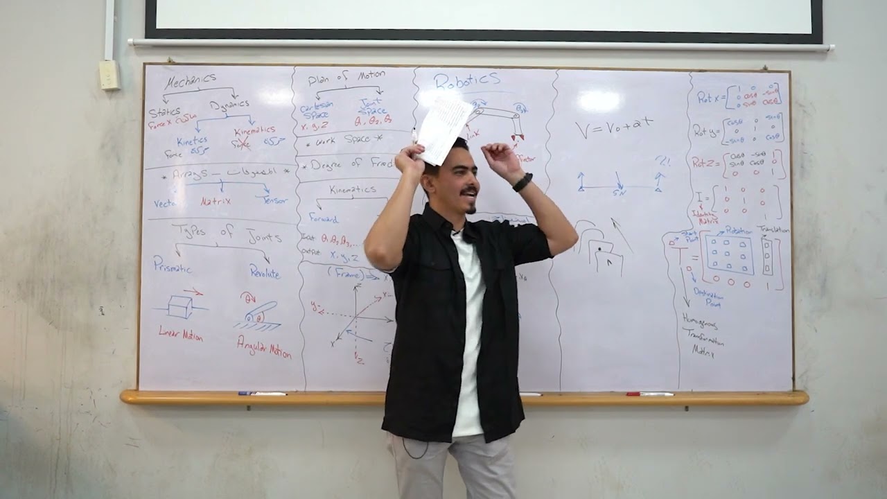
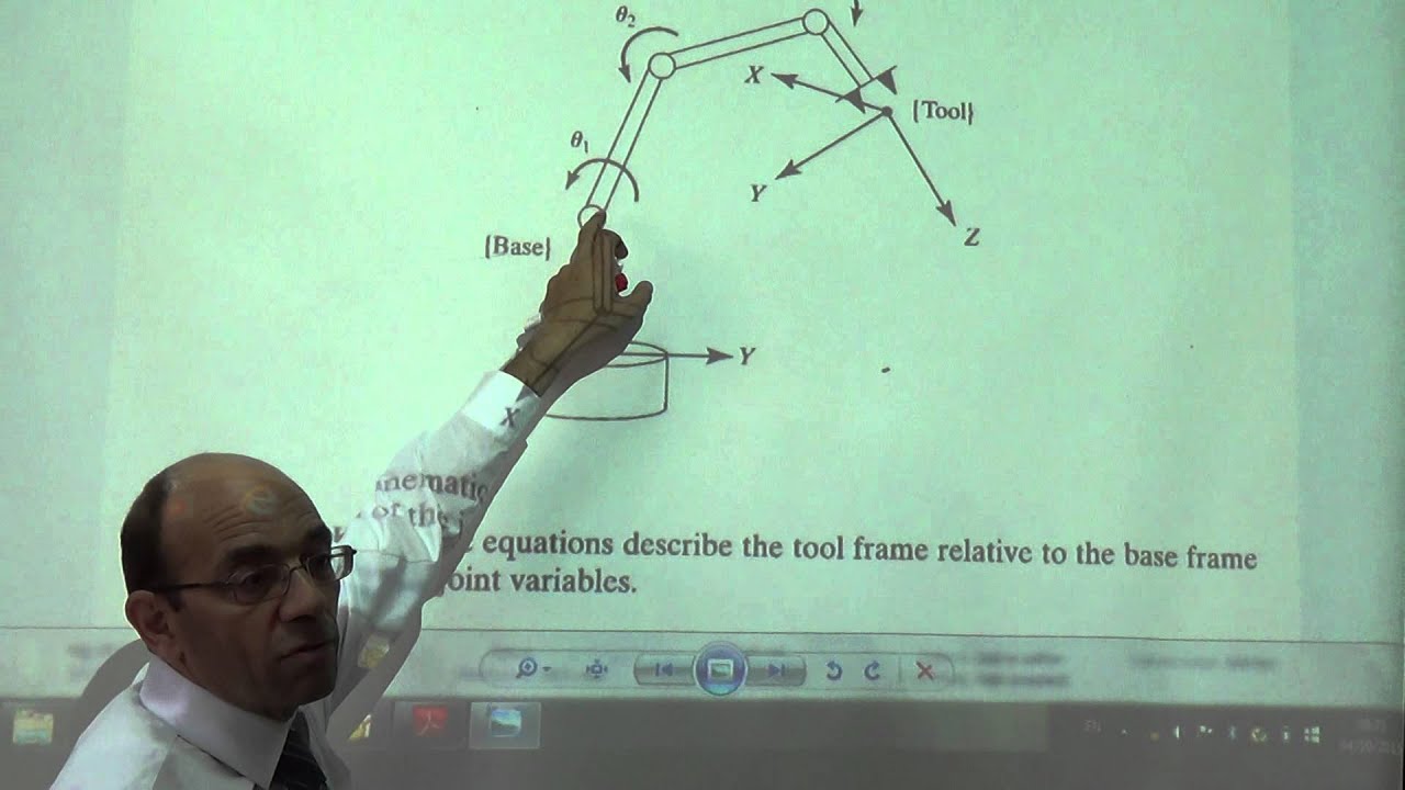









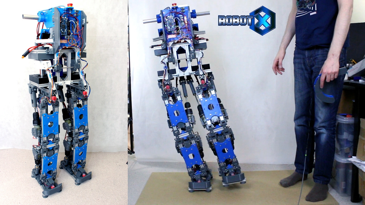


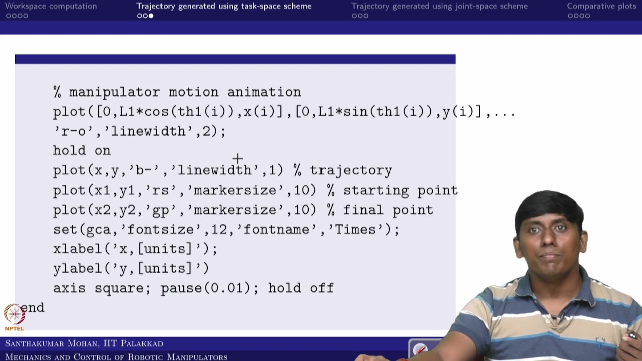


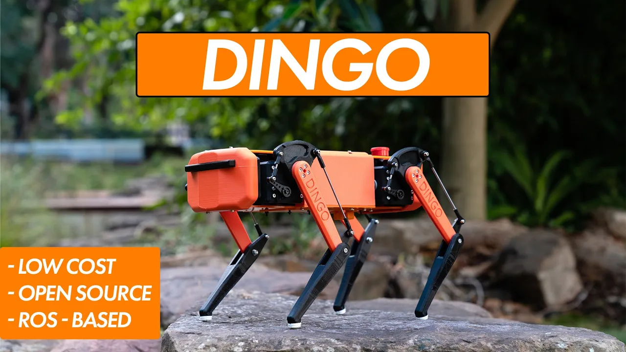

Inverse kinematics enables precise control of multi-jointed robot limbs by calculating joint angles from desired end-effector positions; for a quadruped robot, this involves solving geometric relationships using trigonometry (such as SSS triangle solutions with inverse cosine) to translate Cartesian coordinates into motor commands, allowing the robot to move its feet in straight lines and achieve complex motions like walking by coordinating multiple joints simultaneously.
Inverse Kinematics for 3D-Printed Robot Dog | XRobots Tutorial
Added:Fundamental trigonometry and coordinate geometry, specifically the Law of Cosines and vector operations in 3D Cartesian space (XYZ).
Basic microcontroller programming, such as C/C++ in the Arduino environment, to implement mathematical equations and control hardware.
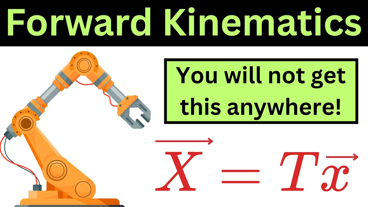
The concept of Forward Kinematics (FK) and how joint angles determine the position of a robot's end-effector.
Hardware fundamentals of robotic actuation, including servo motor operation, PWM (Pulse Width Modulation) signaling, and joint limits.
Gait planning and locomotion algorithms (e.g., trot, walk, bound) to coordinate multiple legs for fluid, stable movement.
Integration of Inertial Measurement Units (IMUs) for dynamic self-balancing and real-time posture correction on uneven terrain.
Advanced trajectory generation and path planning to smooth out leg movements and minimize mechanical stress.
Introduction to ROS (Robot Operating System) and simulation tools like Gazebo or Webots to model quadruped behavior before physical deployment.
139.3K views6Klikes19:33Original Release: 2020-03-31
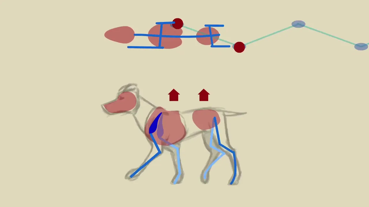
hello this is part four of mini dog the open-source quadrupedal robot it's mostly 3d printed and laid with servos an off-the-shelf parts and I've geared those servos down and we also have compliance in the joints with Springs and magnets and Hall effect sensors that can sense the load on each joint to make it more dynamic so check out the last few videos on that including part one which was my test leg so in this video we're going to do the kinematic model which involves integrating the remote control so we get three axis of translation and three axis of rotation we need to do that before we can make it walk so that we can translate the beat in Cartesian coordinates in Xyz space and work those joints back to the complex angles we've got for the three motors in the joints so that we can move those legs in any axis we want in straight lines which means as it works we can get those legs to move perfectly backwards and that's gonna make it much easier to make it balance the remote control I'm using is the good old open dog stroke sonic the hedghog remote which is why it says sonic remote on it and it's an Arduino make up with an n RF 24 lo1 transceiver chip in it for the radio we've got various switches and buttons and two three axis joysticks which move in these axis and they also rotate and that means we can do three axis of translation and three axis of rotation before we go and install the radio chip in the dog and get the data from the remote on there this is just a quick add for ways you can support the channel and that really makes all the difference of the projects I have patreon and YouTube channel membership and if you sign up for those you can get access to all the videos up to a week early and also sneak peeks and pictures of what's coming up and be part of that discussion I've a merchandise store on the links in the description to this video where you can get t-shirts bag socks and various other things with pictures of things I've made over the years on them there's also some affiliate links in the description for various services and if you sign up for those some of them are actually free trials it won't cost you any more but I'll get some money and that really helps support the channel right let's do some soldering so I'm a bit of creative wiring on my permit protoboard here is my NRF 24 lo1 that plugs in there and that breaks out the pins here to this piece of pin strip so that fits on top of my box where it was before we've got one connector here for the I squared C for the inertial measurement unit and we just need another wire now that takes SPI in there to our teensy to connect up the remote device so of why those connectors in I've put clear heat shrink on these pieces of solder terminals if you're wondering there the other one is white heat shrink and all that wise white in for all the SPI so now we should be to get that remote data slightly off with the electronics back in the box we've got a power supply smoothing capacitor decoupling capacitor because I found sometimes those in RF chips have problems with power supply issues so make sure the power supply is nice and sorted we can see we've got the IMU data still working there and we also now got all of our controls working including some switches I can switch on and off that should be giving us some digital bits on the end there so that seems to be working all right now a thresholded the stick so there is a bit of play in these sticks so i thresholded them so they do start at zero and count all the way up there's a dead spot of 50 either way on the analog in of that Arduino mega so we do get to zero in the middle and we don't get lots of noise on the controls I've also got a safety feature that means if the remote becomes disconnected then everything goes to zero so if I hold one of these sticks and pull out the power we should see we get a zero and a message saying there's no remote data which means we can put the robot into a safety mode and as soon as that comes back up and we should be good again so let's have a look at that in a serial plotter so we should see everything's at zero pretty much that's all of our sticks and we've got that IMU data as well for the pitch and for the roll sorry that seems to be working pretty well and we're ready to put that back into the dog so I've now tied up my remote so that we can control the modes of the robot so we should find that we've got no compliance here just the springs and if I turn on one of the switches here we should now find the compliance is back on using those Hall effect sensors to go and read the positions how much that spring is getting stretched essentially and how far the magnets are from the Hall effect sensor and we're using that to go and actively drive the joints to give it compliance so that works fine the rest of what we did last time is getting scrapped though and we'll make it walk again with a kinematic model so the first part of the kinematic model is going to be solving this leg length from the hip to the ankle and trying to move this ankle up and down in a perfectly straight lines they will notice the foot is directly below the shoulder join to the moments what we need to do is modify both the shoulder and the knee joints as we give it data or give it a length for this distance here so we can use trigonometry to work that out and that means we should be to move the robot up and down in a perfectly straight line without its feet sliding sideways and that's the first axis of our kinematic model so on paper that looks like a triangle which I've drawn in red here and we're gonna give the input is going to be this length here which we're gonna call Zed and that is the height of the robot from the ground now you'll notice the triangle doesn't quite converge on the actual point where the foot is touching the ground depending on the angle of the shin here that's going to be a different place I've just assumed that it's in the middle for now there'll be some error now cunningly this distance here and this distance here are both 125 millimeters they're both the same and that was part of the design because I knew I had to solve this model and that means all the angles in the triangle not only will they add up to 180 degrees as they do if any triangle but it means of this angle and this angle will be the same so as long as we can solve one of the angles in the triangle then we can easily work out the others because two of them are the same then we can do 180 degrees minus the other two and that gives us the one we haven't solved so we need to do is basically do some trigonometry to solve one angle and we know all three lengths of the triangle so this is pretty much high school mathematics but I'm using the website maths is fun comm to try and solve this because I can't remember how to do it even though I did it for open dog so this is the page for solving SSS triangles which means we know all three sides and we want to work out the angles and all the maths is here and what we need of course is to solve one angle so we can use this first example here which involves a bit of Pythagoras theorem by the look of it and finally some trigonometry and here it is encode so I've essentially gone through each stage and I've got a different variable for each stage so I can check it eventually we do an inverse cosine which gives us the angle now this angle is in radians which is what programming languages typically use so eventually we'll have to do a conversion into degrees so if we convert degrees to radians with this Google page we'll find one Radian is roughly 57 and a bit degrees two is 114 all these numbers look a bit weird until we get to a very familiar-looking number of pi 3.14159 to 7 and that's a hundred and eighty degrees so you'll remember me saying that we could get one eighty and take away the to offer angles to find the other one but of course is not 180 degrees it's 180 in radians which is pi so we're doing pi minus the other angle times two which the two angles the same and that then gives us both angles for the knee and the shoulder so then converted those two degrees so I can actually look at them and I've put those out to the serial terminal we're not going to look at that we can look at the real robot so then for each leg I've taken off the offset so the knee is already at 90 degrees and the shoulder is already at 45 and then I've multiplied that by a scaling factor and ice to get the microseconds value to actually drive the servo to the right angle on this leg which is the front left we're doing that in a positive manner and on the other leg which is the front right the leg is the other way round so we've actually inverted the scaler so the joints move the same way now the back it's the same and inverted again for the other back leg so I've now mapped the twist of the right hand stick to that leg length input so now as I turn that stick we should find those legs getting longer and shorter and it's calculating the trigonometry about a hundred times a second every time that loop goes round so should always remain with the foot perfectly under the shoulder now we do have a situation where the knee servo has to move further than the hip servo and both of these servos have motion filters on at the moment I'm actually filtering the servos individually rather than the actual Z demands and that means depending on how fast I move this obviously we exceed the maximum speed of the motor and one motor can get there faster than the other one so that means it doesn't necessarily move in a straight line and to do that we need to interpolate through every position on the way and drive it slow than the maximum speed of the motor but actually having checked this with a ruler and a protractor looks like my angles are correct and it looks like my leg moves to the right length and of course my robust compliance anyway so any minor errors get taken out in the natural flex in that compliancy there cause the result is that the robot go up and down and that's the first axis of our kinematic model so now that's done the next axis we're gonna do is moving the robot in a perfectly straight line in this direction so that means we want to move the foot back with some forwards along this line while keeping the shoulder exactly the same height so that means as the foot moves over here of course that height has to get longer so now we're going to feed the bit of mass we just did that calculates the leg length with this value and take this value from the stick so as we turn it the Roybal still goes up and down and that gives us the actual shoulder height this is an easy bit of trigonometry because it's a right angle triangle we know this piece which is the input we know this piece which is how far we want to move the foot so all we need to do is calculate the hypotenuse and the angle here so we can solve this with tangent and then sine or cosine so you can check it on math is fun if you want to Bart here's the code so we're doing a town or an inverse a tan of the new x over the new Z and that works out how much we need to answer the shoulder joint in radians and we convert that into degrees and the next stage is just doing Zed over the COS of the shoulder angle and that works out the actual leg length we now need and we can feed that into the code below so I've added those angles together down here some of them we add a positive amount and some of them we add a negative amount or at least we turn that around to the negative of the value we take it away and that's because the leg is the other way around so now we should find if I move the stick backwards and forwards it should move that was and fords in a perfectly straight line until we exceed the servo end position and of course because we're feeding one piece of code with the other piece with those other values the Zen stick still works as well although it's quite hard to hold this stick still in rotation and move it perfectly falls and backwards but all those axes were together and now it's time to do the third translation axis which is of course sideways in this direction so on paper again I've drawn triangles on the diagram this one is slightly different because we've still got the Zed height here and we've got the foot offset here but we've got this offset because the pivot point is here but the leg Center is over here so we need to work out to try you'll switch both of the same size to start with with the Zed height from the stick the Y is now how far we want to move the foot will we start with an offset but then when the leg moves our calls to this length gets much bigger and this triangle gets tipped up slightly so first of all we need to work out the hypotenuse and this angle and then once we've got this hypotenuse from this right angle triangle we can then work out this right angle triangle to work out what the new length is here and of course this foot should get longer to touch the ground here so the first thing I've done here is to actually turn the axis round if the leg is on the other side so this whole thing is actually a function that takes the leg number and the XY and z coordinates so basically because the leg is built the other way around we can't just turn the ants around we've got to turn around the input for the legs on the other side of the robot first of all I calculate the first triangle shown on the paper and then the second one and I've taken away the rest position because there's always an angle where because of that offset before I turn it into degrees having got the angle at the hip I've then gone and calculated the new length of the second triangle and we can use those to feed into the rest of the code so that musi value goes into the second bit of code we did and from there it goes into the first bit of code so I of course the result of that now is that we can move the robot sideways in either direction and you'll notice that we can see quite clearly that this leg is getting longer than this leg as it does so so that the body stays perfectly flat and as a result of having fed those variables all the way through the code all the way through it means all of those axis mix and Eisley together so I can move it forwards and move it sideways if I want to or move it up and down and generally move it all around so those are our three axis of translation the next one's a rotation which is going to be roll pitch and turning of this way for your so what we're going to do to make that work and keep the original three translation axis working is actually write the rotation axis in terms of the translation axis so we're going to work out what happens to the feet when we do these motions and then actually just plug those numbers into the translation code that we've already written so you can both pitch and roll we've got the dog's body here in his legs here whichever way we look at it whether this is a side view all the front view and of course we're going to rotate the body either way so that means one leg needs to get longer and one needs to get shorter whichever way round it is so the side axis is simply enough to do the pitch calculation and the best way to think about this is if we actually keep the Roybal level and also the ground so we took the grounds making one they longer and one shorter as a result of doing that though the body does get shorter this way because it tilts the distance gets smaller and that brings the legs in so those tilt in slightly as a trapeze edge but we can easily calculate what that distance is because we can calculate the difference here based on the angle and we can calculate how much shorter this gets as well as how much higher it gets in the z-axis so as in axis input is going to be here which is the total height of the robot X in is the offset here from where the foot is from the stick then we need to work out this little triangle to work out the difference because of the trapezoid but finally this angle which gives us a new Zed and a new X in terms of the X and z axis that we've already worked out so basically assuming the Robles flat and the foot is then moved over here in Cartesian coordinates and the y axis from the end the roll axis is very similar it looks more confusing because again we've got this offset we really took care of that in the translation code so we can just assume that the leg is in fact a straight line which goes like this a virtual leg if you will and then we do the same thing and this triangle is just a bit more stretched because this is wider then we work out exactly the same two axis but this time is Zed and Y and we go and give that to the existing code for translation as well but of course as we make one into the robot and one end of the Roybal lower those new Z values will actually impact the robot in the roll axis so we need to do this one first and then take the Z for each end of the robot a height the actual shoulder height will feed that into the Zed for the roll axis because one end of the robot will be higher and one will be lower and so that will impact all the triangles when we calculate the roll so I'm not going to go through every line of the code the code will be published though and if you know what you're solving I think I've written out fairly clearly in clear stages with good variable names and that's all the code base e for the pitch and the roll as well now there's several opportunities in here where things have got switched over and then they've got switched over again and that's just basically so the triangles work themselves around the correct way for each side or each end of the robot and then the offsets have been removed so that we get those things centered around zero and things the right way around to hand on to the next stage of the code the variables that come out the bottom of this pitch hands to roll and then roll gets handed off to the next stage to the translation axis so you've got appears to work fine we've got a pitch axis that works quite well and we've also got our roll axis and it should be pivoting the row wall perfectly in the middle so for the roll axis a pivot points purply in between these two nuts and that should stay stationary give or take and of course those axis mix with everything else so I can go forward a bit and I can roll or I can go and pitch or I can move sideways and the same thing works or I can make it much shorter or taller and again those axes still work and I've also done the bonus your axis so I'm not going to tell you how I did this one but I am publishing the code so you can play along at home and look at that it's actually one of the easiest ones to do but one of the most satisfying moves and of course the axis mixes with all the others so we can do our roll or we can do our your and all of those axis work together to give us quite a fluid motion and you'll notice in some of those your moves it appears that one of the feet actually slips on the ground and the reason for that is that the servos reach their aim the position so they can't actually get to where the mass is telling them to go so the mass is right and the robot is wrong as usual and that's one of the limitations of gearing down servos like that cuz we only really get 90 degrees out of the leg and of course they've got hard end stops but that's enough for this episode next time we're going to deal with interpolation which is actually moving through all the waypoints from A to B for any of the feet and that means that we can actually move in a perfectly straight line at the moment of course I'm moving the sticks and I'm manually interpolating by moving them for all the positions on the way but we need to do that so we can actually make motions and make it walk after that we'll be making a wall hopefully using the inertial measurement unit and treating the robot like it's a balancing robot on two wheels so basically varying the speed that it walks based on how much it tips in an attempt to keep it stable I'm not sure if the servos are quick enough to do those sorts of motions to actually meet the demand from the pitch controller that will keep it stable so if that fails we'll do a statically stable gait just taking one leg off the ground our time which is actually how real dog looks when it's going slowly so that's the end of this video don't forget to Like and subscribe if you like the project I am publishing all the cabin code is open source so if you'd like to help support the channel then you can family through patreon or YouTube channel membership and those links are in the descriptions of this video alright that's all for now [Music]
Up Next

3:00
Forward Kinematics with Trigonometry | Robotics Basics
@HansolarEngineering
154 views•2025-10-17

58:25
MathWorks Virtual RoboSub Simulation Environment | Webinar 2026
@RoboNationInc
209 views•2026-03-10

13:24
Designing a Ball Balancing Robot: HAL 9000 Build, Mechanics, and Control Systems
@jamesbruton
194.7K views•2020-06-16

25:22
Micromouse: The Fastest Maze-Solving Robots on Earth
@veritasium
23.5M views•2023-05-24
Related Study Plans & Knowledge Roadmaps
Structured learning paths in Robotics
robotics
Building Delta Robots: Kinematics & Pico
01Foundations of Delta Robots & Mechanical Design
02Electronics and Microcontroller Setup with Pi Pico
03Delta Robot Kinematics and Coordinate Math
+ 3 more learning modules
65h6 modules
Explore Roadmap
robotics
Building Ballbots: Dynamics, Kalman & LQR
01Embedded Electronics & Omniwheel Actuation
02Ballbot Kinematics & Rigid Body Dynamics
03IMU Sensors & Kalman Filter State Estimation
+ 2 more learning modules
42h5 modules
Explore Roadmap
robotics
Micromouse: Hardware, PID Control & Flood-Fill
01Electronics & Teensy Microcontroller Basics
02Sensors and Actuators: Motors, Encoders & IR
03Precision Movement: Implementing PID Control
+ 2 more learning modules
35h5 modules
Explore Roadmap
robotics
CDPR: Kinematics, Arduino & Winch Control
01Foundations of Arduino & Basic Electronics
02Stepper Motors and Winch Mechanics
03Kinematics of 2D Cable-Driven Robots
+ 2 more learning modules
28h5 modules
Explore Roadmap