This video demonstrates how to connect two AS5048a magnetic encoders to an Arduino UNO board using the SPI protocol, where the MISO and SCK pins of both encoders connect to Arduino pins 12 and 13 respectively, with chip select pins A0 and A1 assigned to each encoder, and the Arduino code reads position data from both encoders by reading two bytes at a time and mapping the 14-bit position values to degrees for motor control applications.
Advanced Arduino: Dual AS5048A Magnetic Encoders via SPI
Added:Deep Dive
Basic proficiency with the Arduino IDE, writing sketches, and digital I/O pin configuration.
Arduino para principiantes | Instalar el IDE y comprender lo básico
340.7K
Arduino is a popular, economical electronics platform consisting of hardware (programmable boards with input/output ports) and software (Arduino IDE). The hardware is open-source, allowing users to create their own boards. The IDE runs on Windows, Mac, and Linux. Arduino uses a simplified C/C++ programming language, making it accessible to beginners. Applications include weather stations, automatic lighting systems, and various projects. To use Arduino, download the IDE from the official website and install it. The IDE provides access to code examples, documentation, and project ideas. Arduino programs consist of two main functions: void setup() (runs once at startup for configuration) and void loop() (runs continuously for main functionality). The Blink example demonstrates fundamental programming concepts including pinMode() for pin configuration, digitalWrite() for controlling outputs, and delay() for timing control.
Click to watch →
Уроки Arduino #5 - работа с цифровыми портами и подключение кнопки
621K
Arduino boards feature digital pins (D0-D13) and analog pins (A0-A5, labeled 14-19). Digital pins output 0V or 5V signals, while analog pins measure voltage from 0-5V with ~5mV precision. Some pins support PWM for controlling LED brightness and motor speed. All pins default to INPUT mode. Use pinMode(pin, mode) to configure pins, where mode can be INPUT, OUTPUT, or INPUT_PULLUP. Use digitalWrite(pin, value) to output signals (LOW=0V, HIGH=5V) and digitalRead(pin) to read inputs.
Click to watch →

Уроки arduino. Урок 1. Мигание светодиодом
64.6K
Arduino programs are called 'sketches' and must contain two essential functions: setup() (runs once at startup) and loop() (runs continuously). Arduino has 13 digital pins that can be configured as inputs or outputs using the PinMode() function. Digital signals are either HIGH (5 volts) or LOW (0 volts). The digitalWrite() function sends signals to pins, while delay() creates time pauses in milliseconds. These functions work together to create blinking patterns. The IDE includes tools to check code for errors and upload it to the Arduino board.
Click to watch →
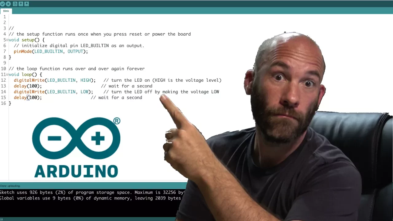
Arduino IDE Introduction
210.4K
The Arduino IDE is an integrated development environment used to write and upload code to Arduino boards, featuring essential tools like code verification, auto-formatting, serial monitoring, and serial plotting; key configurations include enabling line numbers and code folding in preferences, selecting the correct board type and COM port in the tools menu, and using the sketch menu to verify code, upload to the board, and include necessary libraries for advanced functionality.
Click to watch →

Basic concept of Arduino in Hindi | Arduino tutorials for beginners part #1
1.4M
Arduino IDE is free software available for all operating systems (Windows, Mac, Linux). Download from Arduino website by searching 'Arduino IDE' and clicking the first official option. After installation, the desktop icon launches the IDE containing: File menu (New, Open, Save), Examples menu with pre-written code templates (LED blinking, LCD interfacing, sensors), Sketch menu with Include Library for sensor commands, and Tools menu for board and port selection. For successful programming, select the correct board (Uno, Mega, Nano, Mini) and the connected serial port (e.g., COM3). The Upload button transfers programs to Arduino, enabling control of connected components like the built-in LED on pin 13.
Click to watch →
Deep Dive
Fundamental understanding of the SPI (Serial Peripheral Interface) communication protocol, including MOSI, MISO, SCK, and Chip Select (CS) lines.

Understanding SPI
221.2K
SPI is a four-wire serial communication protocol (developed by Motorola in the 1980s) used for transferring digital information between a master controller and one or more slave peripheral devices; it uses four wires—Chip Select (CS) for device selection, Serial Clock (SCLK) for timing, Master Out Slave In (MOSI) for data transmission from master to slave, and Master In Slave Out (MISO) for data reception from slave to master—with communication initiated by the master pulling CS low, and data sampled based on clock polarity (idle high or low) and clock phase (leading or trailing edge), which together define one of four SPI modes (0-3) that must match across all connected devices; multiple slaves can be connected either independently with separate CS lines or cooperatively in a daisy chain configuration.
Click to watch →
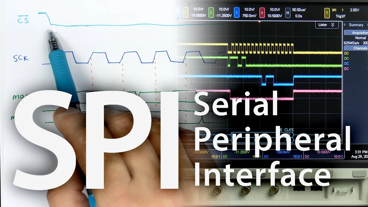
SPI: The serial peripheral interface
778K
SPI (Serial Peripheral Interface) is a communication protocol for connecting peripheral devices to microcontrollers. It uses a master-slave architecture where the controller (master) always initiates and controls communication. The interface requires four signals: Clock (generated by master), Chip Select (active low to enable devices), MOSI (Master Out Slave In for data from master to slave), and MISO (Master In Slave Out for data from slave to master). Multiple devices can share the same clock, MOSI, and MISO lines by using separate chip select signals.
Click to watch →

What is SPI? Basics for beginners!
170.5K
SPI (Serial Peripheral Interface) is a synchronous serial communication protocol used extensively in integrated circuits, appearing more frequently than USB (112,000 vs 49,000 products). It operates on a master-slave architecture where the master initiates all transactions. Four signal lines are required: SCLK (Serial Clock) provides synchronous timing; MOSI (Master Out Slave In) transmits data from master to slave; MISO (Master In Slave Out) receives data from slave to master; and SS/CS (Slave Select/Chip Select) enables communication with specific slaves using active-low signaling.
Click to watch →

SPI-интерфейс в разрезе и медленно • C • Live coding
1.6K
SPI (Serial Peripheral Interface) is a widely-used low-level communication protocol requiring 4-6 pins: MOSI (Master Out Slave In), MISO (Master In Slave Out), SCK (Serial Clock), and CS (Chip Select), plus power and ground. It enables full-duplex data transmission where data flows bidirectionally simultaneously over separate wires. The Serial Clock provides synchronization through clock pulses, telling devices when to sample and output data. The Chip Select signal activates specific devices on a shared bus, allowing multiple peripherals to connect to the same data lines. Without proper synchronization and device selection, communication fails as devices cannot coordinate data sampling and transmission.
Click to watch →

Raspberry Pi & Python SPI Deep Dive with TonyD! @adafruit LIVE!
19.6K
SPI (Serial Peripheral Interface) is a synchronous serial communication protocol for chip-to-chip communication. Unlike I2C which uses only two wires, SPI requires four lines: SCLK (clock), MOSI (master out slave in), MISO (master in slave out), and CS (chip select). Each device needs its own CS line because devices cannot share data lines without confusion. SPI offers much higher clock speeds (several MHz) compared to I2C's 400 kHz limit. The master controls the clock and manages chip select lines. SPI supports configurable polarity (CPOL) and phase (CPHA) settings that determine when data is sampled and whether the clock is active high or low, creating four SPI modes (0-3) that devices must match for proper communication.
Click to watch →
Deep Dive
Working principles of rotary encoders, specifically the difference between incremental and absolute magnetic encoders like the AS5048A.
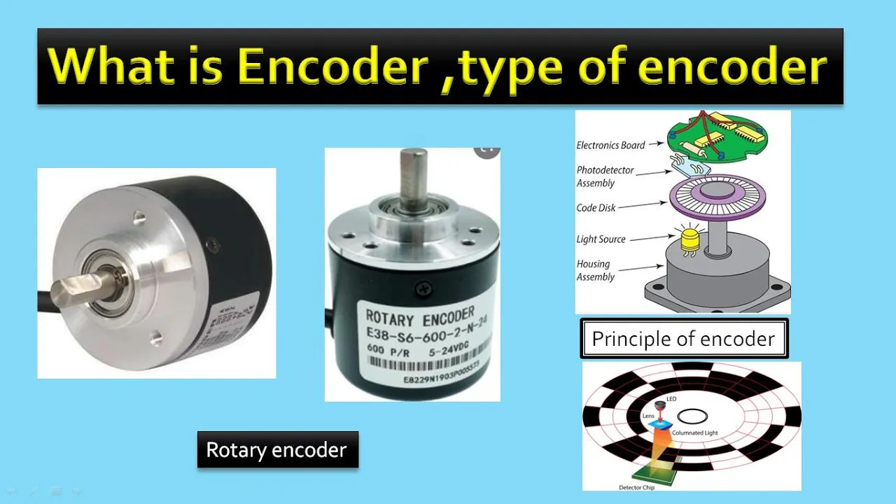
🔵what is encoder ? working principle and type of encoder. #linearencoder #incrementalencoder
28.7K
Rotary encoders measure rotational movement using a light source (LED), a rotary disk with alternating transparent and opaque sections, and a photodetector. Incremental encoders generate pulses based on disk rotation but lose position information when power is lost, requiring a home position reference. They use two channels with 90-degree phase difference for direction detection. Absolute encoders use unique concentric ring patterns read by multiple LEDs and phototransistors, generating binary-coded outputs that retain position information even after power loss. Each ring pattern creates a unique signal, and two channels with 90-degree phase difference determine rotation direction.
Click to watch →

Why the brushless controllers are awesome for robotics
145.2K
The AS5048A is a magnetic encoder that provides absolute position feedback using two communication methods: PWM signal output and SPI bus interface. When using PWM mode, the encoder outputs a pulse width proportional to the magnet position, which can be read through an analog input pin. When using SPI mode, the encoder communicates digitally through the SPI bus, requiring specific pin connections including MOSI, MISO, SCK, and CS (chip select) lines. Proper power connection (typically 3.3V) is essential for correct operation.
Click to watch →

difference between absolute encoder and incremental encoder
18.4K
Industrial automation uses two main encoder types: absolute and incremental. Absolute encoders provide unique position values for each position within a 360-degree range, resetting to zero after each full rotation. They output a specific number of pulses per revolution (typically 720-1440 PPR) and maintain position information without needing to count from a starting point. Incremental encoders generate pulses that accumulate continuously as the shaft rotates, requiring manual reset to establish a reference point. The key difference is that absolute encoders know their exact position at any time, while incremental encoders only track total movement since the last reset.
Click to watch →

Rotary Encoder Wiring/Connection with PLC II What is Rotary Encoder? (Autonics E40S6-2500-3-T24)
352.9K
A rotary encoder is a sensor that converts rotational motion into electrical signals, providing three critical measurements: exact position, rotation direction (clockwise/anticlockwise), and total rotation count. Industrial applications include motor feedback control in textile manufacturing, labeling machines, and cutting equipment. There are two main types: incremental encoders (relative position changes) and absolute encoders (unique position values). The working principle involves a rotating disk with slots interrupting light between transmitter and receiver, generating pulses proportional to rotation. Key parameters include Pulses Per Revolution (PPR) for resolution, and phase difference between output channels A and B for direction detection.
Click to watch →
EEVblog 1572 - Haefely 16kV ESD Tester TEARDOWN + Repair Part 1
46K
Rotary encoders come in two main types: incremental and absolute. Incremental encoders provide relative position information through directional signals (A and B channels that shift phase depending on rotation direction), allowing detection of movement but not absolute position. Absolute encoders provide unique codes for each position. The video describes an incremental encoder with two contacts per direction, which is typical for applications requiring simple directional tracking rather than precise position measurement.
Click to watch →
Deep Dive
The concept of sharing an SPI bus among multiple peripheral devices using dedicated Chip Select pins.
SPI: The serial peripheral interface
778K
Multiple SPI devices can share the same three signal lines (clock, MOSI, MISO) by using separate chip select signals for each device. When the master wants to communicate with a specific device, it pulls its corresponding chip select line low while keeping others high. This allows multiple devices to be connected to a single SPI bus, reducing the number of pins required on the microcontroller. A decoder chip like the 74LS138 can be used to expand a few control pins into multiple chip select signals.
Click to watch →

Serial Peripheral Interface (SPI) Basics
55.9K
The chip select (CS) line is an optional fourth wire in SPI that enables communication with multiple peripherals connected to the same bus. When the controller wants to communicate with a specific peripheral, it pulls the corresponding chip select line low (active low). Peripherals ignore communication when their chip select is high, allowing multiple devices to share the same SPI bus.
Click to watch →
I2C and SPI on a PCB Explained!
200.3K
SPI requires at least three pins: Master In Slave Out (MISO), Master Out Slave In (MOSI), and Serial Clock (SCK). Additional chip select (CS) pins are used to select which peripheral receives data. Each peripheral connects to all signal lines, and the CS pin determines which device is active. This allows multiple peripherals to share the same bus while being individually selectable.
Click to watch →

Don't Pick the Wrong OLED! I²C and SPI Explained for Arduino & ESP32
10.9K
Each SPI device has a chip select (CS) pin that determines which device receives data. When the microcontroller pulls a device's CS line low while keeping others high, only that device responds to the bus. After transfer completes, the master pulls CS high to end the session. This allows multiple SPI devices to share the same bus.
Click to watch →
EECS 373 - Fall 2025 - Lecture 12: "Serial Bus - SPI & I2C"
239
SPI uses a star topology where a single controller connects to multiple peripherals. Each peripheral requires its own dedicated chip select line, which the controller pulls low to select that specific device for communication. This means if you have N peripherals, you need N+1 chip select lines (one for each peripheral plus the common clock and data lines). The controller generates the clock and shifts data out on clock edges, while the peripheral shifts data back on the same clock edges.
Click to watch →
Prerequisite Knowledge
- Concept 01Basic proficiency with the Arduino IDE, writing sketches, and digital I/O pin configuration.
- Concept 02Fundamental understanding of the SPI (Serial Peripheral Interface) communication protocol, including MOSI, MISO, SCK, and Chip Select (CS) lines.
- Concept 03Working principles of rotary encoders, specifically the difference between incremental and absolute magnetic encoders like the AS5048A.
- Concept 04The concept of sharing an SPI bus among multiple peripheral devices using dedicated Chip Select pins.
Subsequent Learning
- Step 01Implementing PID closed-loop control systems using the encoder feedback to control DC or stepper motors.
- Step 02Optimizing SPI read speeds using hardware interrupts, non-blocking code, or Direct Memory Access (DMA) on 32-bit microcontrollers (e.g., ESP32, STM32).
- Step 03Applying dual-encoder feedback to robotic joints or gimbal systems to calculate precise angular orientation and forward kinematics.
- Step 04Developing digital filtering techniques, such as Kalman or low-pass filters, to mitigate sensor noise in high-speed rotary applications.
SPI wiring
Code logic
Live test
SPI wiring
0:00Playing Section
- 1
Connects two magnetic encoders via SPI to Arduino Uno.
- 2
Shares MISO and clock on pins 12 and 13.
- 3
Uses A0 and A1 for individual chip enable.
Limitations of 8-Bit MCUs and SPI Polling for High-Performance Motion Control
While connecting dual AS5048A encoders to an Arduino Uno via SPI is an excellent educational exercise, it introduces severe bottlenecks for real-time, high-performance motion control applications like robotics. The 8-bit ATmega328P processor lacks Direct Memory Access (DMA) and operates at a modest 16 MHz. Consequently, retrieving 14-bit data from multiple SPI devices requires CPU-intensive polling that can starve critical tasks like PID calculations or motor commutation. An alternative, more robust architecture involves upgrading to 32-bit microcontrollers (such as STM32 or ESP32) that support DMA-driven SPI transfers, allowing encoder data to be retrieved in the background without CPU overhead. Furthermore, in industrial or high-noise environments, developers often reject standard single-ended SPI due to its susceptibility to electromagnetic interference (EMI) from motors. Instead, they opt for differential signaling protocols like BiSS-C or SSI, or utilize the encoder's hardware quadrature (ABI) outputs to offload tracking to dedicated hardware timer counters.
Deep Dive
Implementing PID closed-loop control systems using the encoder feedback to control DC or stepper motors.
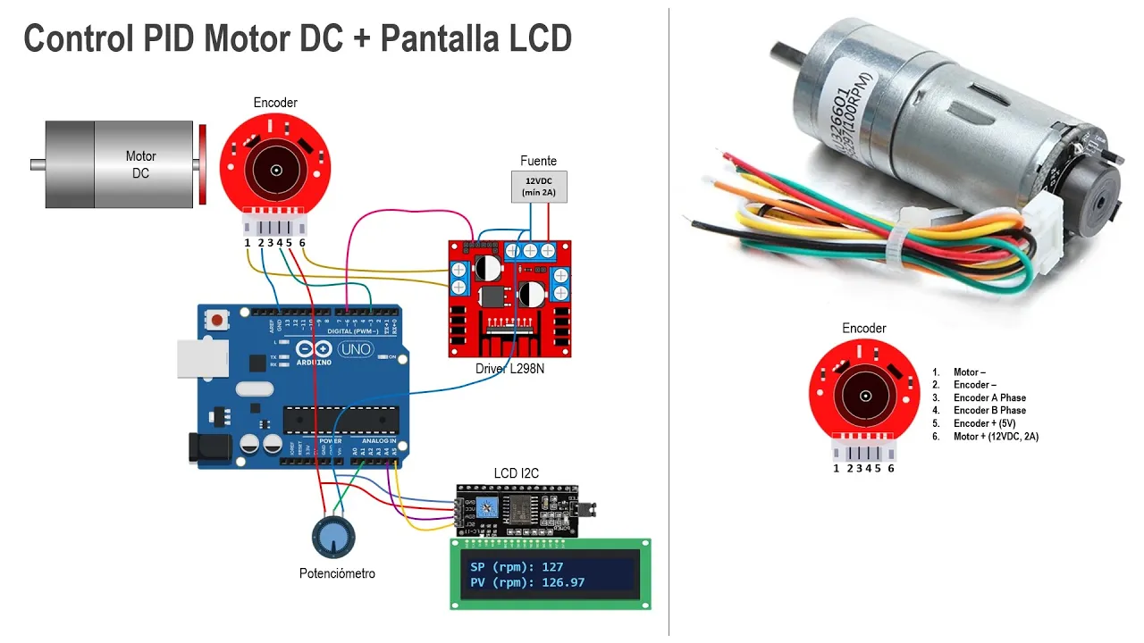
Control PID para Motor DC con encoder - Arduino
229.6K
This video demonstrates how to implement a PID (Proportional-Integral-Derivative) controller for speed control of a DC motor equipped with an encoder using Arduino. The process involves three main stages: first reading encoder pulses to measure motor speed by counting rising edges on a digital pin using interrupts; second calculating RPM from pulse counts by applying the formula RPM = (pulses_per_second × 60) / (encoder_resolution × gear_reduction_ratio); and third implementing the PID algorithm using the difference equation derived from the continuous-time PID transfer function, where the output is calculated as u(k) = Kp×error(k) + Ki×Ts/2×(error(k)+error(k-1)) + Kd×(error(k)-error(k-2))/Ts, with error(k) being the difference between setpoint and measured process variable. The final implementation includes an LCD display for real-time monitoring of setpoint and actual RPM values.
Click to watch →
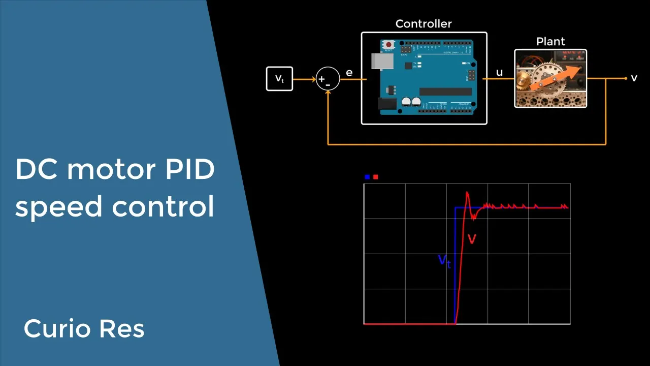
DC motor PID speed control
313.9K
This video demonstrates how to implement precise DC motor speed control using a PID controller with encoder feedback. The process involves measuring motor velocity through a magnetic encoder, applying a low-pass filter to smooth measurements, and implementing a PI (Proportional-Integral) controller to maintain target speed despite loading variations. The key steps include: (1) Hardware setup with motor driver and encoder; (2) Velocity measurement using encoder signals; (3) Filtering raw encoder data with a low-pass filter; (4) Implementing proportional control to reduce error; (5) Adding integral control to eliminate steady-state error; (6) Tuning controller parameters (Kp and Ki) for stable response. The video shows that while proportional control alone can track speed, it leaves steady-state error, which the integral term eliminates. However, improper parameter tuning can cause overshoot and oscillation. The low-pass filter is essential for reducing high-frequency noise from discrete encoder measurements, especially important at low speeds where quantization effects become more pronounced.
Click to watch →
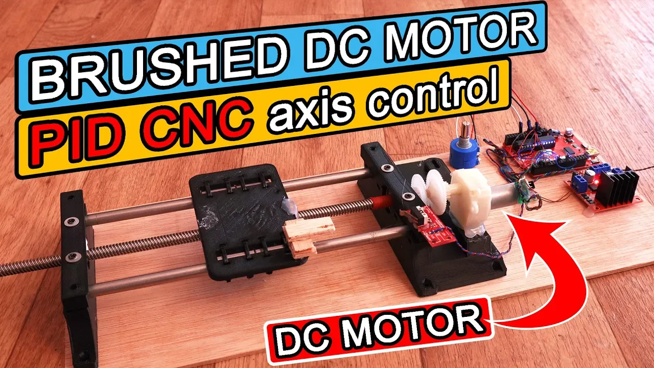
One axis PID encoded DC motor control
173K
This video demonstrates how to implement a closed-loop control system for a DC brushed motor using PID control with an encoder for feedback. It details the necessary components including an Arduino, a DC motor with integrated encoder, an H-bridge for motor driving, a potentiometer for setpoint input, smooth rods, a lead screw, linear bearings, and a limit switch for mechanical positioning. The tutorial covers the physical wiring connections between these components and provides access to the complete schematic, part list, and Arduino code for PID implementation via linked resources. The system uses the encoder to measure actual motor position and compares it to a desired setpoint (input via potentiometer), adjusting motor output through PID algorithm to minimize error. The video emphasizes practical implementation, including mechanical assembly using 3D-printed parts available for download. The tutorial is structured to guide viewers through building a precise linear motion system where motor position is accurately controlled in real time. All code, schematics, and 3D files are provided as downloadable links for replication. The focus is on applying PID control fundamentals to real-world motor positioning tasks using affordable, accessible hardware.
Click to watch →

Stepper motor PID control using a TMC2209 and AS5600
26.9K
This video demonstrates how to implement a rudimentary PID (Proportional-Integral-Derivative) control algorithm for stepper motors using a TMC2209 stepper motor driver and an AS5600 magnetic encoder. The system uses the AS5600 absolute encoder to provide position feedback, allowing the PID controller to continuously calculate the error between the target position and the actual motor position. The control signal generated by the PID algorithm drives the TMC2209 driver to move the stepper motor, enabling precise position tracking and automatic correction when external forces attempt to rotate the motor shaft. The demonstration shows the motor returning to its target position after being manually displaced, illustrating the closed-loop control capability of this setup.
Click to watch →

The Ultimate Guide to using Motors in Robotics (including ROS, Raspberry Pi)
483.9K
Implementing closed loop control requires encoder integration and empirical calibration. Encoders use hall effect sensors that generate pulses as a magnetic disk rotates. By counting pulses and dividing by rotation count, we determine counts per revolution (e.g., 3,450 counts/rev). The controller uses PID algorithms to compare actual vs target speeds, adjusting PWM outputs accordingly. Commands like 'm' followed by target counts per loop enable closed loop operation. This demonstrates transforming theoretical feedback control concepts into working hardware implementations.
Click to watch →
Deep Dive
Optimizing SPI read speeds using hardware interrupts, non-blocking code, or Direct Memory Access (DMA) on 32-bit microcontrollers (e.g., ESP32, STM32).

Using DMA to implement multiple SPI ports
31.9K
This video demonstrates how to use Direct Memory Access (DMA) to implement multiple SPI ports on a PIC32 microcontroller for driving LED strips. The technique involves using a timer to generate DMA transfers that output data to parallel ports, with a secondary DMA task stopping the timer when complete. This approach eliminates the interrupt overhead that limits traditional interrupt-driven methods to around 100 kHz, enabling operation at 500 kHz SBI clock rates. The solution uses a single chip with no external gating, making it simple, low-cost, and easy to debug.
Click to watch →
Mastering SPI Interrupts in STM32 | Non-Blocking Communication with MCP2515 Example
411
This video demonstrates how to implement non-blocking SPI communication using interrupts on STM32 microcontrollers, where an external interrupt (from a button press) triggers an SPI read operation to fetch device status from an MCP2515 CAN controller module. The implementation uses HAL_SPI_TransmitReceive_IT() for concurrent data transmission and reception, with completion callbacks handling CS pin management and data processing, enabling efficient, responsive embedded systems that don't block the main program execution while waiting for peripheral responses.
Click to watch →

Подключение дисплея ST7789 к микроконтроллеру STM32 по SPI c DMA без HAL: явное преимущество DMA
16.2K
Using DMA (Direct Memory Access) for SPI communication with an ST7789 display on STM32 microcontroller significantly improves performance by enabling parallel processing, where the microcontroller core continues executing code while DMA handles data transfer, resulting in approximately 47 frames per second compared to 43 fps without DMA, and maintaining 32 fps even under CPU load versus 31 fps without DMA.
Click to watch →

Getting Started with STM32 and Nucleo Part 5: How to Use SPI | Digi-Key Electronics
171K
SPI (Serial Peripheral Interface) is a synchronous serial communication protocol developed by Motorola that enables full-duplex data transfer between a master controller and multiple peripheral devices using four signal lines: SCLK (clock), MOSI (master out slave in), MISO (master in slave out), and CS (chip select). The protocol operates in four modes determined by clock polarity (CPOL) and phase (CPHA) parameters, with Mode 0 (CPOL=0, CPHA=0) being the most commonly used configuration where the clock idles low and data is sampled on the rising edge. In this tutorial, we demonstrate SPI implementation on an STM32 Nucleo board using STM32CubeIDE and the HAL library, including both blocking and interrupt-driven approaches for reading from and writing to an external EEPROM chip, showing how to configure the SPI peripheral, manage chip select lines, and implement non-blocking communication for efficient real-time applications.
Click to watch →
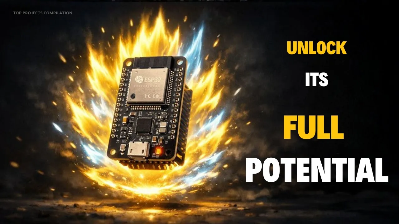
10 ESP32 Pro Features: Take your Projects to the Next Level!
181.4K
DMA (Direct Memory Access) allows the ESP32 to transfer large amounts of data directly between memory and peripherals without involving the main CPU. This feature, typically found in more powerful processors, enables smooth animations on TFT displays, audio playback through I2S, and high-speed sensor operation without blocking the main code. With DMA handling heavy data transfer tasks, the main cores remain almost completely free for other operations.
Click to watch →
Deep Dive
Applying dual-encoder feedback to robotic joints or gimbal systems to calculate precise angular orientation and forward kinematics.
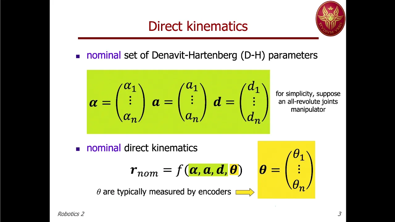
Robotics 2 - Prof. De Luca Lecture 02 (26 Feb 2020)
4.2K
Encoder mounting errors (constant angular bias in joint angle measurements) have the largest effect on positioning accuracy. A two-stage calibration strategy addresses this: First, estimate only the encoder bias parameters (Delta theta) while assuming nominal DH parameters are correct. This removes the dominant error source. Second, restart the full calibration problem with the corrected encoder biases, allowing variations in all parameters. This conditioning improves numerical stability because all parameter variations now have comparable expected amplitudes.
Click to watch →

Denavit - Hartenberg (DH) Tables For Robotic Systems - Direct Kinematics II
231.9K
The Denavit-Hartenberg (DH) representation is a systematic method for describing the position and orientation of robotic joints using four parameters: a_i-1 (link length, distance between joint axes along the common perpendicular), alpha_i-1 (link twist, angle between joint axes about the common perpendicular), d_i (link offset, distance between origins along the previous joint axis), and theta_i (joint angle, rotation about the current joint axis). For prismatic joints, d_i is non-zero while theta_i is zero; for revolute joints, theta_i is non-zero while d_i is zero. These four parameters are organized into a DH table, which enables the calculation of transformation matrices that describe the spatial relationship between consecutive frames in a robotic manipulator.
Click to watch →

Inverse Kinematics of a 6-DoF Industrial Robot (Yaskawa GP12)
12.6K
After determining theta1, theta2, and theta3 from wrist center position, perform forward kinematics to compute transformation matrix 0T3 (from base to wrist center). This matrix contains rotation part 0R3. The rotation matrix from wrist center to end effector (3R6) is found by multiplying 0R6 (known from orientation input) by the transpose of 0R3 (since 0R3 × 3R6 = 0R6). This provides the orientation relationship needed for solving remaining joint angles.
Click to watch →

Robotics Project Inverted Pendulum P2: Encoder for angular position/velocity. STM32 Timer Encoder
1K
Angular position in radians is calculated by scaling the timer counter value using the encoder resolution. Angular velocity is obtained by computing the difference between consecutive angle measurements. Special handling is required during rotation transitions to handle counter wrap-around correctly. Real-time monitoring involves initializing the encoder, reading the timer counter periodically, calculating position and velocity, and optionally plotting results. This feedback system enables precise control applications like inverted pendulum stabilization.
Click to watch →
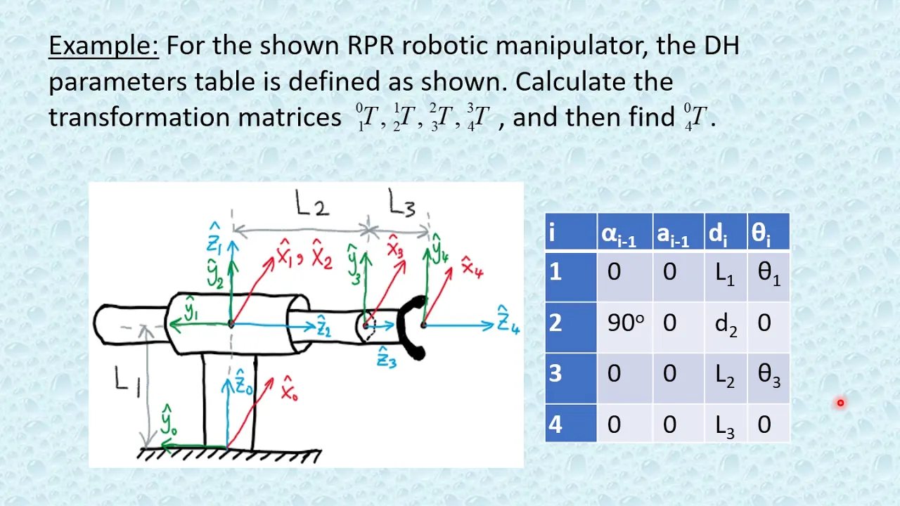
Ch3 Part 3
18.4K
This segment demonstrates applying forward kinematics to an RPR (Revolute-Prismatic-Revolute) manipulator. The DH parameters table provides values for each link-joint pair. For each transformation matrix Tᵢ₋₁ᵢ, substitute the corresponding DH parameters into the general equation. When alpha or a equals zero, those transformations become identity matrices and can be omitted. The final composite transformation matrix T₀₄ contains three variables (θ₁, d₂, θ₃) representing the three degrees of freedom. Substituting specific joint values allows calculation of the end effector's position and orientation in space.
Click to watch →
Deep Dive
Developing digital filtering techniques, such as Kalman or low-pass filters, to mitigate sensor noise in high-speed rotary applications.

การใช้งาน Digital Filter กับ MPU6050 ด้วย Arduino
2.1K
This segment covers the complete process of designing a digital low-pass filter to reduce noise in MPU6050 sensor data. The video demonstrates how raw sensor readings become unstable when the device is shaken, and explains the mathematical foundation using the transfer function G(s) = 1/(τs + 1), where τ = 1/(2πfc). For a 1 Hz cutoff frequency, τ ≈ 0.159 seconds. The instructor shows how to implement this in MATLAB using tf() and c2d() functions, converting the continuous-time filter to discrete-time for digital implementation. This provides a complete theoretical and practical foundation for understanding digital filtering in embedded systems.
Click to watch →

Lowpass filters explained - deep basics
6.1K
Flight controllers receive noisy sensor readings from gyroscope chips due to electrical interference, motor vibrations, and inherent sensor imperfections. Directly using raw measurements causes motors to react to useless garbage data, potentially burning out motors. The process of smoothing noisy data and estimating actual values is called filtering. A PT1 filter balances between trusting new measurements (Dig) and trusting previous filtered values (Bill). With 50/50 trust levels, the filter outputs the average of new and old values. The formula is: new_filter_value = previous_filtered_value × Bill_trust + new_measurement × Dig_trust. Higher Dig coefficients mean more trust in new values (lower latency but more noise), while lower Dig coefficients mean more trust in conservative estimates (smoother signal but higher delay).
Click to watch →

Kalman Filtering, how it works and how it compares to Betaflight's dynamic PT1 lowpass filters
7K
A Kalman filter is an optimal estimator that combines predictions from a system model with sensor measurements to produce more accurate state estimates than either source alone, using a two-step process where the prediction step forecasts future states and calculates uncertainty, while the update step combines predictions with measurements based on their relative uncertainties using a Kalman gain matrix; unlike static low-pass filters, Kalman filters dynamically adjust their filtering characteristics based on the relationship between prediction accuracy and measurement reliability, making them particularly effective for RC quadcopters where they can filter sensor noise while preserving dynamic response during maneuvers.
Click to watch →

Sensor Filtering in FRC
860
This comprehensive section covers the complete fundamentals of sensor filtering for robot control in FRC. It begins with the importance of sensor filtering for precise robot control, introduces various sensor types (encoders, potentiometers, cameras, IMUs), and explains how optical encoders work by counting transitions on a spinning disc. The section addresses sensor imperfections, including the inability to determine exact position between transitions and the calculation of velocity from position changes, which produces jagged, noisy data. It covers approaches to handling sensor data: ignoring data for low-precision applications, buying better sensors, building stiffer mechanisms, making mechanisms self-centering, improving wiring, and using filtering to remove high-frequency noise. The section emphasizes using prior knowledge about motors, mass, and gear ratios to improve estimates. It then transitions to the Kalman filter, explaining Gaussian noise characteristics, covariance matrices, and the filter matrices (F, H, Q, R). The section details the prediction and measurement update steps, explaining how the Kalman gain determines how much to trust the sensor versus the model based on current uncertainty and sensor noise characteristics.
Click to watch →

MATLAB Arduino Tutorial 4 - Filtering Noise out of 3-axis Accelerometer Data in Real-time
42.8K
This tutorial covers two fundamental digital filtering techniques for removing noise from accelerometer sensor data. The Exponential Moving Average (EMA) filter applies recursive weighting using an Alpha coefficient (0-1), where higher Alpha values reduce filtering strength. The Simple Moving Average (SMA) filter calculates the arithmetic mean of a fixed number of recent readings (window size or taps). Both filters attenuate high-frequency noise while preserving low-frequency signal components. The choice between filter types depends on the application requirements: EMA offers computational efficiency with adjustable filtering strength, while SMA provides straightforward averaging with predictable frequency response characteristics.
Click to watch →
SPI wiring
Code logic
Live test
SPI wiring
0:00- 1
Connects two magnetic encoders via SPI to Arduino Uno.
- 2
Shares MISO and clock on pins 12 and 13.
- 3
Uses A0 and A1 for individual chip enable.
Limitations of 8-Bit MCUs and SPI Polling for High-Performance Motion Control
While connecting dual AS5048A encoders to an Arduino Uno via SPI is an excellent educational exercise, it introduces severe bottlenecks for real-time, high-performance motion control applications like robotics. The 8-bit ATmega328P processor lacks Direct Memory Access (DMA) and operates at a modest 16 MHz. Consequently, retrieving 14-bit data from multiple SPI devices requires CPU-intensive polling that can starve critical tasks like PID calculations or motor commutation. An alternative, more robust architecture involves upgrading to 32-bit microcontrollers (such as STM32 or ESP32) that support DMA-driven SPI transfers, allowing encoder data to be retrieved in the background without CPU overhead. Furthermore, in industrial or high-noise environments, developers often reject standard single-ended SPI due to its susceptibility to electromagnetic interference (EMI) from motors. Instead, they opt for differential signaling protocols like BiSS-C or SSI, or utilize the encoder's hardware quadrature (ABI) outputs to offload tracking to dedicated hardware timer counters.
Basic proficiency with the Arduino IDE, writing sketches, and digital I/O pin configuration.
Fundamental understanding of the SPI (Serial Peripheral Interface) communication protocol, including MOSI, MISO, SCK, and Chip Select (CS) lines.
Working principles of rotary encoders, specifically the difference between incremental and absolute magnetic encoders like the AS5048A.
The concept of sharing an SPI bus among multiple peripheral devices using dedicated Chip Select pins.
Implementing PID closed-loop control systems using the encoder feedback to control DC or stepper motors.
Optimizing SPI read speeds using hardware interrupts, non-blocking code, or Direct Memory Access (DMA) on 32-bit microcontrollers (e.g., ESP32, STM32).
Applying dual-encoder feedback to robotic joints or gimbal systems to calculate precise angular orientation and forward kinematics.
Developing digital filtering techniques, such as Kalman or low-pass filters, to mitigate sensor noise in high-speed rotary applications.
2.8K views34likes4:39@mailo66Original Release: 2022-11-27
here we have the setup with two electric motors A and B connected to two magnetic encoders type as50 48a but here I want to show the connections of these two encoders both together to the Arduino Uno board and they are functioning as for the connections here we have the connections according to SPI protocol that is showed in this this scheme in which we have to connect the two miles and the two clocks pins of the uh magnetic encoders to the 12th and 13 pins of Arduino here we have the yellow is the 12th and the red is the 13 pins of Arduino and they are connected to everyone to both the corresponding miso and clock of the two encoders then we have of course the connections to the power supply ground and plus five volt of Arduino is connected to mausi here these two are the ground and mausi ground MRC of the encoder on the on the left and this is the ground embody of the encoder on the right this is a and they take the power supply from these two connectors to the pins from Arduino and here and here we have the two chip select a0 and A1 the right encoder is connected to the eight zero and the left is connected to the A1 as for the code the code is very simple this is the code here we have the definition of the two select pins what do we know h0 and A1 here the definitions of the clock and myizo and so on and we have the loop in which it is called the written code the written codex subroutine which is in the in the last part of the software here so here there is a sequence of the core of both the encoder and and subroutine works [Music] reading two bytes one at a time and then composing the two bytes and then there is in power sank is stored the actual position of the cold encoder which is a return to post R and plus b uh here there is a mapping of the position of between the 6 384 which are the position of a 14 bit 2 0 3 5 9 degrees 59 degrees okay so let's go let's see how it works I connect and now I upload the code on they are doing now and now we can see the functioning on the serial protests here we can see that the we have a b encoder and the app encoder that works works well same direction [Music] opposite direction so the functioning is very good it is SPI protocol connecting the both encoder to the the same bars of the SPI protocol
Up Next

11:38
Moza R5 Bundle Review: Entry-Level Direct Drive Wheelbase Analysis
@napmanreviews
5.8K views•2023-07-17

12:54
Triumph of Orthodoxy Icon: Byzantine Art & History Explained
@BenCallan
2.1K views•2024-08-06

9:49
FastAPI vs Flask vs Django: Choosing the Right Python Web Framework
@TechWithTim
302.5K views•2024-05-26

1:42
Game of Thrones Opening Credits: A Cinematic Analysis
@gameofthrones
46.3M views•2011-04-18
Related Study Plans & Knowledge Roadmaps
Structured learning paths in General & Interdisciplinary Studies
general-studies
Elevator Engineering: History, Physics & Cities
01From Hoists to Safety Brakes: The Dawn of Vertical Lift
02Hydraulic vs. Traction: The Engineering Physics of Elevators
03Modern Speed, Safety, and Algorithms
+ 2 more learning modules
12h5 modules
Explore Roadmap
general-studies
Rubber: Material Science, History & Geopolitics
01Origins of Natural Rubber & Mesoamerican History
02The Chemistry of Natural Rubber & Vulcanization
03The Geopolitics of the Rubber Boom & Colonization
+ 2 more learning modules
12h5 modules
Explore Roadmap
general-studies
Containerization: Evolution, Logistics & Trade
01Ancient Trade & Bulk Cargo: Amphorae to Barrels
02The Industrial Revolution & Cardboard Packaging
03The Containerization Revolution: Malcom McLean
+ 2 more learning modules
12h5 modules
Explore Roadmap
general-studies
Textile Tech: Evolution, Labor & Global Impact
01Pre-Industrial Textiles: Handloom & Cottage Industry
02Mechanization: The Spinning Jenny to the Power Loom
03The Factory System & Global Labor Transformation
+ 2 more learning modules
10h5 modules
Explore Roadmap