

![14 - Structural Dynamics - Single Degree of Freedom System and Equation of Motion [Urdu Language]](https://i.ytimg.com/vi/z6oF7H105As/maxresdefault.jpg)















![Come proteggere un edificio dal sisma, senza toccare la struttura - Ep. 14 [Brain Hunter Podcast]](https://i.ytimg.com/vi/Fbh_p8crjHw/sddefault.jpg)







A Tuned Mass Damper (TMD) is a passive vibration control device consisting of a mass, spring, and damper that reduces structural vibrations by tuning its natural frequency to match the primary structure's frequency, thereby creating out-of-phase motion that dissipates vibrational energy; the optimal design parameters include a mass ratio of 5-10% of the main structure, with optimum damping ratio and frequency ratio determined by the mass ratio and system characteristics to minimize displacement amplitudes under harmonic excitation.
Tuned Mass Damper Design: Structural Dynamics Explained
Added:Fundamentals of Single-Degree-of-Freedom (SDOF) systems, including mass, stiffness, and damping concepts.
The concept of resonance, natural frequency, and how structures respond to dynamic harmonic excitation.
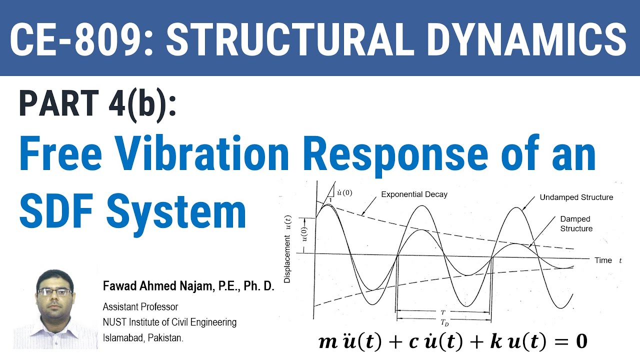
Basic differential equations of motion governing structural dynamics and mechanical vibrations.
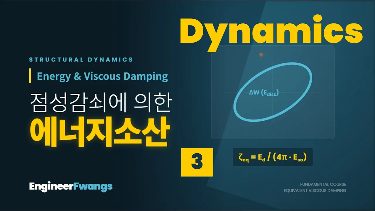
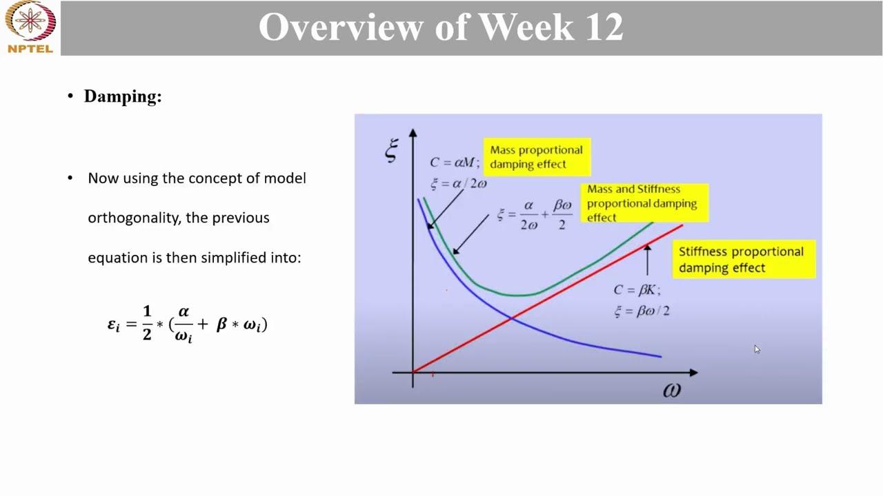
Understanding the damping ratio and its role in energy dissipation in vibrating systems.
Design and analysis of Tuned Mass Dampers in Multi-Degree-of-Freedom (MDOF) systems, such as multi-story buildings.
Advanced structural control strategies, including Active Mass Dampers (AMDs) and semi-active control systems.
Alternative passive energy dissipation technologies, such as Tuned Liquid Column Dampers (TLCDs) and base isolation systems.
Real-world engineering applications and case studies of TMDs, such as those used in Taipei 101 or long-span bridges under wind loading.
31.7K views371likes10:55Original Release: 2016-10-02
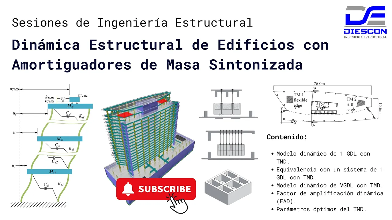
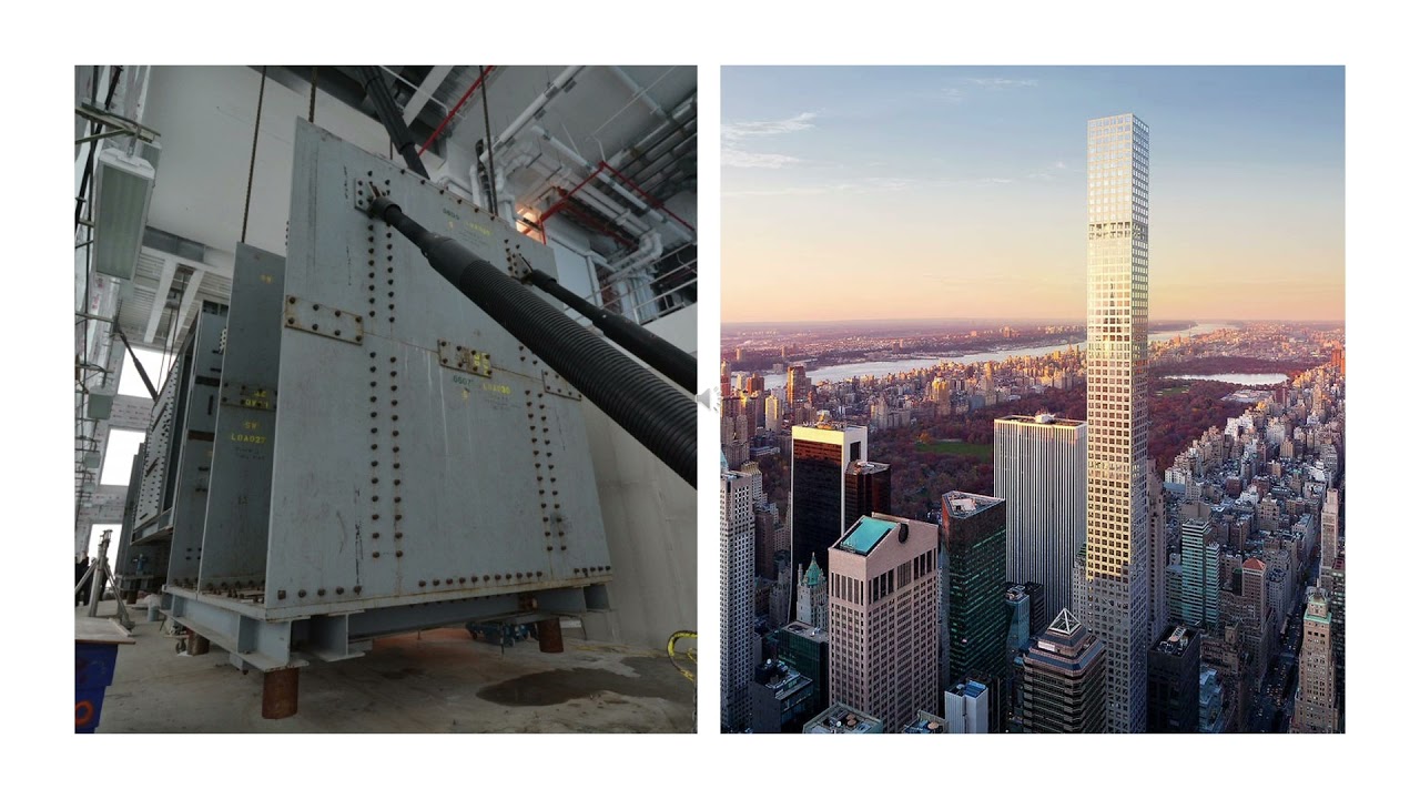
[Music] welcome to structural Dynamics class so in this class we will study about tuned Mass damper so what is tuned Mass damper so tune Mass damper is controlling the vibration of a structure are uh by using mass so the tuning is done according to the frequencies so there is a structure and this structure the primary structure so this has uh severe vibrations because of some uh given input so when vibration amplitude is more so there will be uh safety issues to the occupants and comfort issues to the occupants so what we need to do is we need to control the vibration so tuned Mass damper is tuning the frequency of the secondary structure which we are going to install uh either on the top or anywhere in this structure and the frequency of that structure matching with the frequency of the primary structure and using this two we will derive the damping which is which needs to be present in the secondary structure uh because the damping already present in the primary structure is insufficient to control the vibration so this this is the main concept of tuned Mass damper so a tuned Mass damper or popularly called as TMD is a device consisting of a mass a spring and a damper that is attached to a structure in order to reduce the dynamic response of the structure so the frequency of the damper is tuned to a particular structural frequency so that when that frequency is excited the damper will resonate out of face with the structural motion so let's look at this structure this is type 101 Building and on top tune Mass damper is installed so if you look at closely it looks like this so this is a mass system hanging from this location so in the form of pendulum so this makes the severe vibration out of phase so that the total vibration or the maximum displacement will reduce so as you can see this is the motion animation of it you can clearly see that so in Long span Bridges also it is done so this is a exaggerated cartoon so showing how the uh dampers are installed now let us look at formulation part in this formulation you can see uh this is a primary structure on which a second secondary structure is constructed for explanation of concept I have kept one additional floor but it is not needed it can be a very very small component which is having some percentage of uh weight of the building so that weight can be 5% to 10% the weight of the building so this is called main structure and this is tune Mass damper and as you can see this tune Mass damper acts like this so this is a conceptual uh uh explanation so this is primary structure secondary structure so this secondary structures uh weight or mass can be from 5% to 10% okay in some cases it is even less so in this one uh primary structures stiffness primary structures damping so this is approximately zero it's not present are very less value so this value we have to find out and uh mass and uh stiffness together will offer Omega D that is uh frequency natur damped natural frequency of this system and these two offer natural frequency of the primary system so tuning is done between primary structures frequency and the secondary structures frequency so mass of main structure m c damping of main structure K is a stiffness of main structure MD is mass of damper CD is damping of damper KD is stiffness of damper and U is the displacement and UD is the displacement of the damper now now if we formulate the two degree of Freedom uh system uh Mass Matrix so this is actually this m is n degree of Freedom system already this is n degree of Freedom system it is there and the additional damper system is adding one more degree of Freedom system so M 0 0 MD U Dot and U uh D do D C+ CD minus CD minus CD CD U dot velocity of uh primary system velocity of damper k + KD minus KD minus KD and KD U and UD U is the displacement of primary system and then UD is the displacement of damper so m uou dot is is a force acting due to earthquake ground motion MD into U dot is Fort acting on the damper due to earthquake ground motion so the total equation of motion is Mu do+ CU do+ KU is equal to minus m u do G so where m is Matha matx compound Mass Matrix C is damping Matrix compound damping Matrix K is compound stiffness Matrix U dot is acceleration vector velocity vector and displacement Vector is used when the support excitation is harmonic its displacement amplitude is fixed and independent of input frequencies that is U is equal to h e to the^ of I Omega T so this is assumed displacement profile this is in steady state response if we take the displacement response that is a into U Vector is equal to the response Vector so as you can see Omega is a natural frequency gamma Omega D Omega a i 2 Omega a all this uh complex notations where Omega is natural frequency of the primary system Omega D is KD by MD so natural frequency of the uh damper and Zeta value is damping C by 2 m Omega and Zeta d is this is Zeta present in the primary structure this is damping present in the damper and Gamma is a mass ratio so MD by m so mass of the damper by damper so now you know all these values if we plug in this we'll get the ratio of displacement amplitude of the main Mass to the input amplitude can be solved so this is displacement of the main mass and this is input amplitude so is this complex where frequency ratio is Omega d by Omega and G is Omega a by Omega so Optimum parameters for undamped system are harmonic main Mass excitation so F Optimum is 1 by 1 + gamma so gamma is a mass ratio so Zeta damping so damping of the damper Optimum is 3 gamma by 8 into 1 + gamma under root harmonic base excitation so F Optimum and uh Zeta Optimum values are given so for Optimum parameters for damped systems F Optimum is given and Zeta Optimum is given like this so let's solve an example problem using these complex notations so a single story single base structure with plan Dimension 7 m by 7 m and taken and a tuned Mass damper is designed for no damping condition so that means what when primary structure has no damping present in it so we want to damp the reduce the vibration energy or vibration amplitude by using tuning of second uh Mass so cross-section of beams columns uh thickness of slab concrete grid is given so it is a this is a structure uh figure of the structure and then let us calculate modulus of velocity that is known as five given in is 456 that is 5,000 under root fck so we know this value and then uh moment of inertia along X Direction and along y direction so because it is symmetric in both directions so this Mi is same in both directions and then calculation of the mass so we take weight of the slab weight of column weight of beam and total mass so 27,600 kg and then natural frequency of primary system so 74.1 5 radians per second so that offers 8 Seconds then assume Mass ratio as 03 so that means 3% mass is taken so mass of the uh secondary structure of damper is 828 kg the stickness of the damper is again 3% is taken this one just we need to tune it now because we need to match the frequency that's why same ratio is used in mass as well as in stiffness so F Optimum is 1x 1 + gamma that is mass ratio so 978 and uh Zeta d that is damper Optimum damping value is taken as say 0.1 so that will become uh 10% of damping so stiffness Optimum damping Optimum if we calculate so we get these values and then so these values when we adopt and apply in the uh that compound uh Mass Matrix stiffness Matrix uh we get the uh final response as a reduced response so damping in the secondary system is helping primary system in two ways number one it is changing the phase of the primary system that means frequency because of the frequency uh of the compound system is different from frequency of primary system IF frequency of primary system and excitation frequency matches then it will go into resonating condition and uh amplitudes will become high so because of the presence of the secondary system so frequency is changed so that your frequency ratio compared to compound uh structure and excitation frequency is now either less than the original frequency ratio or more than the original frequency ratio in both the cases vibration amplitude reduces severely so uh in summary so we have studied how to design a tuned Mass damper in this class [Music]
Up Next

33:39
How a Student's Question Saved a NYC Skyscraper from Collapse
@veritasium
22.8M views•2025-04-26

30:32
Ultrasonic Transducers: Resonant Frequency Measurement and Horn Design
@imajeenyus42
229.9K views•2017-02-22

54:16
Polymer Environmental Degradation: Mechanisms & Stabilization
@iit
1.8K views•2012-07-10

55:00
The Advanced Engineering Behind ASML's EUV Lithography Machines
@veritasium
18.2M views•2025-12-31
Related Study Plans & Knowledge Roadmaps
Structured learning paths in Engineering
engineering
Building Acoustic Levitators: Physics & Arduino
01The Physics of Sound and Standing Waves
02Piezoelectric Transducers and H-Bridge Drivers
03Arduino Programming: Generating 40 kHz Signals
+ 2 more learning modules
14h5 modules
Explore Roadmap
engineering
Building Peltier Cloud Chambers: Particle Tracks
01Cosmic Rays & Cloud Chamber Physics
02Thermoelectric Cooling (TEC) Fundamentals
03Custom Liquid-Cooling Loop Design
+ 2 more learning modules
18h5 modules
Explore Roadmap
engineering
Yagi-Uda Antennas: Modeling, Build & VNA Test
01Introduction to RF and Antenna Fundamentals
02Yagi-Uda Antenna Design Principles
03Antenna Modeling and Simulation in 4NEC2
+ 2 more learning modules
18h5 modules
Explore Roadmap
engineering
ECG Monitor Design: Op-Amps, Filters & Noise
01Electronics & Breadboard Basics
02Op-Amps and Instrumentation Amplifiers
03Bioelectricity and ECG Fundamentals
+ 2 more learning modules
18h5 modules
Explore Roadmap