This video demonstrates the complete process of setting up and programming an STM32F103 microcontroller for a fly controller application, including hardware connections with jumpers, establishing debugger connections, configuring communication protocols, and verifying successful device communication through practical demonstration.
How to Flash STM32F103-Based Flight Controllers with ST-Link
Added:Deep Dive
Basic understanding of microcontroller architecture, specifically the ARM Cortex-M3 processor used in the STM32F103 series.

STM32F1 'e Girişi, Temel Mimarisi
4.4K
ARM (Advanced RISC Machine) is a processor architecture designed by ARM Ltd., founded in 1990, headquartered in England. ARM uses a reduced instruction set computer (RISC) architecture, characterized by low power consumption and high performance. The Cortex-M series represents ARM's microcontroller line with performance tiers: M0 (entry-level), M0+ (improved energy efficiency), M3 (balanced performance), M4 (DSP capabilities), and M7 (highest performance). ARM licenses its architecture to manufacturers like STMicroelectronics, NXP, and Texas Instruments. The Cortex-M bus architecture consists of AHB (Advanced High-performance Bus), D-Bus, and S-Bus, with the bus matrix using round-robin arbitration. The AHB bridge connects to APB1 (up to 36 MHz) and APB2 (up to 72 MHz) buses. Memory organization provides a unified 4GB address space (32-bit addressing) divided into 8 blocks of 512 MB each. STMicroelectronics produces STM32 series devices organized into performance tiers: High Performance (F4, F2) using Cortex-M4 cores, Mainstream (F1, F3) using Cortex-M3 cores, and Ultra Low Power series. The STM32F103 series is a mainstream Cortex-M3 microcontroller with CPU speeds up to 72 MHz, Flash memory from 16 KB to 128 KB, and various communication interfaces including USB 2.0, FSMC for external memory, and multiple timers and ADCs.
Click to watch →

ARM Cortex M3 Architecture | ARM | ARM CORTEX | ARM CORTEX M | ARM CORTEX M3
2.2K
The ARM Cortex M3 is a 32-bit processor core designed for low-cost microcontroller applications, operating on ARM version 7-M architecture (where 'M' denotes microcontroller architecture). Key characteristics include operating speeds from 50 MHz to 300 MHz and voltage ranges from 1.8V to 3.3V. The processor implements Harvard architecture with separate data and instruction buses, and utilizes Thumb-2 instruction set for enhanced code density and performance. It features a three-stage pipelining architecture supporting both little-endian and big-endian formats.
Click to watch →
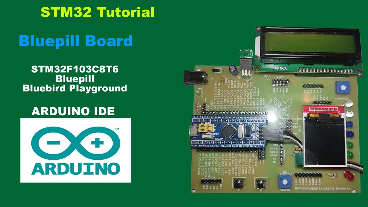
Introduction and overview of STM32 Bluepill board | STM32 Tutorial
408
This comprehensive section covers ARM microcontroller architecture fundamentals. STMicroelectronics, a French-Italian joint venture, designs microprocessor architectures and licenses them to manufacturers like Samsung and Philips. ARM architecture is designed for low cost, energy efficiency, and high performance, used in smartphones, laptops, servers, and supercomputers with over 232 billion units produced in 2022. The Cortex-M series (M0, M1, M3, M4) targets embedded applications with varying complexity: M0 for simple sensors, M3 for mathematical processing with DSP and FPU, and M4 for advanced features. The STM32F103C8T6 is a 32-bit Cortex-M3 microcontroller operating at 72 MHz with 64KB Flash, 4KB RAM, 10-channel 12-bit ADC, 3 UART interfaces, and 37 GPIO pins. Most instructions execute in single clock cycles, improving performance. The Blue Pill is a popular open-source development board using this microcontroller, named after its blue USB connector, providing a cost-effective platform for learning embedded systems development.
Click to watch →

ARM CORTEX M3 Instruction set Session 1
14.4K
The ARM Cortex-M3 is a 32-bit processor with two instruction sets: 32-bit ARM and 16-bit Thumb (compressed for memory efficiency). It has 37 total registers with 30 general-purpose registers available. Key registers include R13 (stack pointer), R14 (link register), and R15 (program counter). Three PSRs exist: CPSR (reflects operations), SPSR (saved during exceptions), and APSR. The processor operates in multiple modes: User mode (all registers accessible), FIQ, SVC, ABORT, IRQ, and Undefined modes. In User mode, all registers plus CPSR are accessible; in other modes, register banking applies with only SPSR accessible. This architecture enables efficient context switching during interrupts and exceptions.
Click to watch →
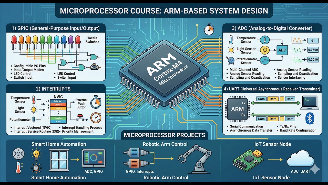
2026 마이크로프로세서(STM32F103RB, Nucleo) 강의 - 1
193
STM32F103RB는 STMicroelectronics에서 만든 32비트 ARM Cortex-M3 기반의 마이크로컨트롤러로, 72MHz 클럭, 128KB 플래시 메모리, 20KB SRAM을 갖추고 있으며, Nucleo 보드에 장착되어 교육용으로 사용됩니다. 이 보드는 USB를 통해 전원을 공급받아 기본적인 LED 제어와 스위치 입력을 학습할 수 있으며, STM32CubeIDE와 STM32CubeMX 프로그램을 사용하여 C/C++로 프로그래밍할 수 있습니다. ARM 아키텍처는 Reduced Instruction Set Computing(RISC) 방식으로 설계되어 간단한 명령어 집합을 통해 하드웨어를 최적화하고 전력 효율성을 높였으며, 이는 스마트폰, 태블릿, IoT 장치 등 99% 이상의 모바일 기기에 사용되고 있습니다.
Click to watch →
Deep Dive
Familiarity with Serial Wire Debug (SWD) and JTAG communication protocols used for programming and debugging hardware.
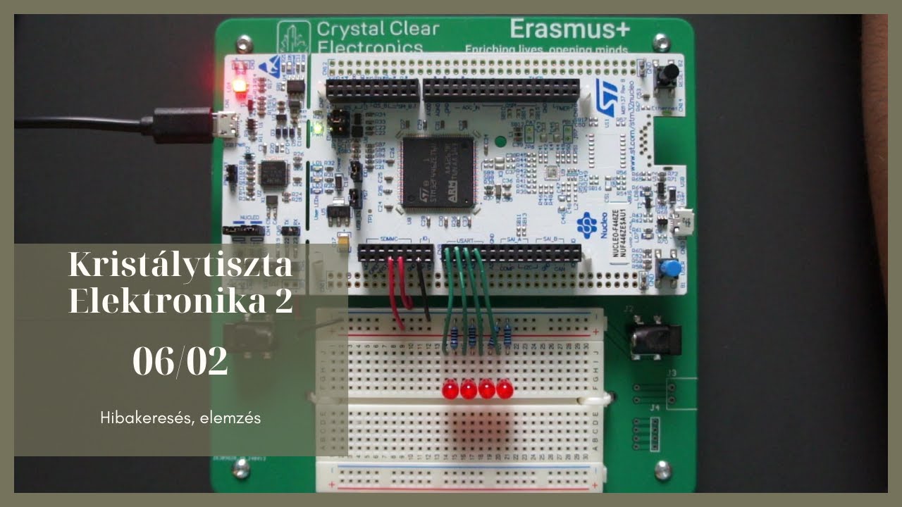
06/02 - Hibakeresés, elemzés
207
JTAG (Joint Test Action Group) and SWD (Serial Wire Debug) are standardized debugging protocols that enable communication with microcontrollers for programming and debugging. JTAG uses four essential signals (TDI, TDO, TCK, TMS) plus two optional signals (TRST, RTCK), supports boundary scanning for detecting soldering defects, and works with multiple microcontroller architectures. SWD is simpler with only two signals (SWDIO, SWCLK) plus an optional trace output (SWO), offers higher data transfer rates, but only works with ARM architecture microcontrollers. The choice between them depends on application needs: SWD is preferred for simple programming and debugging on ARM devices, while JTAG is better for complex systems, high-volume manufacturing, or when boundary scanning is required.
Click to watch →

Airfrog - how it gives root access to ARM MCUs
2.1K
SWD is a serial protocol with two lines: clock (host-controlled) and data (bidirectional). Communication follows three phases: command byte, acknowledgement, and data transmission. Turnaround (TRN) cycles allow data line control transfer between host and target. Write operations transmit 32-bit data plus parity after acknowledgement. Read operations differ—no turnaround before data transmission since target already controls the line. The command byte includes AP/DP bits, read/write flags, and address bits. All communication goes through debug and access port registers, which act as intermediaries to physical peripherals.
Click to watch →

KiCad 9 Hardware Design Tutorial (TI MSPM0) (1/2 Schematic) - Phil's Lab #165
104.9K
Cortex-M0+ microcontrollers support Serial Wire Debug (SWD) using two pins: SWDIO (data I/O) and SWCLK (clock). The debug interface typically includes VDD, GND, NRST, SWDIO, SWCLK, and optionally SWO (trace output). Tag Connect cables provide pogo-pin interfaces that clamp to PCB pads without requiring soldered components. The debug header connects to programmer/debugger tools like J-Link or TI's XDS110.
Click to watch →

What Are JTAG And SWD And How Do They Debug Embedded Systems? - Your Engineering Future
598
JTAG (Joint Test Action Group) and SWD (Serial Wire Debug) are standardized debugging interfaces used in embedded systems development; JTAG provides a comprehensive serial communication protocol with multiple dedicated pins (test data in/out, test clock, and control signals) for accessing internal registers, memory, halting processors, and stepping through instructions, while SWD offers a more streamlined two-pin solution (data and clock) specifically designed for ARM-based microcontrollers, making it ideal for space-constrained designs while maintaining similar debugging capabilities such as processor halt, memory access, and breakpoint setting.
Click to watch →
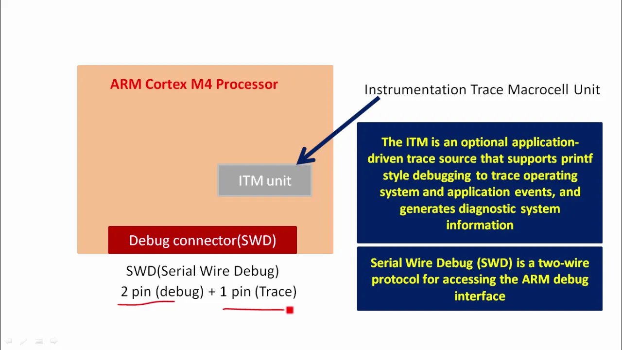
Lecture 6: Embedded 'Hello world" using ARM Cortex M4 ITM and SWO
9.4K
SWD (Serial Wire Debug) is a two-wire protocol for ARM debug interface, designed to reduce pin count from JTAG's four pins to just two. SWDIO carries debug commands and SWCLK provides the clock signal. The ST-Link circuitry manages these pins to program the microcontroller, access memory regions, add breakpoints, and control CPU execution. SWO is an optional third pin for trace functionality. JTAG was the traditional mechanism for ARM7/ARM9 families but SWD was introduced for Cortex-M family to reduce pin requirements.
Click to watch →
Deep Dive
Understanding the role of flight controller firmware (such as Betaflight or Cleanflight) and how it interfaces with sensors and actuators.
Tuto : CONFIGURER BETAFLIGHT 4.3, 4.4, 4.5... de A à Z !
49.3K
Betaflight is an open-source firmware for flight controllers that control multirotors. The Betaflight Configurator is a graphical application for flashing and configuring firmware. Targets are configuration files describing how specific flight controllers are laid out. To flash firmware, connect the FC to the PC, select the appropriate target, and choose the desired version. After flashing, apply default settings and calibrate the accelerometer. The Installation tab displays firmware version, target information, detected sensors, and real-time battery voltage and CPU usage. The Ports tab manages UARTs for connecting peripherals like receivers, GPS units, and VTX devices. The Configuration tab displays gyro frequency and PID loop frequency, which is the core control system translating stick inputs into motor commands. Options include enabling stabilizers, barometers, and compasses. Users can enter model and pilot names for OSD display. The arm angle limit prevents accidental armament when the FC is tilted. Air Mode maintains minimum throttle when the throttle stick is released. GPS configuration allows configuring GPS-specific settings and orientation correction. Beep configuration allows using the onboard buzzer or motors to indicate conditions. The Presets tab allows loading pre-configured settings for specific components. The Failsafe tab configures quad behavior when radio signal is lost. Configuration files can be saved and restored as text files for backup and transfer between flight controllers.
Click to watch →

Cleanflight / Betaflight Configuration Overview
92.7K
This tutorial provides a comprehensive overview of configuring flight controllers for RC aircraft, covering essential settings including sensor management (disabling unused sensors like accelerometer, barometer, and magnetometer to conserve resources), ESC and motor configuration (setting minimum and maximum throttle values to 1000-2000 for modern ESCs, calibrating ESCs properly, and understanding the importance of minimum throttle settings), receiver configuration (ensuring correct stick throws from 1000-1500-2000), PID tuning fundamentals, loop time optimization (typically 500us for most users), and CLI commands for system monitoring, backup, and restore operations. The presenter emphasizes that while Cleanflight is more stable, Betaflight offers newer features that haven't been ported back, making it preferable for staying current with developments.
Click to watch →

Betaflight for Beginners | The settings you need to get your drone in the air
50.8K
Betaflight is flight controller software that connects to drones via USB for configuration and monitoring. Before connecting, remove propellers for safety and ensure VTX antenna is connected. Download the latest configurator (10.7.0) and connect your drone. The Setup Tab displays orientation with an arrow indicating the front, which should correspond to actual movement. UART ports are serial communication interfaces with receive (R) and transmit (T) pins for connecting receivers and smart audio devices. Motor direction configuration determines propeller spin direction, with front motors typically spinning inward. ESC configuration sets maximum throttle percentage, and the arming angle determines minimum tilt required before arming (default 25 degrees, often changed to 180 degrees for easier recovery). The Receiver Tab verifies receiver binding by moving throttle and checking yaw, pitch, and roll responses. Flight modes include Angle mode (self-leveling with 60-degree pitch limit), Acro mode (full rate control for flips and rolls), Horizon mode (self-leveling with flip capability), and Acro Trainer (learning mode with limited control).
Click to watch →

Cleanflight / Betaflight Flight Modes | HOW TO SET UP
154.3K
Flight modes in Betaflight and Cleanflight are configured by mapping transmitter switches to auxiliary channels (typically channels 5-8), then assigning flight mode functions to those channels using range sliders in the modes tab, allowing users to control modes like Angle Mode, Horizon Mode, Air Mode, and Beeper through switch positions.
Click to watch →

كورس الطائرات المسيرة | نظام التحكم | p5
12.3K
A flight controller contains a CPU, flash memory, wireless receiver, and control outputs connecting to Electronic Speed Controllers (ESCs) that regulate motors. The primary sensors include: gyroscope (measures rotation around X, Y, Z axes), accelerometer (measures acceleration for orientation), barometer (measures atmospheric pressure for altitude calculation), GPS (determines Earth position), magnetometer (measures Earth's magnetic field), and optional airspeed sensor. These sensors work together to provide comprehensive flight data for precise control and stable flight operations.
Click to watch →
Deep Dive
Basic electrical safety and connection practices, including pinout identification (VCC, GND, SWDIO, SWCLK) on embedded boards.
KiCad 9 Hardware Design Tutorial (TI MSPM0) (1/2 Schematic) - Phil's Lab #165
104.9K
Cortex-M0+ microcontrollers support Serial Wire Debug (SWD) using two pins: SWDIO (data I/O) and SWCLK (clock). The debug interface typically includes VDD, GND, NRST, SWDIO, SWCLK, and optionally SWO (trace output). Tag Connect cables provide pogo-pin interfaces that clamp to PCB pads without requiring soldered components. The debug header connects to programmer/debugger tools like J-Link or TI's XDS110.
Click to watch →

BLHeli32 is dead. What now? // HOW TO FLASH AM32
85.6K
The SWD (Serial Wire Debug) interface requires connecting three pins: SWDIO (data line), SWCLK (clock line), and GND (ground). On the ESC circuit board, these pins are typically found as small pads adjacent to each MCU. Identifying which pads correspond to which functions may require visual inspection of trace routing from the pads to the MCU pins. Some ESC designs make this more obvious than others. Users must carefully connect the ST-Link programmer wires to the correct pads in the proper order (SWDIO and SWCLK have specific roles).
Click to watch →

Tem Dificuldades em Entender as PLACAS e Circuitos ELETRÔNICOS? FAÇA isso Agora - Eletronica Facil
37.7K
The microcontroller datasheet shows the pinout, including VCC (positive power) and GND (ground) pins. These pins are typically at opposite ends of the package. Tracing from these pins leads to the voltage regulator.
Click to watch →

Tutorial Como fazer um Direct Drive!! Programaçao! Video#4 (how to do a direct drive?)
6.1K
The ST Link programmer requires precise pin connections to the STM32 microcontroller for successful programming. The VCC (power) pin connects to the first pin on the left side of the board, near the USB module. The SWDIO (data output) pin connects to the second pin, identified by a notch mark on the board. The SWCLK (clock) pin connects to the third pin, adjacent to SWDIO. The GND (ground) pin connects to the last pin on the opposite side from VCC. These four pins must be connected using appropriately colored wires (red for VCC, orange for SWDIO, green for SWCLK, yellow for GND) to establish proper communication between the programmer and the microcontroller.
Click to watch →

A Beginner's Guide to Microcontrollers
93.2K
Each microcontroller family has its own specific connection method to programmer devices. For AVR microcontrollers, the connection uses VCC and ground pins for power, plus MOSI, MISO, and SCK pins forming the SPI port. For STM32 microcontrollers, the connection uses RST, SWCLK, SWDIO, and SWO pins forming the SWD protocol port. These pin configurations are standardized within each family, so understanding the specific pinout for your chosen MCU family is essential for proper connection.
Click to watch →
Prerequisite Knowledge
- Concept 01Basic understanding of microcontroller architecture, specifically the ARM Cortex-M3 processor used in the STM32F103 series.
- Concept 02Familiarity with Serial Wire Debug (SWD) and JTAG communication protocols used for programming and debugging hardware.
- Concept 03Understanding the role of flight controller firmware (such as Betaflight or Cleanflight) and how it interfaces with sensors and actuators.
- Concept 04Basic electrical safety and connection practices, including pinout identification (VCC, GND, SWDIO, SWCLK) on embedded boards.
Subsequent Learning
- Step 01Setting up a full development environment (like STM32CubeIDE) to write, compile, and debug custom C/C++ firmware.
- Step 02Using GDB (GNU Debugger) with the ST-Link for real-time hardware-in-the-loop debugging, setting breakpoints, and inspecting memory registers.
- Step 03Understanding bootloader mechanics, including how to recover or 'unbrick' a device using STM32 system boot modes (BOOT0/BOOT1 pins).
- Step 04Transitioning to more advanced ARM Cortex-M4 or M7 microcontrollers (such as STM32F4 or STM32F7) commonly used in modern flight controllers.
Setup & Connect
Erase & Prep
ESP Wiring
Link Success
Setup & Connect
0:00Playing Section
- 1
Initializes Flashing Tool and connects to the flight controller.
- 2
Selects target interface and establishes serial connection.
Obsolescence of F1 Hardware and the Standard of USB DFU Flashing
While learning to use an ST-Link debugger on an STM32F103 flight controller teaches fundamental embedded systems concepts, this approach is largely obsolete in modern drone building. First, the STM32F103 (F1) processor is deprecated; major flight firmware projects like Betaflight and INAV have dropped support for F1 chips in favor of F4, F7, and H7 processors due to flash memory and processing limitations. Second, using an ST-Link requires direct connection to SWD pins, which often demands delicate soldering and risks shorting the board. In contrast, modern flight controllers utilize built-in USB DFU (Device Firmware Upgrade) bootloaders. This allows users to flash firmware directly over a standard USB cable using software configurators, rendering external hardware programmers like the ST-Link unnecessary for standard firmware updates. Instructing students on ST-Link flashing for F1 boards may focus their skills on outdated hardware and overly complex workflows instead of current industry-standard practices.
Deep Dive
Setting up a full development environment (like STM32CubeIDE) to write, compile, and debug custom C/C++ firmware.

STM32 Cube IDE ile Hızlı Başlangıç
57.3K
This tutorial demonstrates how to set up STM32CubeIDE for embedded development, covering software installation, driver configuration, project creation with microcontroller selection, HAL library integration, and the complete process of writing, compiling, and flashing code to an STM32 Nucleo development board to achieve the 'zero point' where you can successfully program your microcontroller.
Click to watch →

Изучаю STM32!
209.8K
STM32CubeIDE is a powerful integrated development environment for STM32 microcontrollers. It allows users to select microcontrollers based on parameters, configure all peripherals, program and flash the device, and debug using imported breakpoints. The environment also provides real-time register viewing. The built-in programmer can be used for both programming and debugging, making it a convenient tool for development.
Click to watch →
Изучаем STM32. Как изучить микроконтроллеры за несколько недель. Набор для изучения STM32 до 1000 р.
98.4K
STM32CubeIDE is the official free IDE from STMicroelectronics for STM32 development. It provides code editing, compilation, and debugging capabilities. The IDE is available for multiple operating systems and can be downloaded from the ST website. Installation involves running the installer wizard, which sets up the development environment with default settings.
Click to watch →

STM32 + SWD + ST-Link + CubeIDE | Debugging on Custom Hardware Tutorial - Phil's Lab #4
127.7K
STM32CubeIDE combines STM32CubeMX peripheral configuration with a complete development environment for programming, debugging, and flashing STM32 microcontrollers. To create a new project: File > New > STM32 Project, select your specific STM32 part number (e.g., STM32F405VG), choose a project location and name, and configure options like copying only necessary library files. The IDE generates all required initialization code based on your peripheral selections.
Click to watch →
STM32 - программирование для начинающих. Пошагово. CubeMX CubeIDE
506.9K
After configuring settings in STM32CubeMX, the 'Generate Code' button creates the project structure in STM32CubeIDE. The generated code includes initialization functions for all configured peripherals, with user code insertion points marked by 'USER CODE BEGIN' and 'USER CODE END' comments. This ensures custom code persists through regeneration. The project can be compiled using the hammer icon, and programmed to the target board using the play button.
Click to watch →
Deep Dive
Using GDB (GNU Debugger) with the ST-Link for real-time hardware-in-the-loop debugging, setting breakpoints, and inspecting memory registers.

Debugging STM32 Arduino
16.2K
This segment demonstrates the complete GDB debugging workflow for embedded systems. The process involves: loading the compiled executable into GDB, connecting to the STUtil server using 'target extended remote localhost:234', loading the program into the target board with the 'load' command, setting breakpoints in the loop function, stepping through code using 'next' and 'step' commands, printing variable values, and analyzing the call stack with 'backtrace'. The STLink device functions as a JTAG adapter, enabling real hardware debugging by inspecting actual chip registers and memory. This workflow allows developers to debug embedded code on actual hardware rather than simulation.
Click to watch →

This Is 100% How You Should Be Debugging | How to Use OpenOCD to Debug Embedded Software with GDB
95.4K
OpenOCD is a powerful open-source debugger that enables embedded developers to debug ARM-based microcontrollers like the STM32F103C8 'Blue Pill' by connecting via common probes (such as ST-Link) and providing a Telnet/GDB interface; the debugging workflow involves installing OpenOCD and gdb-multiarch, configuring the interface and target with appropriate configuration files, establishing a remote debugging session with GDB using 'target extended-remote localhost:3333', and utilizing commands like breakpoints, step-through execution, register inspection, and memory examination to analyze and debug embedded code without relying on print statements or LEDs.
Click to watch →
Debugging Embedded Systems With GDB?
57.6K
This video demonstrates how to use GDB (GNU Debugger) for debugging embedded systems by connecting it through an intermediary tool (mspdebug) to a microcontroller like the TI MSP430, showing the complete workflow including proper compiler flags (-O0, -g3, --gdwarf-2), establishing a remote debugging connection, setting breakpoints, inspecting variables, and stepping through code, while emphasizing that this approach is more effective than print-style debugging for embedded development.
Click to watch →
![[경희대 김동한] 2020-2 임베디드시스템설계 (22)](https://i.ytimg.com/vi/AeaelRTep9s/maxresdefault.jpg)
[경희대 김동한] 2020-2 임베디드시스템설계 (22)
1.4K
Hardware debugging provides comprehensive visibility into microcontroller operation: (1) Connect via SWD (Serial Wire Debug) interface, (2) Use Keil uVision or STM32 ST-Link Utility, (3) View CPU registers and memory in real-time, (4) Set breakpoints and step through instructions, (5) Monitor variables using watch windows. These tools allow debugging without modifying code, provide faster response than software methods, and can monitor internal register values directly. STM32 ST-Link Utility is free and provides variable import capabilities. Hardware debugging is essential for understanding program flow, identifying timing issues, and debugging high-speed operations where software printing would miss changes.
Click to watch →

Tutorial: Debugging Embedded Devices Using GDB - A Review of Some Lessons Learned - Mike Anderson
18.3K
GDB provides multiple breakpoint types: software breakpoints (b command) substitute trap instructions at specified locations, while hardware breakpoints (hbreak) use processor registers and don't modify code—essential for debugging flash memory. Hardware breakpoints are limited by processor architecture (x86 has 3, ARM has 3-4). Conditional breakpoints execute only when conditions are met but substantially slow execution. Watchpoints stop execution when memory addresses or symbols are accessed: 'watch' on writes, 'rwatch' on reads, 'awatch' on either. Thread-specific watchpoints limit stopping to particular threads. Multithreaded debugging uses 'info threads' to show active threads, with breakpoints set to trigger on specific threads. Scheduler locking controls whether hitting a breakpoint stops all threads or just the triggering thread. Core dumps capture memory snapshots including register sets and stack pointers at application termination, enabling post-mortem debugging.
Click to watch →
Deep Dive
Understanding bootloader mechanics, including how to recover or 'unbrick' a device using STM32 system boot modes (BOOT0/BOOT1 pins).
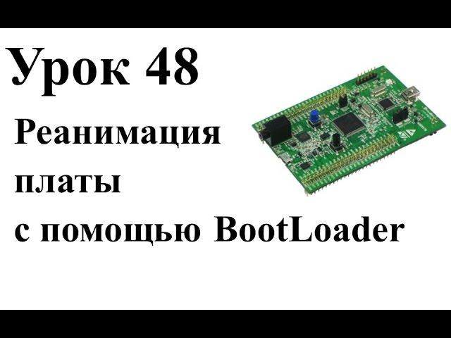
Stm32 Урок 48: Реанимация платы с помощью BootLoader
4.5K
The STM32 microcontroller features a built-in bootloader that enables programming when standard methods fail; by connecting Boot0 to VDD and Boot1 to GND, the device loads from system memory, allowing recovery through USART using ST's official programming software, which can erase corrupted flash memory and restore functionality.
Click to watch →

STM32 Basics #2 - Boot Modes
2.1K
The STM32 Boot0 pin determines which memory location is mapped to address 0x00000000, where the MCU always boots from; when Boot0 is low, the MCU boots from main flash memory, when Boot0 is high and Boot1 is low, it boots from the embedded bootloader in system memory, and when both Boot0 and Boot1 are high, it boots from embedded SRAM.
Click to watch →
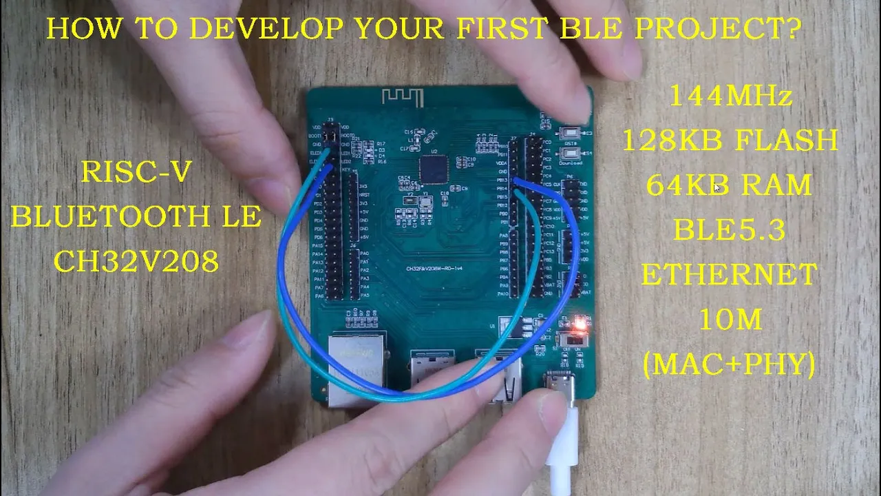
#3- How to develop a Bluetooth-LE project using RISC-V CH32V208 | PART 1
3.2K
The CH32V208 development board includes 5V to 3.3V power module, 32MHz external high-speed clock, 32.768kHz external low-speed clock, antenna for BLE communication, Ethernet interface, three USB ports, power select pin, all GPIO ports, bootloader entry key (BOOT0), reset key, two LED indicators, and custom key. Boot mode selection: BOOT0/BOOT1 pins determine boot source. BOOT0 low/BOOT1 low: user flash boot. BOOT0 low/BOOT1 high: system memory boot (bootloader for reprogramming). BOOT0 high/BOOT1 high: embedded SRAM boot. Jumper pulls BOOT0/BOOT1 low after power-on, pressing BOOT key sets BOOT1 high for bootloader reprogramming.
Click to watch →
STM32 Tips: Talking to the on-board Bootloader
18.5K
The STM32 microcontroller includes a factory-programmed bootloader in ROM that enables communication via UART with specific settings (8-bit, even parity, 1 stop bit, auto-detectable baud rate 1200-115200). To enter bootloader mode, set the BOOT0 pin to high and perform a hard reset by cutting power. Commands are sent as command bytes followed by their complement (e.g., 0x00 with 0xFF), with acknowledgments: 0x79 for success, 0x1F for failure. Key commands include: 0x7F to start command mode, 0x00 (with 0xFF) to get version and supported commands, 0x21 (with 0xDE) to jump to user application at address 0x08000000, and 0x43 (with 0xBC) to erase flash, followed by 0xFF 0x00 for global erase. The bootloader cannot be used simultaneously with ST-LINK debugging.
Click to watch →

STM32N6 demo workshop - 04 Booting process theory
2.1K
The STM32N6 supports multiple boot modes determined by BOOT0 and BOOT1 pins. Developer boot mode (BOOT1 high) enables debug interface and executes code from internal RAM for rapid testing, though code is volatile. System bootloader mode (BOOT0 low, BOOT1 high) accesses serial bootloader via USB/UART for production flashing. Boot from external flash mode loads FSBL from external memory (QSPI or SD card selected via OTP). The default configuration maps external QSPI to XASPY2 without OTP changes. For debugging, BOOT0 and BOOT1 on the right side enables loading applications into 511KB internal RAM or external flash using execution in place. The debug link remains open for serial bootloader access.
Click to watch →
Deep Dive
Transitioning to more advanced ARM Cortex-M4 or M7 microcontrollers (such as STM32F4 or STM32F7) commonly used in modern flight controllers.

Deep Dive w/Scott: More 7.0.0 Fixes #adafruit
1.4K
Cortex-M0 is the simplest Cortex-M core, while M4 and M7 are more advanced. M4 adds hardware floating point and more peripherals. M7 adds even more features including 2D DMA, JPEG decoder, and faster buses. The complexity increases with the number of features. The STM32H7 has a Cortex-M7 core with MPU (Memory Protection Unit), FPU (Floating Point Unit), and multiple buses. It has ITCM (Instruction Tightly Coupled Memory), DTCM (Data Tightly Coupled Memory), and AXI bus for high-speed access.
Click to watch →

How to Build a Fixed Wing Drone? | Electronics Basics
101.1K
The microcontroller is the core component of a flight controller, responsible for data processing and controlling other FC components. Modern flight controllers typically use STM32 microcontrollers from STMicroelectronics, which support communication interfaces like I2C, UART, CAN, and USB. Common variants include F4, F7, and H7 series, with F4 being sufficient for basic setups.
Click to watch →

Diatone Roma F5 is the new best FPV quad under $200
110.3K
F7 flight controllers outperform F4 controllers due to more advanced processors, additional UARTs for peripherals, and better overall feature sets. The Diatone's F7 processor with built-in Bluetooth represents a significant upgrade over F4-based systems, offering more configuration options and connectivity flexibility for advanced users.
Click to watch →
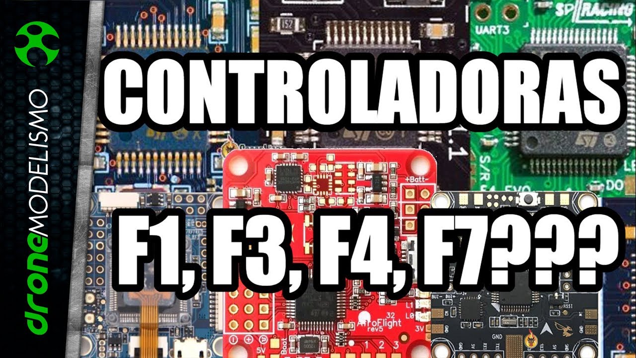
CONTROLADORAS para DRONE RACING: F1, F3, F4 e F7
15.3K
The letters F1, F3, F4, and F7 on drone controller boards refer to the STM32 processor family, which includes variants like H7, F7, F4, F3, F2, F1, F0, L4, L1, and L0. The main differences are processing speed, flash memory capacity, and expansion port count. F2 processors are obsolete versions of F4, and F5/F6 do not exist. F1 processors operate at 72 MHz with 128 KB flash memory and 2 expansion ports (one shared with USB). F3 processors also run at 72 MHz but offer 256 KB flash memory and 31 expansion ports. F4 processors operate at 168 MHz with 1 MB flash memory and 3-5 expansion ports. F7 processors operate at 216 MHz, the fastest, supporting up to 8 expansion ports. PID time is the cycle duration for controller calculations that maintain drone stability by adjusting motor speeds. Faster processors enable shorter PID times for more precise flight control. Higher-speed processors are more sensitive to vibrations from motors and propellers, requiring careful mounting with vibration-dampening materials.
Click to watch →
How to make your own Betaflight flight controller wiring diagram
206.3K
F7 flight controllers support UART inversion, making receiver connections simpler, especially for FrSky receivers. F4 processors lack this capability and require special handling for inverted protocols. Modern flight controllers primarily use F7 or F4 processors; F3 and earlier are largely obsolete. This distinction affects how you connect certain receivers, particularly those using inverted serial protocols like FrSky S-Bus.
Click to watch →
Setup & Connect
Erase & Prep
ESP Wiring
Link Success
Setup & Connect
0:00- 1
Initializes Flashing Tool and connects to the flight controller.
- 2
Selects target interface and establishes serial connection.
Obsolescence of F1 Hardware and the Standard of USB DFU Flashing
While learning to use an ST-Link debugger on an STM32F103 flight controller teaches fundamental embedded systems concepts, this approach is largely obsolete in modern drone building. First, the STM32F103 (F1) processor is deprecated; major flight firmware projects like Betaflight and INAV have dropped support for F1 chips in favor of F4, F7, and H7 processors due to flash memory and processing limitations. Second, using an ST-Link requires direct connection to SWD pins, which often demands delicate soldering and risks shorting the board. In contrast, modern flight controllers utilize built-in USB DFU (Device Firmware Upgrade) bootloaders. This allows users to flash firmware directly over a standard USB cable using software configurators, rendering external hardware programmers like the ST-Link unnecessary for standard firmware updates. Instructing students on ST-Link flashing for F1 boards may focus their skills on outdated hardware and overly complex workflows instead of current industry-standard practices.
Basic understanding of microcontroller architecture, specifically the ARM Cortex-M3 processor used in the STM32F103 series.
Familiarity with Serial Wire Debug (SWD) and JTAG communication protocols used for programming and debugging hardware.
Understanding the role of flight controller firmware (such as Betaflight or Cleanflight) and how it interfaces with sensors and actuators.
Basic electrical safety and connection practices, including pinout identification (VCC, GND, SWDIO, SWCLK) on embedded boards.
Setting up a full development environment (like STM32CubeIDE) to write, compile, and debug custom C/C++ firmware.
Using GDB (GNU Debugger) with the ST-Link for real-time hardware-in-the-loop debugging, setting breakpoints, and inspecting memory registers.
Understanding bootloader mechanics, including how to recover or 'unbrick' a device using STM32 system boot modes (BOOT0/BOOT1 pins).
Transitioning to more advanced ARM Cortex-M4 or M7 microcontrollers (such as STM32F4 or STM32F7) commonly used in modern flight controllers.
307 views4likes8:03@kiradite4321Original Release: 2020-04-21
yes how are you i doing simply to show you in it it is very gonna show you how we can use flick on to associate with it with the whole it I to say order today and we need the estate encounters jumpers or fear I mean JC and the signal of so which can flow with so see 3d okay [Music] now we connect as wcwc generally respects and read St you okay milk I use be guess not slow down hello let here goes into their light [Music] as you can see ya go directly to still open it still favor update and cheap device you see a debugger okay close it open targets and connect [Music] okay as you can see we just target connect so it's quieted if the connectors changing ago sitting and you wonder how to surf and it's worker connected what we gonna do now we got three more here is the ship easy way to target and it is you say okay again what we gonna do go turn it again and go Erie selectors and select all and apply weight samsung way to wait some minutes [Music] house you can see the ship as is is empty inside nothing while no exercise what you gonna do go disconnected and connect again okay you're fine and open you can check for this pressing or the spinning okay take it again and promote and verify don't forget to flush you can start are we gonna make a boatload of s directly to to the fly control this is really operation is wonderful working with now we are going to disconnect it a string and disconnected a steering and connected ESP directory yes but as you can see [Music] again [Music] okay and it's working out Jesse as you can see ya look it's my petunia come come my team oh okay okay now we gonna tell a disconnect sorry this finite oh okay stake [Music] okay we need ground clocked at a clock circular and we have three Vil Israel never this in American c31 and this and the black for TNT and we need this look in here okay anyway and we need another jumper which is coming from here look here we have two below choose the blue one the first plating this because we have yet it's o'clock 8 o'clock gotta see look gypsy right aren't you dating okay it's this is get it's complete what we gonna do you know connect I it's connected successful example looking for as the adversity 13 5906 and go back to see as team taciturn what you cannot do again choose this is not a protocol [Music] as you can see the oullette is working wonderful no need all these just the blue one and the 31 taking guys thank you for watching
Up Next

3:50
Truss Tension and Compression Explained | Structural Engineering Basics
@SouthernPrideOutdoor
129.9K views•2012-04-23

30:32
Ultrasonic Transducers: Resonant Frequency Measurement and Horn Design
@imajeenyus42
229.9K views•2017-02-22

54:16
Polymer Environmental Degradation: Mechanisms & Stabilization
@iit
1.8K views•2012-07-10

33:39
How a Student's Question Saved a NYC Skyscraper from Collapse
@veritasium
22.8M views•2025-04-26
Related Study Plans & Knowledge Roadmaps
Structured learning paths in Engineering
engineering
Building Acoustic Levitators: Physics & Arduino
01The Physics of Sound and Standing Waves
02Piezoelectric Transducers and H-Bridge Drivers
03Arduino Programming: Generating 40 kHz Signals
+ 2 more learning modules
14h5 modules
Explore Roadmap
engineering
Building Peltier Cloud Chambers: Particle Tracks
01Cosmic Rays & Cloud Chamber Physics
02Thermoelectric Cooling (TEC) Fundamentals
03Custom Liquid-Cooling Loop Design
+ 2 more learning modules
18h5 modules
Explore Roadmap
engineering
Yagi-Uda Antennas: Modeling, Build & VNA Test
01Introduction to RF and Antenna Fundamentals
02Yagi-Uda Antenna Design Principles
03Antenna Modeling and Simulation in 4NEC2
+ 2 more learning modules
18h5 modules
Explore Roadmap
engineering
ECG Monitor Design: Op-Amps, Filters & Noise
01Electronics & Breadboard Basics
02Op-Amps and Instrumentation Amplifiers
03Bioelectricity and ECG Fundamentals
+ 2 more learning modules
18h5 modules
Explore Roadmap