

















RC radio systems work by translating pilot control inputs into electrical signals that control servos and motors; the system uses 2.4 GHz wireless communication with binding to establish a secure connection between the transmitter and receiver, and failsafe mechanisms ensure the model returns to neutral positions if the signal is lost, with different connection types (PWM, CPPM, SBUS) determining how signals are transmitted from the receiver to the various components.
RC Radio Systems Explained: Basic Components & How They Work
Added:Basic understanding of Direct Current (DC) electricity, including voltage, current, and circuit polarity.
Fundamental concepts of electromagnetic waves and Radio Frequency (RF) communication (frequency bands, antennas).
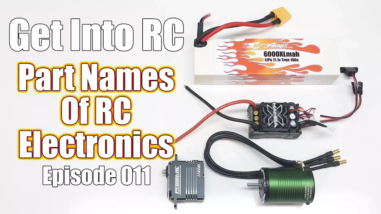
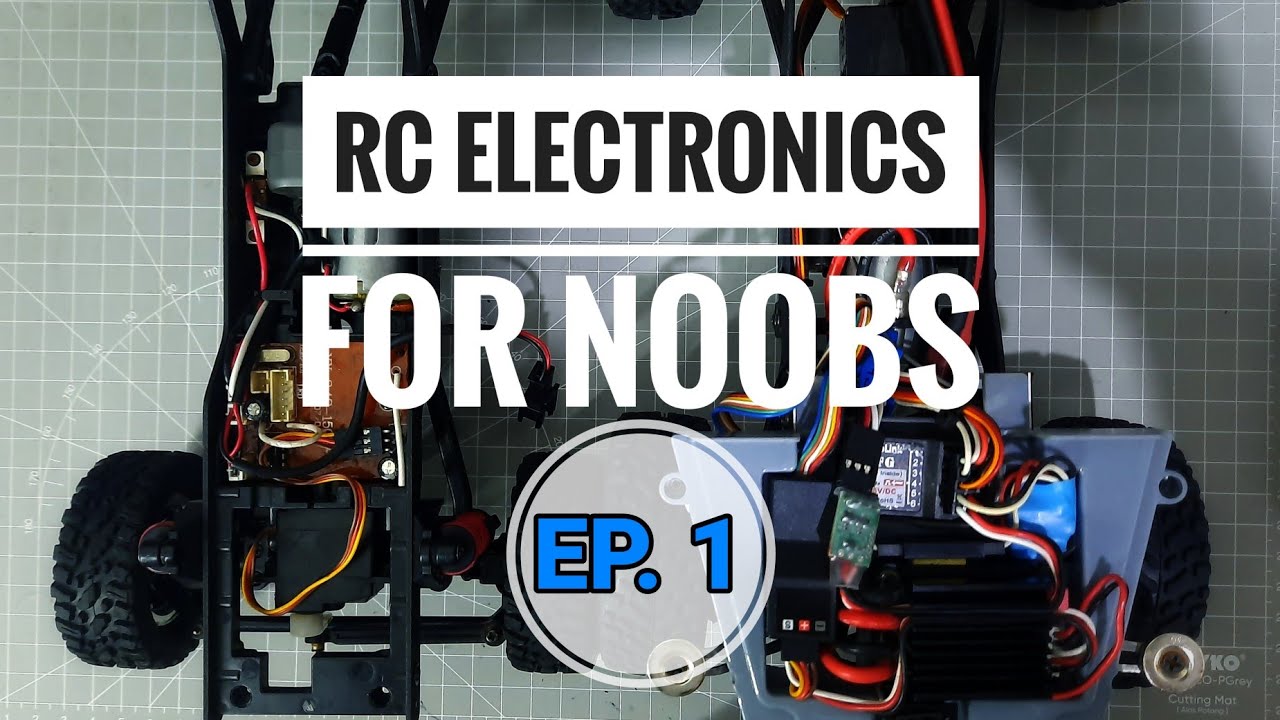
Familiarity with standard RC vehicle components such as servos, Electronic Speed Controllers (ESCs), and battery packs.
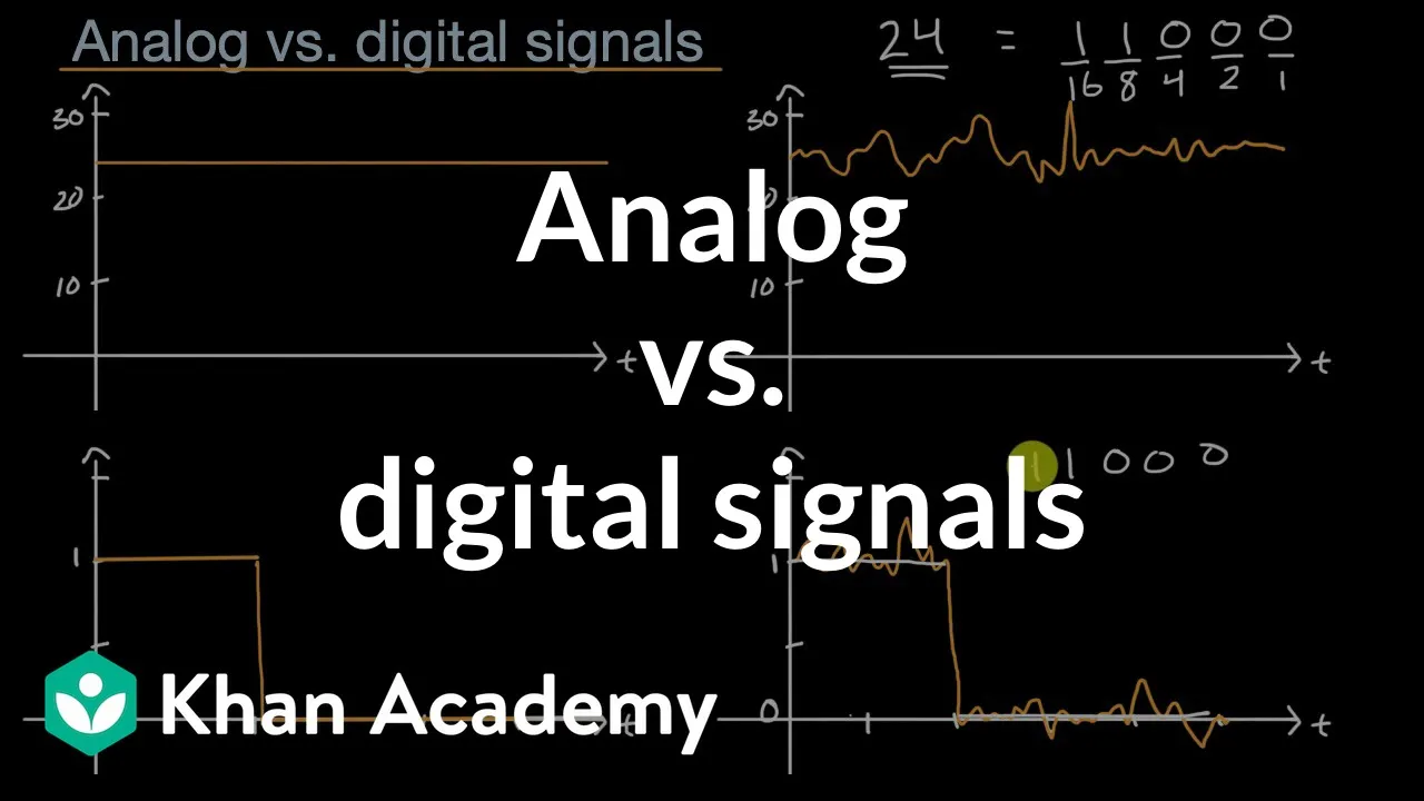
The basic concept of analog versus digital signals for transmitting information.
Advanced digital serial protocols like PPM, SBUS, and IBUS for flight controllers.
Long-range RC systems (e.g., ExpressLRS, TBS Crossfire) and the physics of 900MHz vs. 2.4GHz frequencies.
Implementing and configuring telemetry to monitor real-time battery voltage, RSSI, and GPS data.
Advanced transmitter programming, including custom channel mixing, dual rates, exponential curves (expo), and flight modes.
809.7K views11.4Klikes29:57Original Release: 2015-03-21
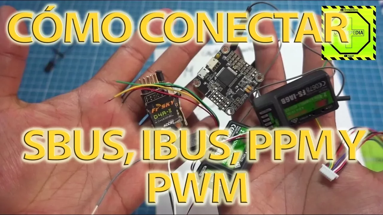
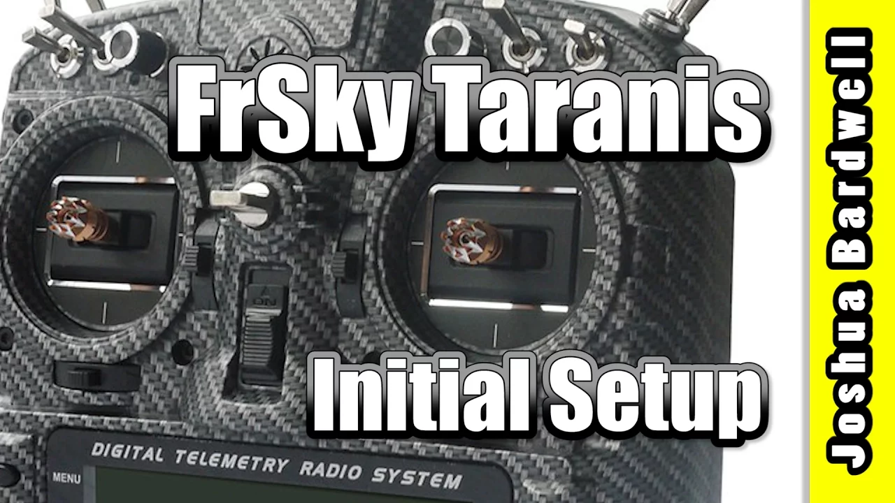
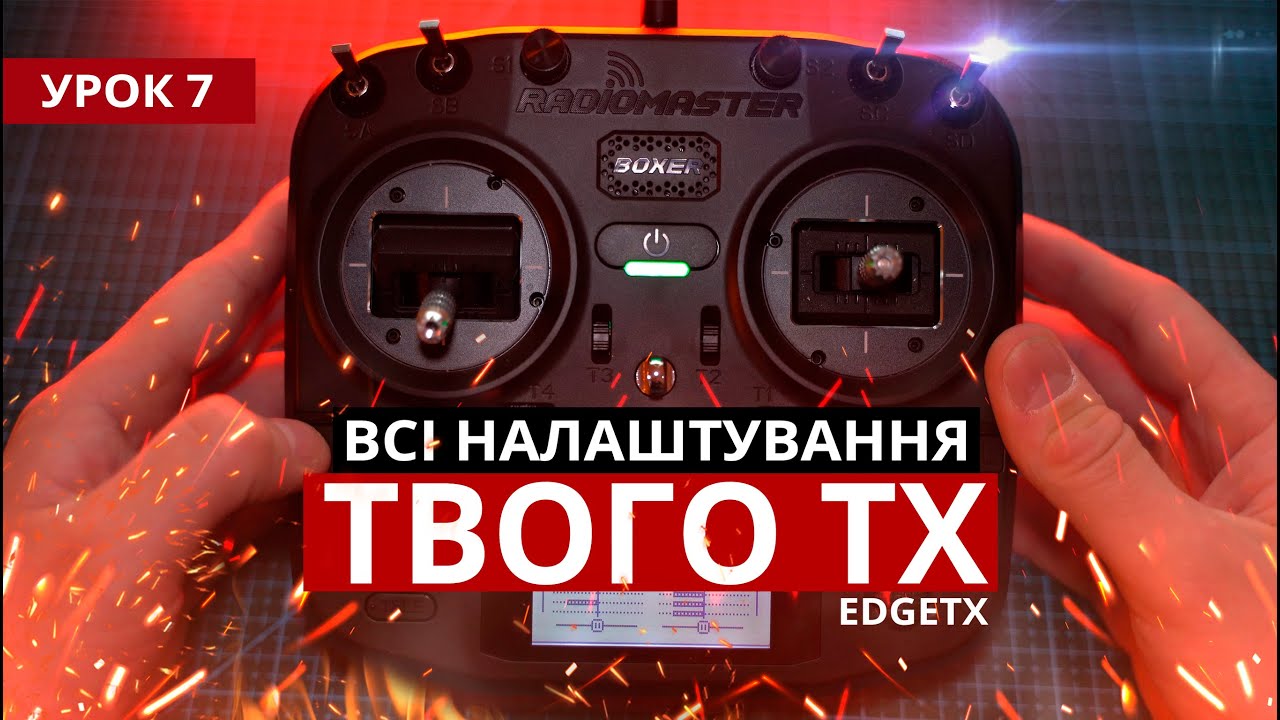
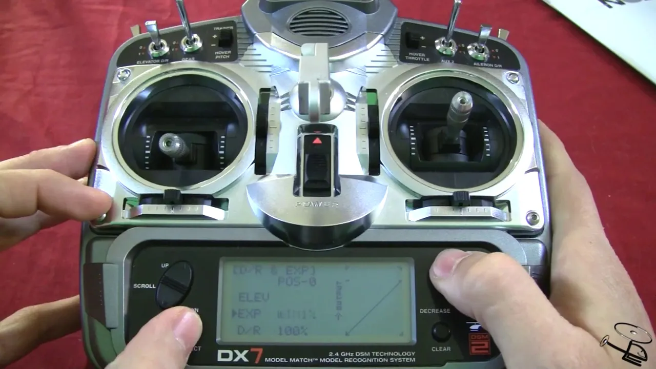
welcome to the video in this video we're going to talk about radio systems this is intended to be an introduction to radio systems for those of you who are new to remote control or coming back into the hobby after being away for a while and we're going to talk about each of the parts of the system in turn we're initially going to talk about the radio and how the radios work the different modes mode 1 mode 2 then we're going to talk about how the radio talks to the radio receiver so how that all works we're going to talk a little bit about binding why binding is used and what it does as part of that we'll talk about what failsafe is because a number of these receivers will not only bind to the radio but also remember the channel positions if they lose the connection and that's important and we'll cover why then we'll actually talk about connecting the receiver to things like servos and motors with speed controllers and how all that works together and how this little receiver is talking to the speed controller and the servo so that if I move the throttle the motors running and if I move the elevating control the servo is moving as well so we'll cover all that in this video it's not intended to be an in-depth look but the idea is if that you're coming back to RC or new to the hobby you can watch this and know enough to understand some of the acronyms that you're going to read on forums and also understand what some of the other people are telling you when you're trying to explain problems to help troubleshooting so the first place we'll start is how the basic system works you'll notice that all that's really happening is the radio is translating the movement of one of the controls into the movement of either a servo or the amount of throttle that goes into a motor and that is all the radio system is doing all of the other fancy stuff on a computerized radio the menus and everything else is all about how those two interactions work how much you have to move the stick to move the servo how much the servo moves at each end of the stick movement but very basic principle as you move the stick you move the servo or if it's connected to a speed controller the control will look after the throttle so as you see I increase the throttle you'll hear the motor get faster and faster and then slow down and you'll see as I move to stick you'll see the servo rotate and the other way like so so first of all let's talk about modes and what the modes are on the radio so the four modes that you'll come across are on the screen now modes one two three and four my radio is a mode two radio which is very common in in Europe and North America works the throttle on the left-hand side along with the rudder and the elevator and aileron on the right-hand stick you can occasionally get radios that will allow you to swap the modes and every time you swap the mode you also have to swap where the spring loading is because obviously you don't want the throttle spring loaded you want it to stay where it is for safety purposes so just be aware if you're in the forums or you're looking at a listing it's talking about a mode 1 mode 2 3 or 4 radio this is the little diagram you can refer to to figure out where everything is once people learn with the radio that tends to be the layout that they will stick with for the rest of their flying career so it's important to use the right one from the start so if we look at my radio here the way this works it's set up so we only have two things connected the throttle control obviously controls the motor the rudder ie on the tail of the plane which makes it turn in the air is on this stick on this stick over here we have the elevator which makes it rise at the model rise and forth and the nose goes up and down based on that control so that would normally be connected to the elevator at the back of the plane and then you also have the aileron control which is what makes the model roll from side to side so now we kind of understand that the next thing we probably talk about is how you bind the radio to the receiver and what that means and why we have to do it so now we're looking at a slightly simplified version of what be found before so I've taken away the motor and the speed controller because we don't need that to illustrate binding and fail-safe but we still have the servo connected to the elevator control on my radio so I move the stick upside down the servo goes one way or the other and if I reverse the channel then the servo would rotate in the opposite direction from each of my stick movement now what you have noticed is that I've had to also put something else new on the table so the way it's working is this little battery eliminator circuit which is actually part of the speed controller that I've taken off the table there's actually one of these inside here so that's why we didn't need it before this thing is providing the 5 volts that's powering the receiver and also providing the 5 volts that come out of the receiver down this cable and into the servo so that little box of tricks is giving a nice steady 5 volts that's giving my receiver in the servo all the life they need and then I'm connecting via my radio wirelessly to the little aerials on the receiver so as I move my stick the servo moves as well now the frequency of the connection between these two radios is actually 2.4 gigahertz and you'll hear that talked about on a lot of different forums but I'm using spectrum equipment here and everybody has their own favorite whether it's fr sky taranis hobbyking everybody has their own particular version of it Futaba and this just happens to the one that i have a lot of the systems use 2.4 gigahertz to talk between these two parts but actually are using a different language so it's like if you imagined that this radio is speaking English and this radio speaking English they understand each other if this was a Futaba receiver the fatah bobe's you could say for example was speaking Spanish and this radio was speaking English so in that case even though the radio was transmitting at the right frequency the receiver wouldn't understand what it was saying so you have to make sure that the receiver is going to work with your radio most modern radios when you buy them these days will come with one of these receivers in the kit in the early days of remote control the way that you got a receiver and a radio talking to each other once you knew that they were understood the same language Spanish English German or whatever is that you would put them on the same frequency and there were particular frequencies and well the way it worked is that when you went to fly you would be given a particular frequency that you could use for your flying time and you had a little radio crystal that you plug into the radio that would change the frequency that you were transmitting on that it also be a crystal that went into the receiver and that would be the way that you would talk to each other the danger of that of course was because if you had somebody else with the same frequency then your receiver could hear both radios at the same time and that could cause massive confusion and result in a crash the spectrum rate frequency technology is that most of the modern radios used these days not only use 2.4 gigahertz and different bits of the 2.4 gigahertz band but are also using digital communication to make sure that the signals that are received in the receiver are right and our error checked so if anything wacky goes on with the radio the receiver knows about it and these this information is sent in frames or packets of information around now I'm not going to go into too much detail about how all that works if you're really interested you can look at the wikis and google it and find out about it but suffice it to say that the radio and the receiver I'm not just sending one continuous stream of positions I'm actually encoding the information digitally surrounding it with error checking code and then it's going out to the receiver and if the receiver and the radio when they power up and have a noisy environment they'll hunt around on the 2.4 gigahertz frequencies they can use until they find one that works the result of all that complexity is that most of the time you turn your radio on you get the light on your receiver you have a great solid connect and you're good to fly even if there are other people around with identical radios and identical receivers because not only is the radio on the 2.4 gigahertz and they're both speaking the same language but most importantly they have a secure connection between the two so you can't accidentally turn your radio on and it bind to your friend's receiver in their plane or multi-rotor next to you the process of making that connection between your radio and your receiver is called binding you only have to do it once and once it's done then these two are a pair and they will only talk to each other and this will only activate when the radio turns on so to illustrate the point if I turn this radio off you'll see that the receiver will realize the radio is no longer there and check the connection light off if I turn the radio back on it'll take a second to connect and there we are we've got our connection back again now we need to talk about how we do the failsafe and also what that means but first of all let's go through the process of binding the receiver to the radio so we'll bind the radio to this receiver again and not only you're binding the radio and the receiver we're also binding the receiver to this radio with this specific model memory now that's important and it's as failsafe feature so that if you have a different model selected to the one that was selected when the bind happened this receiver will not power on and activate and that's great if you have two models on your radio one was for maybe a quadcopter the other one was a flying wing you'd only want the flying wing to activate when the flying wing model had been selected on your computer radio and vice versa in spectrum world it's called model match but every manufacturer pretty much has their own version of it so first of all let's make sure we're on the right and model memory this it is it's called test rig this is the one the model memory I use for all my bench testing of so we'll set this one up we're going to rebind this receiver to the radio and I'm going to go through the process for spectrum now every manufacturer's process is slightly different look in the manual or look online with the bits and pieces that came with your radio and it will talk to you about the specific process but this is how it does the spectrum it's very similar for most other manufacturers the thing that we're going to need to make this happen is we're going to need something called a bind plug now a bind plug is a special plug that will go into one of the ports of the receiver and it's usually clearly noted as battery but I'll bind and we're going to put that special bind plug into that port and then we're going to power the receiver on and what you'll notice is that the receiver will start flashing like crazy that means the receiver is just sat there waiting to hear for a connection request from the radio so let's bind to it what the wait works on this radio is you have to press and hold this button on the back as you power the radio up and then once that process is started you let go with a bind button at the back and the bind is successful will make will let confirm it or work by turning the radio off and there we are that all looks good so now we'll power down the receiver take out the bind plug power the receiver back on and we'll turn the radio back on to we'll get our connection light and now that is connected if I change the model on this radio tried to power it up it wouldn't connect to this receiver as that failsafe function brilliant that's great now if I turn the radio off we'll lose the connection light and the system will fail safe now the reason it's flashing red there is just to let me know that it's lost connection with the radio so that's binding that's the way it works so we have to bind each of the receivers to the radio and the specific model memory that we're interested in now the next thing we'll do is that's actually rebind this because not only do receivers store the connection and the security handshake between this receiver the radio on the model memory but a number of receivers also have failsafe now what failsafe is is when they receive a first boots up it has to be sending something out of all these channels while it's waiting for connection to the radio and also in the event that it loses the connection with the radio like it just did that if a red light was flashing it also needs to continue to send out a set of positions for the servos and a position for the throttle so that the plane or whatever it is you're flying will continue or send a specific level out so that the flight control board in a multi copter can realize that something wrong with the radio and take appropriate action now as you saw the way it worked is nothing happened to the server before because the mid position that where the stick was at was the position that was saved when the bind happened but watch what happened if I bind it with a stick in a different position so let's rebind it again let's put the bind plug back in the port let's power up the receiver we'll get our flashing light let's turn the radio off so there's our flashing bind light this time I'm going to bind it with a servo or with a channel that runs the server at this low position so it's a little bit tricky but I'm going to hold that stick in its lowest position I'm going to press the button at the back that will start the bind and I'm going to turn the radio on let me hold it all until the bind happens and then let go now we have it bound again and we have control of our servo but this time watch what happens to the servo when I turn off the radio because when I bound the receiver and the radio together I have the stick in the low position that is the position that the failsafe sends all the controls to and that's what failsafe is so failsafe is that what happens on the receiver when it loses a connection it sends those positions on all the channels to all the servos and all the speed controllers or it sends all those bits of information to your flight control board on your multi rotor and and you have to be very careful about failsafe if you have it if you don't have it the danger is is that the radio continues to send the signals that it had when the connection was lost if you were at full full throttle in a dive when the radio went off the model will continue full throttle in the dive right until it hits the ground and you'll occasionally hear about something called fly aways on the forums and that sometimes what will happen if the radio connection is lost and there is no failsafe setup on the receiver then wherever the sticks were when the radio connection failed the receiver will continue to power the servos and speed controller at that level in those positions that you had it on and continue to fly the plane right out of sight and right out of your life in a fail-safe what you'd probably do is you normally make sure that the failsafe is always the throttle is off and all the positions of the control surfaces are neutral and at least that way if the radio fails then the plane will shut down its throttle and land safely or glide without going too far so that's binding and that's failsafe next thing we talk about is how all these connections work because you've probably already noticed that we have different color cables so let's have a look at these cables that we've been talking about now they're both servo cables in the end in these three connections and we'll talk about what each of these cables do in a minute but very simply ones are ground ones are +5 volts and ones are signal and you can see there are two different colors this one is the one that's connected to the servo that we've been using in the video so far but we also have this one here which is connected to the speed controller that we're using to power the motor and that has three colors as well red black and white and again one's ground ones +5 volts and one is signal if you actually look on the individual receivers themselves this one's actually easier this is a sixth channel you have the battery binds at the bottom and then it goes throttle aileron elevator rudder gear and then auxilary one and each of those channels correspond to one of the controls that we were just looking at the throttle aileron elevator and rudder or on the sticks the gear and auxilary ones are typically separate switches and you can see here that you just plug in the speed controller into things like the throttle and then you plug in servos if it was a plane into the elevator rudder now on the side normally there is a little indicator and if you can see on this one it said up it's super easy to see I'll try and get it so that catches it there's a little s and that is showing you which is the signal pin so on this one the top pins on this connector is signal the middle is +5 volts and ground so we'll look at that in a quick diagram here we have our receiver that we've just been looking at we have a battery bind portable elevator aileron rudder gear an auxilary one so this is actually and got the six channels and here are the two pins so you can see the top one there's the white one the black or brown pin is usually ground the middle pin is always +5 volts and the yellow or white is the signal so the way you install this remembering that the S is showing us the top row is the signal if we're plugging in the servo and obviously we need to make sure that the signal cable which is orange is plugged into the servo lead so let's put down to the elevator channel and the connection to the speed controller that is going to go into throttle and again we want the signal lead which is white at the top so that that is connected properly to and that's how you connect them up in your model pretty straightforward stuff some of the receivers they like this one this is a certain channel receiver from hobbyking this one interestingly doesn't have failsafe so you have to be a bit careful but it has a longer antenna and that's handy if you're going to put it inside something like a carbon fiber plane or chassis these little stubby aerials are fine the reason this - is it kind of gives you what's called diversity so depending on the orientation as you fly the craft around it gives you two chances of getting a good signal with this one this big long wire is supposed to come outside of a carbon fiber frame the reason being is that carbon fiber kind of absorbs the radio and signal that's coming from the radio because 2.4 gigahertz doesn't go through things very well at all but here you can actually see you've got the different channels listed out now they actually are going to be pretty much the same as the ones on this other receiver but on this one you have to find your manual and figure out which is which now we have connected up that's great but there's also other things that you'll read about in the forum's first one is how you connect these up so just like we're connecting up here we can connect each of the individual servos and each of the individual connections into the channels that we need this is called PWM or pulse width modulation and here's a couple of images of receivers that I've got installed on my craft that are using PWM where each of the individual channels go via a separate cable to where they're needed in the craft even things like into flight controllers for multirotors things like quad copters hexacopters etc so the way that looks is that you plug a cable into each of the individual channels that correspond to on the controls on your radio and then you connect back to whatever it's going to be so for example if it was a plane the throttles going to go to the speed controller for the motor then you're the elevator is going to go to the servo that controls the elevator at the back the aileron is going to connect to the servos out in the wings that control the other ons the rudder again is going to control connect to the serval that connects the back which can move the vertical rudder and then the gear and auxiliary switches will connect whatever you want them to it might be something like landing gear or lights or whatever that's PWM or pulse width modulation that's a very common way of putting things together the great thing about this is that when you have lots of separate servos and speed controllers that you need to plug in this is a really simple easy way to do it there's also another couple of a ways to get the signals out of your radio receiver into the craft itself now there are two versions of this I'm going to talk about ppm or pulse position modulation or C ppm it's sometimes called as well and C ppm or ppm use is one single cable and you'll normally notice like for example on these receivers these are the hobbyking are six one five X's if I plug a cable into the battery bind port that is where my ppm signal comes out of and that is all of the signals for all the other channels one after the other in a big long stream now obviously the thing you connect it into is usually a flight control board for things like multicopters and the flight control board needs to be told which order those signals are coming in on but it vastly simplifies your cabling because you only have one table that goes from the battery bind into the craft so here's a picture of one that I did with the Nazi 32 in one of my series of videos there's other versions of this which allow you to use a single cable to transfer all of your control positions to one place and that's called s bus and s bus is kind of like ppm but actually is a slightly different implementation so you can't use ppm and s + together but both of those allow you to use a single cable to get all of your controls out of your receiver without having to have six or seven wires all over your model next thing to talk about then is how do we actually get the signal from the controller on the receiver to something like the speed controller or the actual servo itself well the amazing thing is is that it actually is sending out little microscopic pulses on each of the channels or if it's ppm on one individual cable now when I plug the servo into the receiver what happens is down that signal wire the receiver is sending little pulses that are then direct relation to the position of the control on the radio so the receiver here is that the elevator is in the middle position and it sends a little pulse down the wire that's exactly fifteen hundred microseconds long and the servo hears that and says after that means I need to be in my middle position 1000 microseconds meaning a low position on the control 2,000 microseconds meaning a high position on the control so there is a little bit of electronics inside servo that understands and is measuring the width of the pulses held hence pulse width modulation pwn and positioning the servo in relation to the width of the pulses it's getting similarly the speed controller is doing exactly the same thing when we plug that into the throttle Channel the receiver is sending out the pulses in exactly the same way and the speed controller is then taking that pulse width and then converting that into a power setting for the motor and that's actually how it works so now we can start at the radio so we position the radio and controls where we want them to the radio then sends that information securely over to the receiver the receiver then receives that and then sends out on each of the channels or if it's ppm on one cable pulses that are a direct relation to the position of the controls that it's heard and there is little brains inside the servos and the speed controllers would then convert those pulses back into meaningful information and use them to either position the servo or to send more or less power to the motor so sometimes you'll see when you're setting multirotors up that there will be a range for maybe the throttle channel and you'll see ranges of things like thousand and sixty up to 1860 it's very common for things like Simon K speed controllers that's what the talking about is actually the width of the pulses that are coming from the receiver which is a direct relation to the position of the controls so normally on most radios a thousand is the low end 2,000 is the high end and 1,500 in in the middle and if you connected an oscilloscope to one of these channels and you actually move the control on the radio you'd actually see that pulse width changing all the time we have covered a lot we have talked about the radios we've talked about the modes we've talked about how the binding works what failsafe is we've talked about what pulse width modulation is how that difference from things like ppm or cppm we touched on s bus and now we've talked about how all the connections work and how the receiver talks to things like the servos and the speed controllers in your model so hopefully that was enough of an introduction to help you understand the three left acronyms and some of the bits and pieces in the forum's that you're going to read if you have any questions or comments or something that you need help with please post them below if you'd like to know more about remote control information I have a special introduction to remote control and an introduction to power system playlists on my channel please find those in addition I also have a number of videos I'm just going through now I'll put the links to these down in the bottom of the description and if you want to go and find out more about introduction to lipo batteries or radio systems or fpv or any other extra pieces you can watch these are the videos and they're written and presented in the same way so that's trying to present the complicated subject in hopefully easy-to-understand slides and visuals thank you for watching please like subscribe and happy flying
Up Next
10:48
STM32 Timer Input Capture: PWM Frequency and Duty Cycle Measurement
@Gettobyte
1.3K views•2022-05-27

30:32
Ultrasonic Transducers: Resonant Frequency Measurement and Horn Design
@imajeenyus42
229.9K views•2017-02-22

54:16
Polymer Environmental Degradation: Mechanisms & Stabilization
@iit
1.8K views•2012-07-10

33:39
How a Student's Question Saved a NYC Skyscraper from Collapse
@veritasium
22.8M views•2025-04-26
Related Study Plans & Knowledge Roadmaps
Structured learning paths in Engineering
engineering
Building Acoustic Levitators: Physics & Arduino
01The Physics of Sound and Standing Waves
02Piezoelectric Transducers and H-Bridge Drivers
03Arduino Programming: Generating 40 kHz Signals
+ 2 more learning modules
14h5 modules
Explore Roadmap
engineering
Building Peltier Cloud Chambers: Particle Tracks
01Cosmic Rays & Cloud Chamber Physics
02Thermoelectric Cooling (TEC) Fundamentals
03Custom Liquid-Cooling Loop Design
+ 2 more learning modules
18h5 modules
Explore Roadmap
engineering
Yagi-Uda Antennas: Modeling, Build & VNA Test
01Introduction to RF and Antenna Fundamentals
02Yagi-Uda Antenna Design Principles
03Antenna Modeling and Simulation in 4NEC2
+ 2 more learning modules
18h5 modules
Explore Roadmap
engineering
ECG Monitor Design: Op-Amps, Filters & Noise
01Electronics & Breadboard Basics
02Op-Amps and Instrumentation Amplifiers
03Bioelectricity and ECG Fundamentals
+ 2 more learning modules
18h5 modules
Explore Roadmap