


















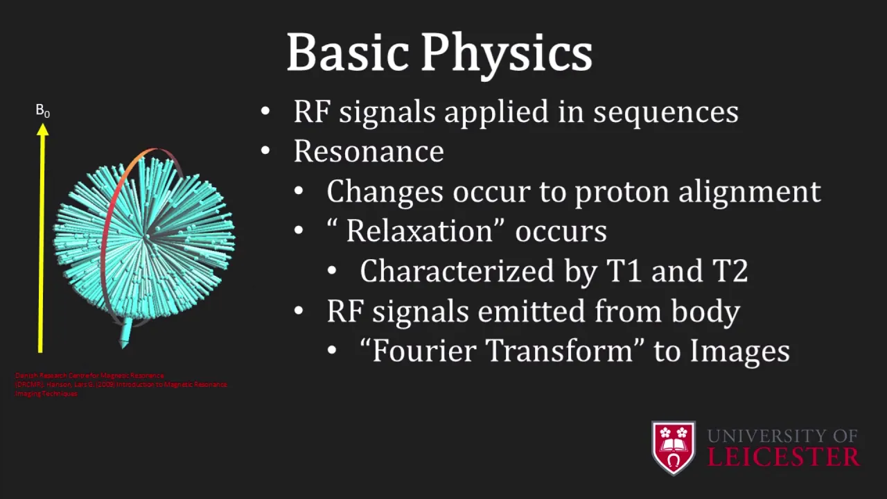

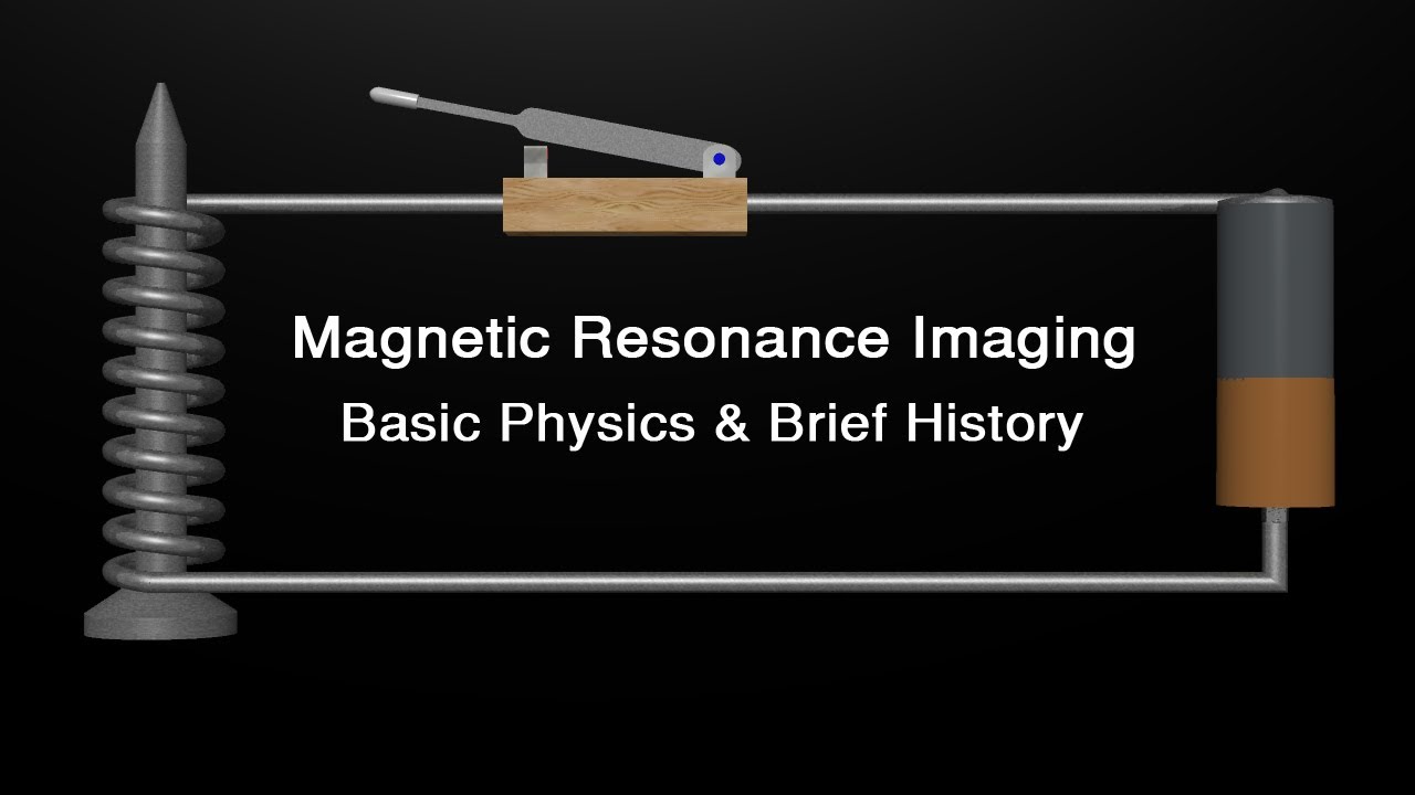
MRI uses magnetic fields and radio frequencies instead of ionizing radiation to create images by exploiting the magnetic properties of hydrogen atoms in the body's water content; the process involves aligning hydrogen protons in a strong magnetic field, using radiofrequency pulses to disturb this alignment and create transverse magnetization, then detecting the signal as protons relax back to their original state through T1 and T2 relaxation processes, with spatial encoding achieved through gradient coils that allow directional imaging along the Z, X, and Y axes.
MRI Physics Explained: Principles of Magnetic Resonance Imaging
Added:Basic Electromagnetism: Understanding magnetic fields, magnetic dipole moments, and Faraday's Law of Electromagnetic Induction.
Wave Physics and Resonance: Familiarity with radiofrequency (RF) waves, frequency, phase, and the physical principle of resonance.
Nuclear Spin and Angular Momentum: Elementary concepts of atomic structure, specifically how hydrogen protons possess 'spin' and behave like tiny magnets.
Basic Human Anatomy and Tissue Composition: Understanding that the human body is primarily composed of water and fat, making hydrogen nuclei the ideal target for clinical imaging.
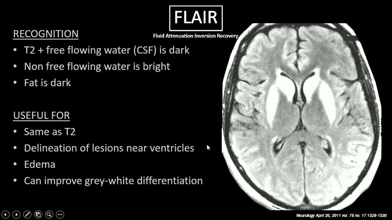
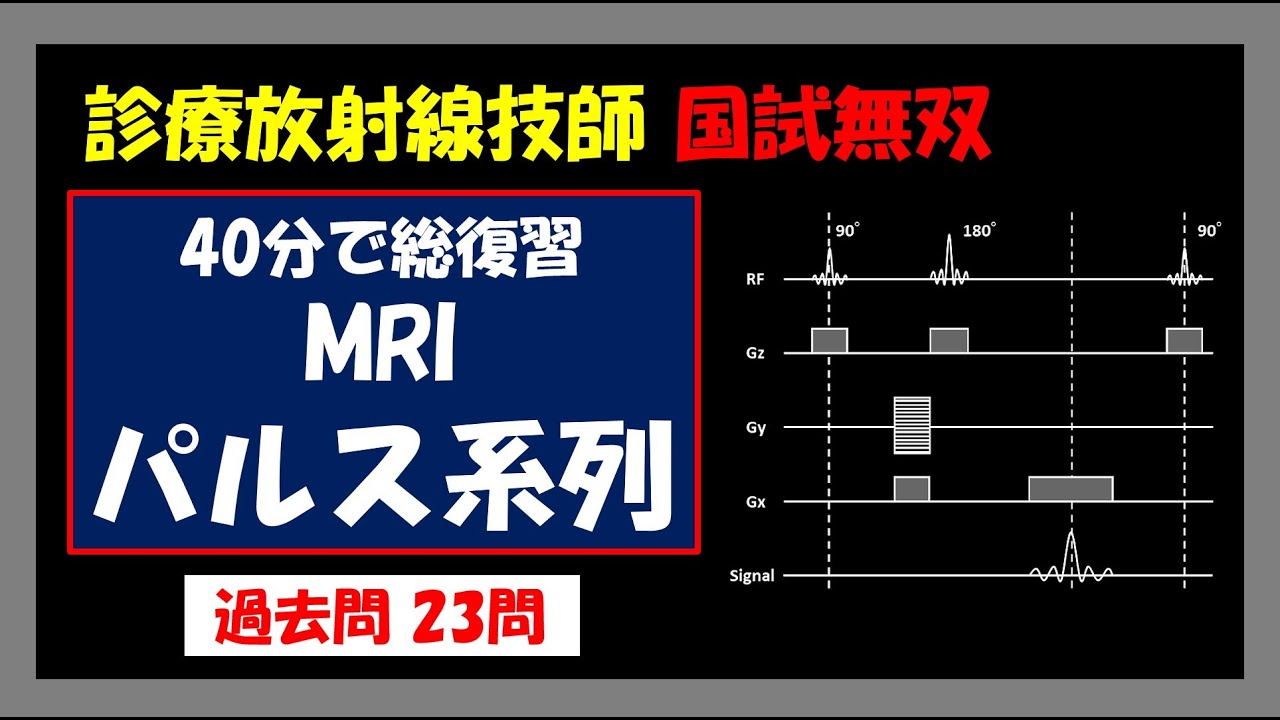
Advanced MRI Pulse Sequences: Studying specific sequences such as Spin Echo, Gradient Echo, Inversion Recovery (FLAIR/STIR), and Echo Planar Imaging (EPI).
K-Space and Image Reconstruction: Exploring how spatial encoding data is filled into k-space and mathematically converted into visual images via the Fourier Transform.
Functional and Specialized MRI Techniques: Investigating Functional MRI (fMRI), Diffusion-Weighted Imaging (DWI), and Magnetic Resonance Spectroscopy (MRS).
MRI Instrumentation, Safety, and Artifacts: Learning about superconducting magnets, gradient/RF coils, safety protocols regarding strong magnetic fields, and identifying common image artifacts.
982.9K views9.7Klikes8:40Original Release: 2013-09-25
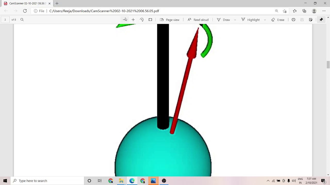
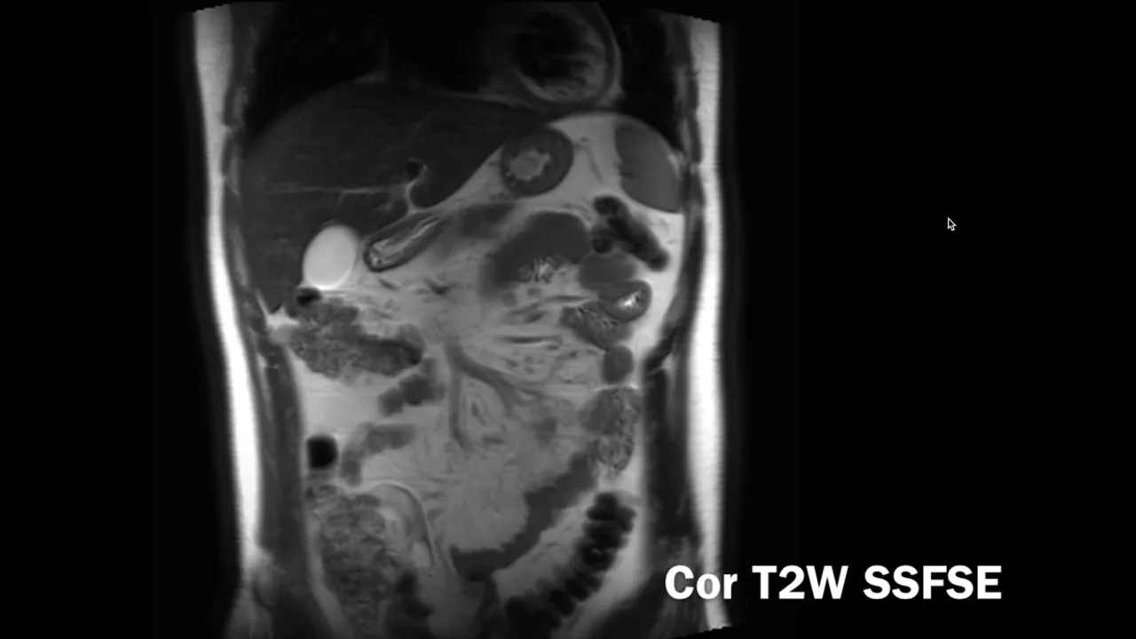
welcome to lightbox Radiology education MRI was discovered in 1947 simultaneously by two physicists Felix block and Edward pcel the first clinical images were obtained in 1977 MRI uses magnetic fields and radio frequencies rather than ionizing radiation used in X-ray and CT the magnetic field strength of an MRI machine is measured in Tesla the majority of MRI systems in clinical practice are 1.5 or 3 Tesla referred to as 1.5 or 3T these produce an extremely strong magnetic field up to 50,000 times that of the Earth's magnetic field an electromagnet of similar strength would be able to pick up a car the body is made up of 70% water which is composed osed of hydrogen and oxygen atoms MRI relies on the magnetic properties of hydrogen atoms to produce images the hydrogen nucleus is composed of a single proton with no neutrons as a spinning charged particle this produces a magnetic field called a Magnetic Moment normally the protons are orientated randomly so there is no overall magnetic field the components of the MRI system include the primary magnet gradient magnets radio frequency coils and the computer system MRI differs from Imaging such as plain film radiography and CT scanning as it uses magnetic fields and radio frequencies rather than ionizing radiation the primary magnetic field refers to the strength of the static permanent field for example at 1.5 or 3T hydrogen atoms align parallel or anti-parallel to the primary field B 0 this is called longitudinal magnetization in the long axis of the magnetic field a greater proportion of the hydrogen protons align in the direction parallel to the primary magnetic field or low energy State then a line anti-parallel to the primary magnetic field the high energy State the net result called the net magnetic Vector is therefore in the direction of the primary magnetic field this is orientated in the patient's long or Z axis the protons spin on their axes much like a spinning top this is called procession the procession rate is called the LaMore frequency when protons process together this is known as inphase when protons process separately this is known as out of phase the frequency changes in proportion to the magnetic field at 1.5 Tesla this is 63.9 MHz the gradient coils generate secondary magnetic fields over the primary field they are located within the bore of the primary magnet they are arranged in opposition to each other to produce positive and negative poles the arrangement of these gradient coils gives MRI the capacity to image directionally along the Z X and Y AIS there are three gradient coils which are named according to the axis along which they act gradient magnets alter the strength of the primary magnetic field thereby changing the procession frequencies between slices this can then be used for slice selection and localization in the X Y and Z axes called spatial encoding of Mr images The Zed gradient runs along the long axis to produce axial images the Y gradient runs along the vertical axis to produce coronal images and the XG gradient runs along the horizontal axis to produce sagittal images the radio frequency or RF coils are used for transmitting the radio frequency or RF pulse and receiving signals in MRI they come in many designs altered to best suit each body part all aiming to improve signal to noise ratios to produce the best possible diagnostic images the RF coil is used to transmit a second magnetic field or RF pulse which results in a disturbance of the proton alignment some low energy parallel protons flip to a high energy State decreasing longitudinal magnetization secondly protons become synchronized and process in Phase as a result the net magnetization Vector turns towards the transverse plane that is at right angles to the primary magnetic field this is known as transverse magnetization the radio frequency or RF coil is used to receive signals to create images as protons resume their normal state in the primary magnetic field prior to transmission of the RF pulse this is called relaxation relaxation in the longitudinal axis is T1 relaxation relaxation in the transverse axis is T2 relaxation after the RF pulse several protons flip back to their low energy State parallel to the magnetic field Z axis giving up their energy to the surroundings the lattice this results in changes to the longitudinal relaxation known as T1 relaxation or spin lce relaxation on a plot of magnetization over time magnetization increases with time this is the T1 curve the T1 relaxation time will vary depending on tissue composition and structure for example water molecules move rapidly and do not move into the lower energy State quickly so T1 relaxation takes longer after the RF pulse protons that were in Phase begin to dease in the transverse XY AIS this is known as spin spin relaxation this results in a reduction in transverse magnetization plotting transverse magnetization in the XY plane versus time transverse magnetization decreases over time in reality the spins D phase much quicker than T2 because of inhomogeneity in the magnetic field b0 the combination of T2 relaxation and field inhomogeneity is termed T2 star T2 relaxation times vary between tissues for example water molecules move quickly and as a result there is less field in homogeneity therefore T2 relaxation takes longer the net magnetic Vector is the sum of longitudinal and transverse magnetization the net magnetic Vector spirals around the Zed axis with net procession the changing Magnetic Moment of the net magnetic Vector results in free induction Decay this induces an electrical signal the signal received by the RF coil is in the transverse plane and reduces as the net magnetic Vector moves to the long or Zed AIS the computer system receives the RF signal and performs an analog to digital conversion the digital signal representing the imaged body part is stored in the temporary image space or kpace the caspace stores digitized Mr signals during data acquisition the digital signal is then sent to an image processor where a mathematical formula called fuer transformation is applied and the image of the m R scan is displayed on a monitor
Up Next
25:51
MRI Physics and a Brief History of Magnetic Resonance Imaging
@DoctorKlioze
830.5K views•2013-11-05

12:53
21cm Hyperfine Transition in Neutral Hydrogen: Radio Astronomy Basics
@AaronRobertParsons
12.4K views•2011-10-13

32:32
NMR Spin Physics I: Zeeman Effect, Resonance Condition & Larmor Frequency
@nptel-indianinstituteofsci8064
2.3K views•2024-01-17

27:14
Entropy and the Second Law of Thermodynamics Explained
@veritasium
27.5M views•2023-07-01
Related Study Plans & Knowledge Roadmaps
Structured learning paths in Physics
physics
Nuclear Physics (Decay, Fission & Reactors)
01Atomic Structure and the Binding Force
02Radioactive Decay and Half-Life
03Nuclear Fission Mechanics and Chain Reactions
+ 2 more learning modules
12h5 modules
Explore Roadmap
physics
Soft Matter (Polymers, Colloids & Rheology)
01Foundations of Soft Matter & Thermal Forces
02Polymer Physics and Macromolecules
03Colloids, Surfactants, and Self-Assembly
+ 2 more learning modules
38h5 modules
Explore Roadmap
physics
Analytical Mechanics: Lagrangian & Hamiltonian
01Mathematical Foundations: Calculus of Variations
02From Newtonian Mechanics to Constraint Dynamics
03The Principle of Least Action & Lagrangian Mechanics
+ 3 more learning modules
28h6 modules
Explore Roadmap
physics
General Relativity (Spacetime & Cosmology)
01Foundations of Relativity: Special Relativity
02The Geometry of Spacetime: Equivalence Principle & Curvature
03Einstein's Field Equations: The Mathematics of Gravity
+ 2 more learning modules
55h5 modules
Explore Roadmap