A DC motor operates based on the Lorentz force principle, where a current-carrying copper coil placed in a magnetic field experiences a perpendicular electromagnetic force that causes rotation; the stator creates the magnetic field while the armature (rotating coil) receives current through brushes and a commutator, with multiple coils ensuring continuous torque and smooth rotation throughout the motor's operation.
DC Motor Working Principle: Lorentz Force and Electromagnetic Field Explained
Added:Deep Dive
Basic concepts of magnetism, including magnetic poles, magnetic field lines, and magnetic flux.

MAGNETISM 01 | Bar Magnet | Physics | Class11th/MHTCET/JEE/NEET
39.6K
This comprehensive section covers the foundational concepts of magnetism. William Gilbert conducted systematic investigations using the scientific method and discovered that Earth itself acts as a weak magnet. Oersted suggested the link between electricity and magnetism, while James Clerk Maxwell proved they represent different aspects of the same fundamental force field. A bar magnet is a rectangular-shaped magnet with two equal and opposite magnetic poles separated by a small distance, with poles located slightly inside the ends rather than at the ends. Magnetic length (2l) is the shortest distance between poles, always less than geometric length (L), with the relationship: Magnetic Length = (5/6) × Geometric Length. Pole strength is the ability of a magnetic pole to attract magnetic material, represented as +q_m for north and -q_m for south, with SI unit ampere-meter. Magnetic moment (M) is a vector quantity defined as M = q_m × 2l, with direction from south to north pole, and SI unit ampere-meter². Magnetic field is the space around a magnet where its effect can be experienced. Magnetic lines of force originate from the north pole and terminate at the south pole outside the magnet, and run from south to north inside the magnet, forming closed loops. The direction of magnetic field at any point is given by the tangent to the magnetic line at that point. Magnetic field lines never intersect each other. The formula for magnetic field is B = Φ/A, where Φ is magnetic flux and A is area. The SI unit is tesla (T), equivalent to weber per square meter (Wb/m²). One tesla equals 10^4 gauss. The axial line passes through the south and north poles, while the equatorial line passes through the center and is perpendicular to the axial line. The magnetic field on the axial line is B_axial = (μ₀/4π) × (2M/r³), in the direction of the magnetic moment. The magnetic field on the equatorial line is B_equatorial = (μ₀/4π) × (M/r³), opposite to the magnetic moment direction.
Click to watch →

12th Physics Chapter 5 Magnetism and Matter: Complete Solution to 50 Important Objective Questions
242
This section covers the foundational concepts of magnetism. Magnetic flux (Φ) is the number of magnetic field lines passing through a surface, calculated as Φ = BA cos θ, with unit Weber (Wb). Magnetic pole strength measures the strength of north and south poles, with SI unit Ampere-meter (A·m). Magnetic moment (m) is a vector quantity describing a magnet's strength and orientation, with units Joule/Tesla (J/T) or Ampere-meter squared (A·m²). The direction of magnetic moment is from south to north pole. Magnetic field lines inside a magnet run from south to north, completing the closed loop.
Click to watch →
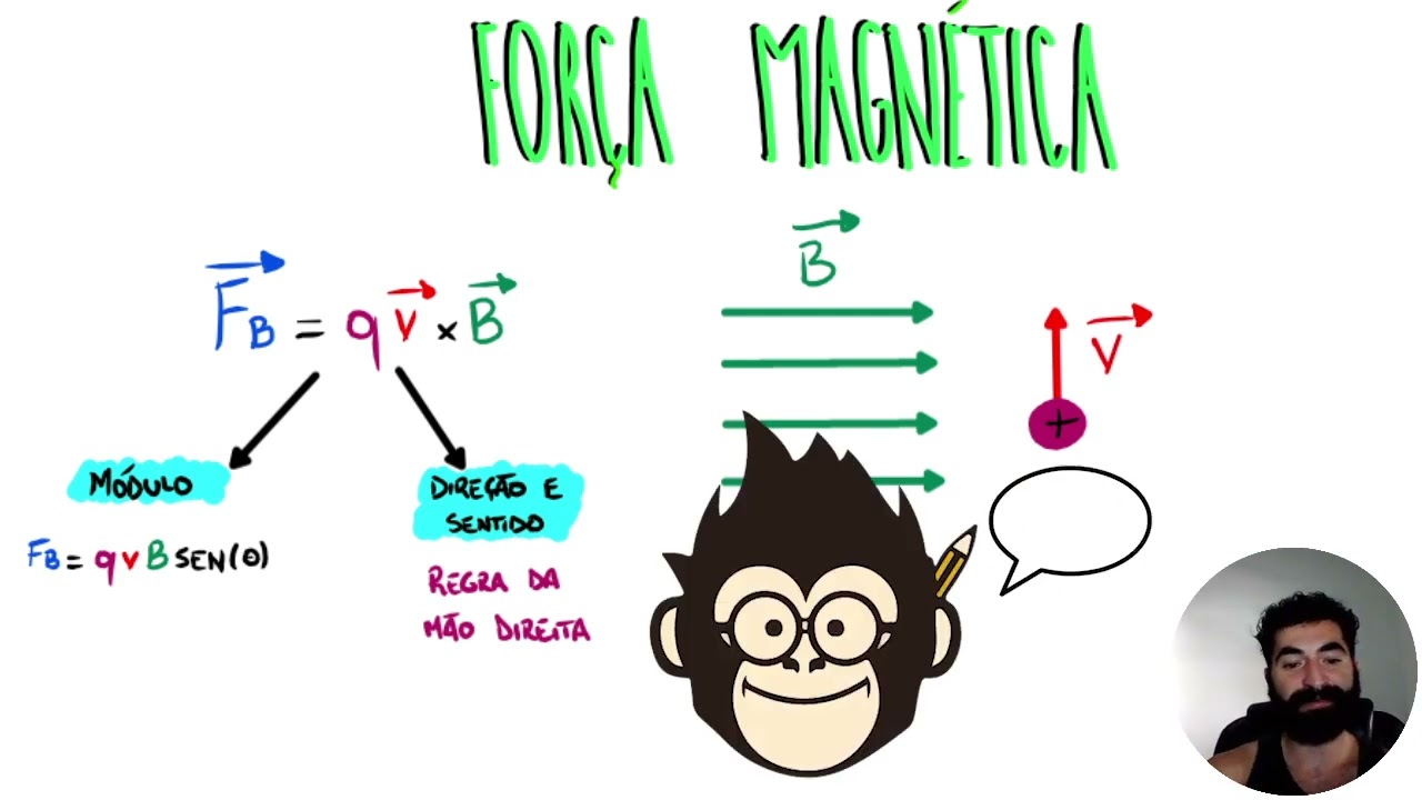
Entendendo a Força Magnética | Responde Aí
27.9K
This section covers the basic principles of magnetism including: (1) Magnetic poles always come in pairs - no isolated north or south poles exist; (2) Magnetic field lines emerge from north poles and enter south poles, creating directional flow; (3) Opposite poles attract while like poles repel, following Newton's third law; (4) Ferromagnetic materials become temporarily magnetized when near magnets, retaining residual magnetism after the external field is removed. These concepts form the foundation for understanding more complex electromagnetic phenomena.
Click to watch →

Plus Two Physics | Magnetism and Matter | One Shot Revision | Xylem Plus Two
63.7K
A magnetic field is the space around a magnet where its effects (attraction/repulsion) can be felt. Magnetic field lines are imaginary lines used to represent the magnetic field. Key properties include: (1) Field lines emerge from North pole and enter South pole outside the magnet, flowing from South to North inside, forming closed loops; (2) The direction of the magnetic field at any point is given by the tangent to the field line at that point; (3) Magnetic field lines never intersect because that would imply two different field directions at the same point; (4) A uniform magnetic field is represented by parallel, equally spaced field lines, where closer spacing indicates stronger field.
Click to watch →
Magnetic field 01
1.8K
A magnetic field line is the path that a small magnetic north pole would follow when placed in a magnetic field. It represents the direction of the magnetic field at any point. Magnetic field lines have several key properties: (1) They originate from the North Pole and terminate at the South Pole, (2) They emerge from the North Pole and enter the South Pole perpendicularly, (3) They never intersect each other, (4) The density of field lines indicates the strength of the magnetic field. Magnetic field lines are drawn from the North Pole to the South Pole. For a bar magnet, lines emerge from the N pole and enter the S pole. For a U-magnet, lines emerge from both N poles and enter both S poles. For disc magnets, lines emerge from one flat surface and enter the opposite surface. For ring magnets, lines emerge from one flat surface and enter the opposite surface. When two magnets are placed with like poles facing each other, the field lines repel and curve away from each other. When opposite poles face each other, the field lines connect directly between the poles. The lines never intersect each other, which is a fundamental property of magnetic field lines. Magnetic flux (Φ) is a quantitative measure of the number of magnetic field lines passing through a given area. It represents the total magnetic field passing through a surface. Magnetic flux density (B), also called magnetic field strength, is the amount of magnetic flux passing through a unit area perpendicular to the field. It is calculated as B = Φ/A, where B is flux density, Φ is magnetic flux, and A is the area. The SI unit for magnetic flux density is Tesla (T).
Click to watch →
Deep Dive
Fundamental electrical circuit theory, specifically direct current (DC), voltage, and current flow.

2.6 Electricity and Electromagnetism notes (NCEA Level 2 Physics)
15.7K
Direct current (DC) is the flow rate of charge measured in amperes (I = Q/t). Conventional current direction is opposite to electron flow. Voltage (V) is energy per charge (V = E/q). Basic circuit components include voltage sources, lamps, switches, voltmeters, ammeters, and resistors. Circuits can be series (single path, voltage divides, current same everywhere) or parallel (multiple paths, voltage same everywhere, current divides). Understanding these fundamentals enables analysis of complex electrical systems.
Click to watch →

FISIKA Kelas 12 - Rangkaian Arus Searah | GIA Academy
278.4K
This comprehensive section covers the foundational principles of direct current (DC) circuits. Electric current is the flow of charge through a conductor, measured in amperes using an ammeter connected in series, while voltage is measured with a voltmeter connected in parallel. Ohm's Law (I = V/R) establishes the relationship between current, voltage, and resistance. Resistance depends on material resistivity, length, cross-sectional area, and temperature through R = ρL/A and R_T = R₀(1 + αΔT). Kirchhoff's Laws govern circuit analysis: the First Law states current entering a junction equals current leaving, while the Second Law states the algebraic sum of EMF equals voltage drops in any closed loop. Series circuits have equal current through all components with total resistance as the sum of individual resistances, while parallel circuits have equal voltage across all components with total current as the sum of branch currents.
Click to watch →

Electrician Theory Ramban Series Day-5 | DC Theory | RRB ALP, JVVNL Technical Helper & Haryana ALM
29.3K
This video covers fundamental DC circuit theory including Ohm's Law (I = V/R), where current is directly proportional to voltage and inversely proportional to resistance; Kirchhoff's Current Law (KCL) stating that the algebraic sum of currents at any junction equals zero based on charge conservation; and Kirchhoff's Voltage Law (KVL) stating that the algebraic sum of voltages in any closed loop equals zero based on energy conservation. The session also explains circuit analysis techniques including series and parallel resistor combinations, power calculations (P = VI = V²/R = I²R), energy calculations (W = VQ), and practical applications such as lamp brightness in series circuits (lower wattage lamps glow brighter due to higher resistance) and maximum power transfer conditions (load resistance equals source internal resistance).
Click to watch →

AC / DC: What’s the difference? Voltage & Current Explained
27K
DC stands for Direct Current, representing what solar panels convert sunlight into before conversion to AC for home use. Three fundamental concepts govern electrical circuits: voltage (the driving force measured in volts, pushing charge around the circuit), current (electrical charge flow measured in amps, always flowing in one direction in DC), and resistance (difficulty current faces, measured in ohms). These are related by Ohm's Law: Voltage equals current multiplied by resistance (V=IR). Power is calculated as voltage multiplied by current (P=VI). Understanding these principles enables analysis and design of electrical systems.
Click to watch →
DC Circuits | Lec 1 | Basic Electrical Engineering (BEE) | B.Tech | PTU | CGCU
588
A DC circuit is an electrical circuit where current flows in one direction, powered by cells, batteries, or DC supplies. DC circuits consist of basic components: resistors, inductors, capacitors, and voltage/current sources. Circuit analysis relies on Ohm's Law and Kirchhoff's Laws. Key concepts include: Potential difference (work to move unit charge between points, measured in volts), Electric potential (work to bring unit charge from infinity), EMF (potential difference when no current flows), and Electric current (rate of charge flow, measured in amperes). Current flows positive to negative while electrons flow opposite.
Click to watch →
Deep Dive
The relationship between electricity and magnetism, specifically how flowing current generates a magnetic field (Oersted's Law).

فيزياء السادس علمي | الفصل الثاني | الحث الكهرو مغناطيسي - محاضرة 3
90.9K
Hans Christian Oersted was the first scientist to discover the relationship between electricity and magnetism. He found that when an electric current flows through a wire, it generates a magnetic field around it. The strength of this magnetic field is directly proportional to the current - higher current produces a stronger magnetic field, while lower current produces a weaker one. This discovery established that electricity and magnetism are interconnected phenomena.
Click to watch →
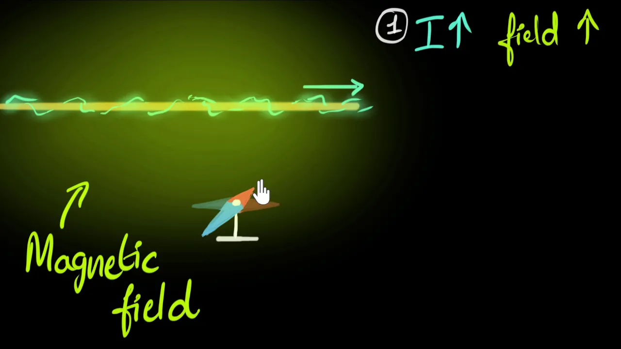
Oersted's experiment (& magnetic field due to current)
76.7K
In 1820, Danish physicist Hans Christian Oersted discovered that electric current produces a magnetic field, as demonstrated when a compass needle deflected when placed near a current-carrying wire; this experiment revealed that the magnetic field lines around a straight current-carrying wire form concentric circles centered on the wire, with the field direction depending on current direction and field strength increasing with current and decreasing with distance from the wire.
Click to watch →

1 Bio savrat law || oersted's observation || moving charge and magnetism
132.5K
Hans Christian Oersted discovered that electric current produces a magnetic field. In his experiment, he connected a battery to a wire and placed a magnetic compass nearby. When current flowed, the compass needle vibrated and deflected; when current stopped, the needle returned to its original position. This proved that moving charges create magnetic fields, similar to how permanent magnets attract iron objects. The magnetic field strength depends on the current magnitude, with higher current producing stronger fields.
Click to watch →

فيزياء تالتة ثانوي 2026🔥محاضرة (8) - الفيض المغناطيسي والمجال المغناطيسي للسلك المستقيم
102.1K
Hans Christian Oersted discovered that an electric current flowing through a wire creates a magnetic field around it. He observed that a compass needle placed near a current-carrying wire deflected, establishing the connection between electricity and magnetism.
Click to watch →

गतिमान आवेश तथा चुंबकत्व One Shot | Class 12th physics chapter 4 one shot ll | UP Board 2027
41.6K
Hans Christian Oersted discovered that when electric current flows through a conductor, it produces a magnetic field around it. In his experiment, he observed that a magnetic needle deflects when current flows through a nearby wire. This discovery established the connection between electricity and magnetism, showing that moving charges create magnetic fields.
Click to watch →
Deep Dive
Basic vector physics, particularly the concept of perpendicular directions, to prepare for Fleming's Left-Hand Rule.

Railway Technician Grade 1 | Basic Science Enginering | Magnetism Complete Theory + MCQ 🔥🔥
97.9K
Fleming's Left-Hand Rule determines the direction of force on a current-carrying conductor in a magnetic field. Stretch thumb, forefinger, and middle finger of left hand mutually perpendicular. Forefinger points in direction of magnetic field (North to South), middle finger in direction of current, and thumb shows direction of force. For positive charges, current direction is same as velocity. For negative charges, current direction is opposite to velocity. For neutral particles like neutrons, no force acts.
Click to watch →

Navy MR Physics Class 2025 | BRAHMASTRA Marathon Class | Navy MR Physics MCQs By Saurabh Sir
61.2K
Fleming's Left-Hand Rule is used to determine the direction of force on a current-carrying conductor placed in a magnetic field. The thumb, forefinger, and middle finger of the left hand are held mutually perpendicular to each other. The forefinger points in the direction of the magnetic field, the middle finger points in the direction of the current, and the thumb points in the direction of the force (motion). This rule is used in electric motors.
Click to watch →

Bihar Board Class 10th Science VVI Subjective 2025 | 10th Science Tandav Series Day 1| 10th Science
367.3K
Fleming's Left-Hand Rule states: Stretch the thumb, forefinger, and middle finger of the left hand mutually perpendicular. If the forefinger points in the direction of the magnetic field, and the middle finger points in the direction of the current, then the thumb will point in the direction of the force on the conductor. This rule determines the direction of force on a current-carrying conductor in a magnetic field.
Click to watch →

LIVE🔴 | CLASS 10TH SCIENCE-1 MAHA MARATHON | CH-1,4,6,7 10 | 10TH SCIENNC--1 BOARD EXAM 2026 |
25.1K
Fleming's Left-Hand Rule is used to find the direction of force on a current-carrying conductor placed in a magnetic field. Stretch the thumb, forefinger, and middle finger of the left hand mutually perpendicular to each other. The forefinger points in the direction of the magnetic field, the middle finger in the direction of current, and the thumb indicates the direction of force.
Click to watch →

Class 12 Physics Chapter 4 to 6 One Shot | Class 12th Physics 750 VVI Questions 2025 | Full Revision
22.4K
Fleming's Left-Hand Rule is used to determine the direction of force on a current-carrying conductor in a magnetic field. Stretch the thumb, forefinger, and middle finger of the left hand mutually perpendicular to each other. If the forefinger points in the direction of the magnetic field (B) and the middle finger points in the direction of current (I), then the thumb indicates the direction of the force (F) on the conductor.
Click to watch →
Prerequisite Knowledge
- Concept 01Basic concepts of magnetism, including magnetic poles, magnetic field lines, and magnetic flux.
- Concept 02Fundamental electrical circuit theory, specifically direct current (DC), voltage, and current flow.
- Concept 03The relationship between electricity and magnetism, specifically how flowing current generates a magnetic field (Oersted's Law).
- Concept 04Basic vector physics, particularly the concept of perpendicular directions, to prepare for Fleming's Left-Hand Rule.
Subsequent Learning
- Step 01The role and mechanics of commutators and brushes in maintaining continuous rotation in a practical brushed DC motor.
- Step 02The concept of Back Electromotive Force (Back EMF) and Lenz's Law, and how they govern motor speed and current draw.
- Step 03The difference between various types of DC motors, such as brushed, brushless (BLDC), shunt, and series-wound motors.
- Step 04The principles of electrical generators and AC motors to understand how electromagnetic induction is applied to power generation.
DC Motor Basics
Torque & Coils
DC Motor Basics
0:01Playing Section
- 1
Explains stator, armature, and collector roles.
- 2
Describes Lorentz force driving coil rotation.
- 3
Details brushes supplying current for motion.
Maxwell Stress on Rotor Teeth (The Slotted Rotor Paradox)
While textbooks typically explain DC motor operation using the Lorentz force acting directly on current-carrying copper conductors, this model does not accurately describe practical commercial motors. In real DC motors, conductors are placed inside slots within an iron rotor. Because the iron has high magnetic permeability, it channels the magnetic flux away from the slots and through the rotor's teeth. Consequently, the magnetic field inside the slots is extremely weak, and the actual Lorentz force on the copper wires is negligible. Instead, the torque is almost entirely generated by magnetic forces acting directly on the magnetized iron teeth of the rotor, a phenomenon best explained by the Maxwell Stress Tensor. The currents in the conductors merely serve to alter the magnetic field distribution, shifting the mechanical forces to the iron structure itself. This distinction is crucial for understanding practical machine design.
Deep Dive
The role and mechanics of commutators and brushes in maintaining continuous rotation in a practical brushed DC motor.

Урок 178 (осн). Рамка с током в магнитном поле. Электродвигатель
85K
A commutator consists of two semi-circular copper rings attached to the ends of the loop, connected to the power source. Brushes are stationary contacts that press against the commutator. As the loop rotates, the brushes switch connections at the right moment, reversing the current direction and allowing continuous rotation in one direction.
Click to watch →

🔥FEEE || TRANSFORMER AND MACHINE II UNIT-6 || LEC-1|| BY-RAHUL SIR
15.1K
The commutator consists of multiple copper segments insulated from each other, mounted on the armature shaft. Commutator segments are connected to armature windings. Brushes (typically carbon or graphite) maintain electrical connection between the stationary external circuit and the rotating commutator. Brushes are mounted in brush holders and press against the commutator surface. The commutator and brushes work together to enable continuous electrical contact with the rotating armature.
Click to watch →

쉼 없이 돌아가는 직류 브러시 모터의 원리
930.2K
A DC brush motor achieves continuous rotation by using a commutator (copper plates) and carbon brushes to automatically reverse the current direction in the coil whenever it reaches the horizontal position, preventing the magnetic forces from locking the rotor in place; this is solved by dividing the commutator into three separate pieces, ensuring that when power is applied, at least one piece is always in contact with the brushes, allowing continuous rotation without getting stuck.
Click to watch →

Magnetic Effects of Electric Current Class 10 Term 2 | Full Chapter | One Shot
565.6K
The commutator is a split ring that reverses the direction of current in the coil every half rotation, ensuring that the force on the coil always acts in the same direction to maintain continuous rotation. Brushes are stationary contacts that press against the rotating commutator to supply current to the coil. Without the commutator, the coil would oscillate instead of rotating continuously.
Click to watch →

DC Motor with Brushes and Commutator, Easy
281.9K
A simple DC motor consists of a rotor with wound coils, a commutator that switches current direction, brushes that maintain electrical contact, and permanent magnets; the motor operates on the principle that when current flows through a coil, it becomes an electromagnet that experiences repulsion or attraction forces from the permanent magnets, creating continuous rotational motion as the commutator periodically reverses the current direction to sustain rotation.
Click to watch →
Deep Dive
The concept of Back Electromotive Force (Back EMF) and Lenz's Law, and how they govern motor speed and current draw.

جميع كلاميات الفصل الثاني /الدور الثاني + دخول شامل
38.6K
Back EMF (counter EMF) is the voltage induced in a motor coil as it rotates in a magnetic field. According to Lenz's Law, this induced voltage opposes the applied voltage that drives the current. The magnitude of the back EMF is given by ε_back = NBAω, where N is the number of turns, B is the magnetic field strength, A is the area of the coil, and ω is the angular velocity. Back EMF is a key factor in determining the motor's speed and efficiency.
Click to watch →

back emf explained
323.2K
Back EMF (self-inductance) is an opposing voltage generated in electric motors when the rotating coil cuts through magnetic field lines, following Lenz's law; this induced EMF opposes the applied voltage, meaning the net voltage driving current equals the applied voltage minus the back EMF, which is why motor current decreases as speed increases and why sudden motor stoppage causes dangerous voltage spikes that can damage the motor.
Click to watch →
part-3 ch-12 Electromagnetic Induction class 12 science maharashtra board new syllabus Eddy current
97.6K
The induced EMF in a generator follows the formula e = E₀ sin(2πft), where E₀ is maximum EMF, f is frequency, and t is time. The frequency f represents how many complete revolutions the coil makes per second. Alternating Current (AC) continuously changes direction, while Direct Current (DC) flows in a single direction. Back EMF is the induced EMF that opposes the current flow in a generator. When current flows through the armature, it creates a magnetic field that opposes the original field. Lenz's Law states that the induced EMF always opposes the change that caused it - this is a fundamental principle of electromagnetic induction. The induced current creates a magnetic field that opposes the original change in flux. This opposition reduces the net current in the circuit and is an unavoidable natural property of electromagnetic systems.
Click to watch →

فيزياء السادس علمي || المراجعة المركزة الاقوى || جميع كلاميات الفصل الثاني وبالتفصيل
1.2M
This section covers electric motors in detail. An electric motor converts electrical energy into mechanical energy using the motor effect. When current flows through a coil in a magnetic field, a force is exerted on the coil, causing it to rotate. The back EMF is the EMF induced in the motor coil that opposes the applied voltage. The back EMF is given by ε_back = NBAω cos(ωt), and it reduces the effective voltage across the motor, limiting the current. The back EMF is a consequence of Faraday's Law and Lenz's Law, as the changing magnetic flux through the rotating coil induces an EMF that opposes the applied voltage. The motor effect is the reverse of electromagnetic induction, demonstrating the principle of conservation of energy.
Click to watch →

विद्युत चुंबकीय प्रेरण - One Shot | Class 12 Physics Chapter 6 Electromagnetic Induction | BSEB
70.8K
Lenz's Law states that induced current opposes the change in flux that produced it. This is a consequence of energy conservation. Motional EMF occurs when a conductor moves through a magnetic field, causing charge separation. The formula is ε = vBL (for perpendicular motion) or ε = vBL sin θ (for angled motion).
Click to watch →
Deep Dive
The difference between various types of DC motors, such as brushed, brushless (BLDC), shunt, and series-wound motors.
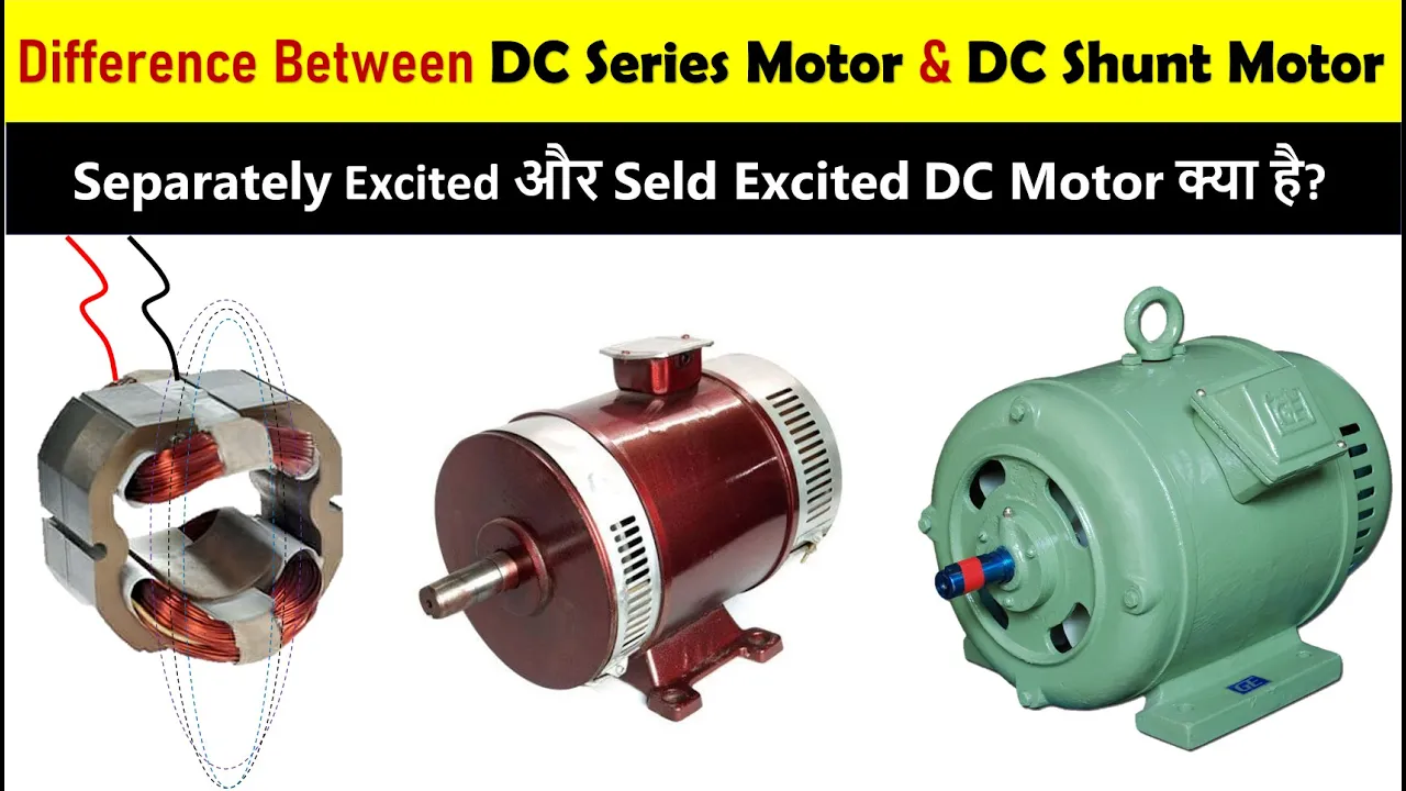
Difference Between DC Series Motor Vs Shunt Motor in Hindi | DC Motor Types | Electrical DC Motor
8.1K
DC Series Motor has field and armature windings connected in series, providing high starting torque but poor speed regulation, making it suitable for applications like electric trains and cranes; DC Shunt Motor has field and armature windings connected in parallel, offering excellent speed regulation and smooth operation, making it ideal for applications like electric lifts, fans, and blowers.
Click to watch →
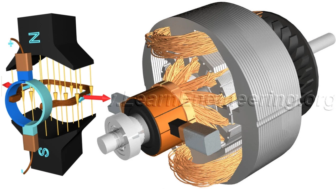
DC Motor, How it works?
8.1M
DC motors have two main constructions based on field coil connections: shunt and series motors. In series wound motors, field coils are connected in series with rotor windings, providing good starting torque but causing speed to drop drastically under load. In shunt motors, field coils are connected in parallel, resulting in low starting torque but ability to run at nearly constant speed regardless of load.
Click to watch →

DC Series vs DC Shunt motor इनमें क्या अंतर है?
52.3K
DC series motors connect armature and field windings in series, providing high starting torque but poor speed regulation due to flux saturation at high currents, making them suitable for traction and heavy-duty applications; DC shunt motors connect windings in parallel, maintaining constant field flux for superior speed regulation, making them ideal for constant-speed applications like pumps and ventilation systems.
Click to watch →
DC Motor !! Characteristics And Basics !!
112.5K
This comprehensive section covers the three main types of DC motors. DC Shunt Motors have parallel field windings, providing constant flux, linear torque-current relationship, and good speed regulation. DC Series Motors have series field windings, providing very high starting torque (T ∝ Ia²) but dangerous runaway conditions. DC Compound Motors combine both types: Cumulative Compound adds fluxes for good starting torque and speed regulation, while Differential Compound subtracts fluxes but is rarely used due to runaway risks. Key concepts include flux behavior, torque-speed relationships, and the inverse relationship between torque and speed.
Click to watch →

BE3251|BE3252|BE3254 BEEE DC Motor Construction,Working Principle,Types,Applications.#r2021 #beee
2.2K
Brushed DC motors use commutators to reverse current every half cycle, creating single-direction torque. The rotor spins 180 degrees, requiring pole flipping via carbon brushes for 360-degree rotation. Brushless DC motors eliminate brushes using electronic commutation with permanent magnets on rotor and electromagnets on stator. Characteristics: shunt motors (constant speed, medium torque, used in fans and lathes), series motors (variable speed, high torque up to 500%, used in trains), compound motors (adjustable speed, used in elevators), and brushless motors (used in electric vehicles and pumps).
Click to watch →
Deep Dive
The principles of electrical generators and AC motors to understand how electromagnetic induction is applied to power generation.

ELECTROMAGNETIC INDUCTION - 15 Most Important PYQs in 1 Shot || JEE Main
48.2K
Faraday's Law states induced EMF equals negative rate of change of magnetic flux (ε = -dΦ/dt), with Lenz's Law indicating opposition to flux change. Current is charge flow rate (I = dQ/dt). Motional EMF in moving conductors is ε = Bvl, with direction determined by Fleming's Right-Hand Rule. AC generators produce alternating EMF when coils rotate in magnetic fields: ε = NBAωsin(ωt), with maximum ε_max = NBAω and minimum zero. The time period is T = 2π/ω. These principles form the foundation for understanding electromagnetic induction and AC power generation.
Click to watch →
جميع كلاميات الفصل الثاني /الدور الثاني + دخول شامل
38.6K
This section covers practical applications of electromagnetic induction. Electric guitar pickups work on the principle of electromagnetic induction—vibrating ferromagnetic strings change the magnetic flux through a coil, inducing a current that is amplified. Induction cookers use eddy currents: a changing magnetic field induces currents in a ferromagnetic pan, generating heat directly in the pan. The section covers AC and DC generators. An AC generator consists of a rotating coil in a magnetic field with slip rings, producing alternating EMF. A DC generator uses a commutator to produce pulsating DC output. The frequency of the induced EMF depends on the rotation speed of the coil. Electric motors convert electrical energy into mechanical energy using the magnetic force on a current-carrying conductor. Back EMF (ε_back = NBAω) is the voltage induced in the motor coil as it rotates, opposing the applied voltage. The current is determined by I = (V - ε_back)/R. When the motor is first started, the back EMF is zero, so the current is maximum. As the motor speeds up, the back EMF increases, reducing the current.
Click to watch →
الامتحان الاسترشادي الثاني فبراير | فيزياء 3 ثانوي | م/ محمود غالي
189
This section covers electromagnetic induction and AC generator operation. Torque on current-carrying coil τ = NIAB sin(θ) drives electric motors. Mutual inductance M relates induced EMF to current change rate: ε = -M(dI/dt). AC generators produce sinusoidal EMF: ε = ε₀ sin(ωt), reaching half maximum at ωt = 30° or 150°. Maximum EMF ε₀ = NBAω occurs when coil is parallel to magnetic field. These principles form the basis of electrical power generation and motor operation.
Click to watch →

فيزياء الثالث متوسط | الفصل سادس المولد الكهربائي | محاضرة - 4
223.4K
Self-induction has two main applications: AC generator and DC generator. An AC generator converts mechanical energy to electrical energy using electromagnetic induction, consisting of a coil wound around an iron core, two insulated slip rings, carbon brushes, and a permanent magnet. When the coil rotates within the magnetic field, it cuts through magnetic field lines, inducing an electromotive force that generates alternating current. Alternating current (AC) changes direction periodically, alternating between positive and negative values, represented graphically as a sine wave. A DC generator uses a commutator instead of slip rings to convert AC to DC, ensuring current flows in one direction. The commutator reverses polarity at the appropriate moment during each rotation. An electric motor converts electrical energy to mechanical energy using the same components, operating on the principle of magnetic force acting on a current-carrying conductor. The commutator maintains continuous rotation by reversing current polarity. Electric motors are used in appliances like vacuum cleaners, drills, mixers, and fans.
Click to watch →

Electric Generators | Electric Motors | Mutual Induction| Holt Physics
656
Electromagnetic induction occurs when magnetic flux through a coil changes, inducing an emf. Three methods achieve this: changing magnetic field strength, moving the coil in/out of the field, or rotating the coil to change its orientation relative to the field. Generators convert mechanical energy to electrical energy by rotating coils in magnetic fields. Practical power generation uses hydroelectric plants (converting water potential energy to kinetic energy through turbines) and thermal plants (burning fuel to heat water into steam that drives turbines). As coils rotate with constant angular speed, the angle between coil normal and magnetic field continuously changes, producing sinusoidal emf variation described by e = NBAωsin(ωt). Standard systems operate at 50 Hz, with angular speed related to frequency via ω = 2πf.
Click to watch →
DC Motor Basics
Torque & Coils
DC Motor Basics
0:01- 1
Explains stator, armature, and collector roles.
- 2
Describes Lorentz force driving coil rotation.
- 3
Details brushes supplying current for motion.
Maxwell Stress on Rotor Teeth (The Slotted Rotor Paradox)
While textbooks typically explain DC motor operation using the Lorentz force acting directly on current-carrying copper conductors, this model does not accurately describe practical commercial motors. In real DC motors, conductors are placed inside slots within an iron rotor. Because the iron has high magnetic permeability, it channels the magnetic flux away from the slots and through the rotor's teeth. Consequently, the magnetic field inside the slots is extremely weak, and the actual Lorentz force on the copper wires is negligible. Instead, the torque is almost entirely generated by magnetic forces acting directly on the magnetized iron teeth of the rotor, a phenomenon best explained by the Maxwell Stress Tensor. The currents in the conductors merely serve to alter the magnetic field distribution, shifting the mechanical forces to the iron structure itself. This distinction is crucial for understanding practical machine design.
Basic concepts of magnetism, including magnetic poles, magnetic field lines, and magnetic flux.
Fundamental electrical circuit theory, specifically direct current (DC), voltage, and current flow.
The relationship between electricity and magnetism, specifically how flowing current generates a magnetic field (Oersted's Law).
Basic vector physics, particularly the concept of perpendicular directions, to prepare for Fleming's Left-Hand Rule.
The role and mechanics of commutators and brushes in maintaining continuous rotation in a practical brushed DC motor.
The concept of Back Electromotive Force (Back EMF) and Lenz's Law, and how they govern motor speed and current draw.
The difference between various types of DC motors, such as brushed, brushless (BLDC), shunt, and series-wound motors.
The principles of electrical generators and AC motors to understand how electromagnetic induction is applied to power generation.
863 views19likes3:42@JaescompanyOriginal Release: 2019-01-16
How does a DC motor work?
After talking about the history and the basic principles of electric motors After demostrating the Lorentz force principle After building a small version of a DC motor with everyday materials After having disassemble a real version of a DC motor In this video we are going to explain in detail the functioning of a DC motor Let us take the example of the most simple version of a DC motor: This is the stator which is responsible for the creation of a magnetic field.
This is the armature with a simple copper coil and represents the rotating part of this engine.
The armature receive the electric current thanks to its connection with the collector.
Like we’ve already seen in our last experiment the Lorentz force was responsible for the rotation of the tin wire The wire was immersed in a magnetic field and while the electricity flowed into it a perpendicular force acted on it letting the rotation happen Here again the Lorentz force is responsible for the rotation of the copper coil n fact when the electricity flows through the coil, an electromagnetic force acts on it These are the brushes which are able to let the electricity flows into the copper coil of our engine When the electricity flows into the coil we notice that on the left side of the coil the electricity will always flows away from us While on the right side electricity will alway flows towards us This ensures that the torque action is also in the same direction throughout the motion of the coil But in this situation the torque action is not the same during the whole rotation of the coil In fact, we can notice a slowdown of the rotation when the coil is nearly perpendicular to the magnetic field flux That’s becouse in this position the value of the tourque action is near zero By adding a second coil to the rotor the rotation will be more regular since in this way, when the first coil is in the vertical position the second coil will be connected to the power source so that the motor force will be always present in the system The presence of more coils into the rotor wil make the rotation smoother The brushes are pushed against the collector through some springs allowing the current flow to not be altered when the brushes are consuming due to their mechanical friction with the commutator
Up Next
23:01
Regenerative Braking Explained: How EVs Recharge by Slowing Down
@Jeremy_Fielding
953.3K views•2024-09-11

12:53
21cm Hyperfine Transition in Neutral Hydrogen: Radio Astronomy Basics
@AaronRobertParsons
12.4K views•2011-10-13

32:32
NMR Spin Physics I: Zeeman Effect, Resonance Condition & Larmor Frequency
@nptel-indianinstituteofsci8064
2.3K views•2024-01-17

27:14
Entropy and the Second Law of Thermodynamics Explained
@veritasium
27.5M views•2023-07-01
Related Study Plans & Knowledge Roadmaps
Structured learning paths in Physics
physics
Nuclear Physics (Decay, Fission & Reactors)
01Atomic Structure and the Binding Force
02Radioactive Decay and Half-Life
03Nuclear Fission Mechanics and Chain Reactions
+ 2 more learning modules
12h5 modules
Explore Roadmap
physics
Soft Matter (Polymers, Colloids & Rheology)
01Foundations of Soft Matter & Thermal Forces
02Polymer Physics and Macromolecules
03Colloids, Surfactants, and Self-Assembly
+ 2 more learning modules
38h5 modules
Explore Roadmap
physics
Analytical Mechanics: Lagrangian & Hamiltonian
01Mathematical Foundations: Calculus of Variations
02From Newtonian Mechanics to Constraint Dynamics
03The Principle of Least Action & Lagrangian Mechanics
+ 3 more learning modules
28h6 modules
Explore Roadmap
physics
General Relativity (Spacetime & Cosmology)
01Foundations of Relativity: Special Relativity
02The Geometry of Spacetime: Equivalence Principle & Curvature
03Einstein's Field Equations: The Mathematics of Gravity
+ 2 more learning modules
55h5 modules
Explore Roadmap