
![X-ray Interactions Photoelectric and Compton Scattering for Radiologic Technologists [Rad Physics]](https://i.ytimg.com/vi_webp/OaQHP4jD_hE/maxresdefault.webp)








![[닥튜버] 통풍치료의 육하원칙(엄완식 원장, 전재범 교수)](https://i.ytimg.com/vi/s9QUzCHuZNU/maxresdefault.jpg)


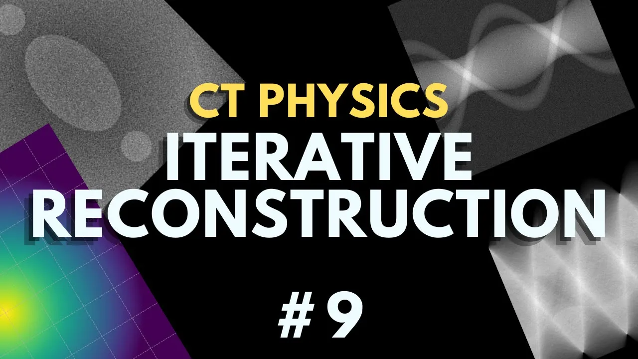

![Deep Learning CT vs Iterative Reconstruction [Evaluation CNR, Noise Texture: Nett AOCNR 2021]](https://i.ytimg.com/vi_webp/LXojNXVDqOg/maxresdefault.webp)




CT scanners use rotating x-ray tubes and detectors to acquire cross-sectional images through filtered back projection, where the linear attenuation coefficient determines tissue appearance in Hounsfield units (air = -1000, water = 0); key factors affecting image quality include slice thickness (thicker slices improve contrast but reduce spatial resolution), pitch (table movement relative to beam width), and reconstruction filters (bone filters improve spatial resolution but increase noise while soft tissue filters reduce noise but decrease resolution).
CT Physics Basics: Radiology Resident Review Guide
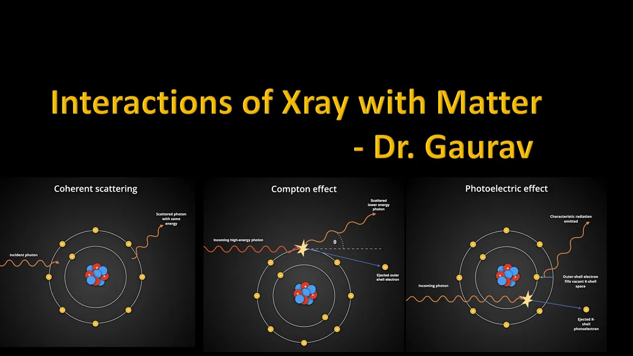
Added:Fundamental X-ray physics, including the mechanisms of X-ray production, attenuation, and the interaction of radiation with matter (photoelectric effect and Compton scattering).
Basic mathematical concepts used in medical imaging, specifically 2D and 3D coordinate systems and the concept of cross-sectional anatomy.
Fundamental principles of radiation safety, dose metrics (such as CTDI and DLP), and the ALARA (As Low As Reasonably Achievable) concept.
Advanced CT modalities, including Dual-Energy CT (DECT), Spectral CT, and Multi-Detector CT (MDCT) technology.
Advanced image reconstruction algorithms, specifically comparing Filtered Back Projection (FBP) with Iterative Reconstruction (IR) and Deep Learning-based reconstruction.
Clinical protocol optimization, learning how to adjust scan parameters (kVp, mAs, and pitch) to balance image quality and patient radiation dose.
Practical artifact troubleshooting and mitigation techniques in clinical practice, such as metal artifact reduction (MAR) algorithms.
75.3K views1.3Klikes44:54Original Release: 2021-01-06
hi this is elizabeth edney and today we're going to go over the basics of ct physics today's lecture theme is the office if you're intimidated by the physics portion of the boards you're not alone i promise to keep this lecture as simple and basic as possible hopefully this is going to be simple enough for michael scott to understand so we're going to go over four main topics and throughout the lecture i have some practice multiple choice questions you can play along with at home key terms and key concepts will also be highlighted in pink so ct scanners have four main components which we'll cover in more detail first is the x-ray tube followed by filtration devices and column meters and these sit opposite the radiation detector devices which can be individual or arranged in an array and in the center we have our patient in this case dwight schrute here's just another representation of a ct scanner again we have the x-ray tube here sitting opposite the x-ray detector here and both of these rotate around the patient then signals from the detector are sent to a computer which creates an image so let's look more closely first at the x-ray tube these follow the same basic concepts as radiographic tubes the focal spot is the portion of the anode that receives the electron beam from the cathode it's large for ct compared to say mammal where the focal spot is 0.3 to 0.6 millimeters for ct it's about one millimeter so this is this means it can tolerate a large amount of heat loading uh the anode is typically made of tungsten and some have a rotating vacuum to help dissipate heat and these are very expensive so if we zoom into the x-ray tube we can see a little bit more detail here's that anode that's made of tungsten and current flows from the cathode which is labeled as the filament in this picture to the anode as that happens energy is lost and it's dissipated as x-rays here so the anode is just a big piece of metal in this case tungsten and it has two jobs one to turn the electronic energy coming at it into radiation and two to dissipate heat how efficiently it does those jobs depends on the atomic number of the anode material and the energy of the electrons so tungsten is good because it has a high atomic number of 74 so it doesn't melt with high temperatures and it also has a low evaporation rate if we're going to compare the anode to an office character who do you think it would be obviously the anode is going to be creed because he's approximately 74 years old so there's a little mnemonic to remember the atomic number of tungsten and he's been through a lot in his life so obviously he's the most mentally and physically tough employee in the office the tube needs a large high frequency power supply and the voltage usually ranges from 80 to 140 kilovolts ma stands for milliampere which is a unit measuring the current and it's up to a thousand for ct milliamps times the seconds gives us mas and this is a unit we use to describe the current a point on a patient receives over the time that that point is in the beam depending on the scanner a full rotation takes 0.3 to 2 seconds so this concept also relates to the width of the beam and the table speed the tube axis is placed perpendicular to the imaging plane to reduce the heal effect concept that you're probably familiar with from x-ray physics so a higher anode angle will result in less of a heel effect and modern ct scanners use a slip ring technology if the machine had wires they would all get tangled as it rotates around the patient so instead the slip ring are these contacting parts that just slide over each other basically you just need to know that the slip ring eliminates wires and it improves ct performance our first practice question ct beam shaping filters or bowtie filters are often made of what aluminum copper molybdenum teflon or tin and the answer is teflon now we'll move on to the second component of a ct scanner filters the filter is circled in purple here on our graphic these are typically made of copper or aluminum aluminum and their job is to remove the low energy x-rays that would only serve to increase the patient dose this results in a very penetrating x-ray beam and it reduces beam hardening artifact which is a key concept so let's say that again filtration reduces beam hardening artifact a bowtie filter is used which will filter less in the center and more on the edges this helps compensate for the shape of a patient's head or body which is going to be more thick centrally meaning it will attenuate more of the x-rays centrally having this shaped filter makes the x-rays that end up reaching the detector side be more uniform comparing images created without a filter and with a bowtie filter show that the bow tie filter creates a more uniform image with better contrast to noise so let's review some high yield points about bow tie filters they compensate for uneven filtration they reduce scatter and they reduce dose here's another practice question ct collimation is most likely used to change x-ray beam what width intensity half value layer or iso center and the answer is width so now we're moving on to collimators the component found under the filter collimators are used to reduce scatter and they're found both at the x-ray tube side and at the detector side you can see after the beam passes through the filter the collimator is made of lead and it acts as a corset reducing the width of the x-ray beam in our modern multi-slice scanners collimators determine the beam width in a single slice scanner they determine the slice thickness but that's now determined by post-processing if we have a wider beam coming through the collimator that means we'll reduce the scan time because because that wide beam covers more area in each turn we're going to reduce motion artifact because we're reducing the scan time and we'll we'll increase partial volume averaging because that beam is more divergent and the radiation dose will be unchanged essentially the changes cancel out because it's a wider beam but decreased scan time and unchanged current our final component of the ct scanner is radiation detectors each detector measures the radiation transmitted through one ray detectors are typically devices called scintillators which make light when they get hit by an x-ray they're then coupled to light detectors called photomultiplier tubes and photodiodes in the picture you can see x-rays hit the scintillator get converted into light that hits the light detector and then gets converted into energy these detectors respond quickly and are highly efficient after the photomultiplier tube converts the light to energy all you need to know is that what we call computer magic happens the computer takes that energy which is an electronic signal proportional to the incident radiation and converts it to a grayscale picture pixel these are some common materials radiation detectors are made from cadmium tongue state cesium iodide calcium fluoride or bismuth germinate another picture showing the photon hitting the scintillator and getting converted into light to adjust the slice width you have to adjust detector width obviously we're not going to manually change the machine parts every time we want to change slice thickness but we can effectively add or subtract adjacent detectors for example if we have a 1.25 millimeter wide detector we can combine every two detectors together to get 2.5 millimeter slices it makes sense then that the minimum slice thickness is determined by detector width which is a high yield point minimal slice thickness is determined by detector element aperture width in a modern ct here's another view of our tube sending x-rays through a patient here's the patient which then have different energies when they reach the detector this profile line here shows how the rays in the center which might have to go through multiple thick layers of bone in the skull for example usually have a lower energy hitting the detectors than the rays in the periphery so that covers our first portion of ct hardware next we're going to talk more about how the image that we read is acquired and processed this is the point in the lecture where we normally watch a couple of funny videos but since we're doing this virtually i suggest you go give your brain a five minute break walk around and then come back for our next topics okay so we're back with old single detector cts one slice was generated every 360 degree turn now with multi-detector cts there are more detector arrays that allow us to acquire multiple slices per 360 degree turn for a 64 slice ct 64 slices are obtained per rotation these thin slices allow us to create multi-planar reformats and have high temporal resolution which is the ability to see image detail in the smallest window of time the total number of individual detector elements for a 64-row scanner is most likely what sixty-four by one by eight one hundred eight hundred or 10 000.
the best answer is number four they range from about 650 to 800-ish elements per row remember that with a single detector the beam width equal the slice width or b equals s in this picture with a multi-detector array these combinations of detectors equal multiple slices and we can manipulate the slice with by combining them in different ways so to to acquire an image we have a certain size beam of x-rays passing through the patient for abdominal imaging that beam is typically around 50 centimeters a ray is a measure of the total x-ray attenuation along a line from the focal point to a single detector each detector detects one ray an important concept is that these x-rays and ct are highly filtered and have a high kv their average energy is 75 kev so ct x-rays are highly filtered high kb the intensity of the ray depends on how much of the beam was attenuated or absorbed by tissues in the patient you can see in the picture an x-ray passing through mostly lung tissue which is essentially air is going to have a lot more energy left over than an x-ray that passes through the sternum and the vertebral body a projection is all the rays at a given x-ray tube angle or a series of rays that pass through the patient at the same orientation a 64-slice ct means that 64 projections are created per tube location the beam width would equal the number of slices the slight times the slice thickness so for a 64 slice scanner that might be 64 times 0.6 millimeters giving us a beam width of about 40 millimeters we obtained multiple projections per turn of the ct machine up to 1000 the linear attenuation coefficient or lac is a measurement of how well x-rays move through a given tissue if we plot all of our raw projection data they form a sonogram like this the computer uses a process called back projection to make images by determining the linear attenuation coefficient for each pixel i realize that whole process can kind of make your head hurt just thinking about it basically we have to understand the general concept and realize that the computer is just doing a lot of math so here's a simplified example say we have this four square problem where we want to solve for a b c and d this is like a 4 pixel image we know that the sum of a and c is 6 here and the sum of b and d is 8 and so on this is like how we know the value of a projection after it passes through the patient the same way we can figure out that a equals 2 and b equals 5 the computer can figure out that a should be a white pixel for bone and b should be a black pixel for lung for example this is essentially the computer magic that i referred to earlier where the computer makes an image by manipulating that synogram data this youtube video here has a nice demonstration of the process over minutes 12 to 14 which i recommend watching here's another question in ct the kernel used refers to the amount of filtration the specific kvma setup the mathematical reconstruction filter the mascot of kentucky fried chicken or something you'd buy from a boy scout the answer is the mathematical reconstruction filter another question use of a bone filter as opposed to a soft tissue filter for reconstruction would improve what contrast scatter rejection noise spatial resolution or bits and bytes data storage and the answer is spatial resolution using the process that we just described the result is a blurry picture so the data are convoluted with a mathematical filter or a kernel to remove the blur this is called filtered back projection here's where we want to introduce the concept of spatial resolution which is the ability to distinguish small objects that are close together line pairs per centimeter illustrate the concept of spatial resolution on the top row here it's fairly easy to see that each line is separate from the next because this represents 6 pixels per line pair on the bottom row down here it's very hard to distinguish each individual line because they're so they're much lower pixels per line pair 2.05 and cts have different filters for different purposes which we've all seen doing imaging bone or soft tissue are two of the most common and these filters trade off spatial resolution for noise for example a bone filter provides very high resolution but lots of noise resolution or noise is the ability to distinguish small differences in object density from its surroundings here's an example this image has been created with a bone filter we see good spatial resolution and you can see all of the trabecular detail in the bone but we see lots of noise if you're going to draw a pencil around the border of the pectoralis muscle for example it's hard because the edges aren't very crisp it's tough to tell a difference in the density of that fat muscle interface now here's the flip side where we have an image created with a soft tissue filter the image on screen left has great contrast resolution aka very little noise we can clearly draw a pencil around the borders of the left kidney here and that soft tissue and fat interface is very crisp but the spatial resolution is poor when we change the window level settings to look at bone you really don't see that trabecular detail like we did on the previous slide that brings me to an aside don't confuse filters with windows the filter is something that our tech supply on the machine side the window and level settings are something that we manipulate at the pack station so for a chest ct we usually get soft tissue long and bone filtered images and we can change the window level settings on each one of those series but that's just manipulating the gray scale of the image not the resolution so don't confuse filters with windows newer cts use a process called iterative reconstruction rather than filtered back projection and it's not important to know the details of this but just know that iterative reconstruction can correct for noise and allows us to use a lower dose iterative reconstruction is a more modern technique allowing for lower dose basically a ct image is thus a map of linear attenuation coefficients so these are given a number called hounsfield units and it's just based on an arbitrary definition of air as -1000 and water is zero it's important to know that hounsfield units are approximate and they can vary depending on the scanner the kv and the filtration that are used here's a chart showing different house field units so water is zero fat is usually the low negative numbers bone is up to a thousand for example okay pixel size and ct is which of the following field of view over matrix size matrix over field of view two times the field of view over pitch or two times voxel size the answer is field of view over matrix size field of view is the area scanned typically for the head it's around 250 millimeters for the body around 500 millimeters and the matrix that we use is usually 512 by 512 that's the number of pixels per image so pixel size is the field of view over the matrix for example if we have a 500 millimeter field of view we divide that by our matrix which is 512 and get 0.98 you can improve spatial resolution by making the pixels smaller and you can do that by either decreasing the field of view or increasing the matrix typically for ct we deal with 0.3 to 0.8 millimeter pixels for a given slice thickness a voxel and a pixel have the same width and height a voxel is like a cube it has a third dimension shown here whereas a pixel is like a box it's just 2d and that is the average attenuation of a voxel so here in the voxel you can see different grayscale values and in this 2d pixel you see the average grayscale value value on rct images we usually look at two and a half to five millimeter slices and pixels have over four thousand shades of gray so our window width and level affect the image display by assigning a given hounsfield unit number given brightness levels a way to remember this is level starts with an l and that's what you're looking at so the typical level is going to be about the average number of hounsfield units for what you're looking at so for the abdomen say a liver if you drew a houndsfield unit roi over the liver you'd probably get somewhere around 60. so our window level setting for an abdomen is 60 and 150.
the width is the range of what you can see uh so when we're looking at a lung we're seeing air we're seeing bone we're seeing a much wider range of houndsfield units so our window number is going to be the highest 1500 approximately there's a reminder of our different hounsfield units for different densities uh go over quickly ct scanner generations the first generation ct scanners were translate rotate that meant they had one x-ray beam and one detector and they just moved one degree at a time until 180 degrees were covered it took a very long time to perform a ct about four and a half minutes just for a head and it took too long to image the chest or the abdomen the second generation scanners introduced fan beam and multi-detectors and these added three detectors one degree apart so they could rotate three degrees at a time it reasons then this cut down the scan time by a factor of three and eventually about 53 detectors were added so they could start to image the trunk third generation scanners use rotate rotate technology which we currently use and had a wider beam with over 700 detectors fourth generation are used for research they're cost prohibitive to use in clinical settings but the source rotates while the detectors stay stationary in this youtube video uh at these different time points explains a little bit more about generation scanners if you're interested okay so a review of our last 74 slides uh is that the ct fires off x-rays as it spins the table moves the patient through the detectors which are highly efficient have a lot of information that looks like a wavy mess called a synogram then a bunch of math happens filtered back projection or iterative reconstruction and we get a picture so just kind of keep that big picture in mind that's what we've learned so far that's how we get our ct image our next topic is ct techniques and here's a question in multi-detector helical ct scanning the detector pitch one is the table movements per 360 degree rotation divided by detector width two is the table movement per 360 degree rotation divided by the column meter width at isocenter 3 has a typical value of 2 to 3 for clinical use or 4 is associated with partial scanning for values less than 1.
our answer is two it's the table movement per 360 degree rotation divided by the collimator width at iso center and pitch is an important concept so we'll talk more about that all modern scanners are helical and pitch has to deal with the relationship between patient movement and tube rotation for modern cts pitch equals the table movement per rotation over x-ray beam width remember we've already learned that beam width is the same as collimator width so if the pitch is 1 that means that beam width is equal to the distance the table moves in one revolution i like this picture and screen right for showing the concept of pitch you see if pitch equals one like in this top picture there's no gap in the parts of the patient's body that are image if pitch is two like the middle picture that means the beam width is smaller than the rate of table movement so there's gaps like this and what we're imaging if the pitch is 0.5 that means there's overlap in what's being imaged or the table speed is less than the beam width here's a practice question the table movement is 12 millimeters per tube rotation and the beam width is eight millimeters what is the pitch so the answer is one point five twelve divided by eight increasing the pitch will increase scan time and radiation dose increase resolution decrease scan time and radiation dose both two and three or both one and two i'll give you a second to think it will decrease scan time and radiation dose as you might realize by now a low pitch value anything less than one will give us very good spatial resolution but at the expense of high radiation dose another concept we'll cover quickly is dual source ct these have two tubes or x-ray sources which may operate at different kvs this allows faster data acquisition and it can provide a lower dose we can also create virtual non-contrast images by having one kb near the k edge of iodine and subtracting it from the other let's look at that the 80 kev image here is noisier because fewer x-rays are penetrating the body but it has higher contrast because kd 80 kev is closer to the k edge of iodine if we average those two together they make a composite image that's closer to what we're used to seeing with a kev of around 120.
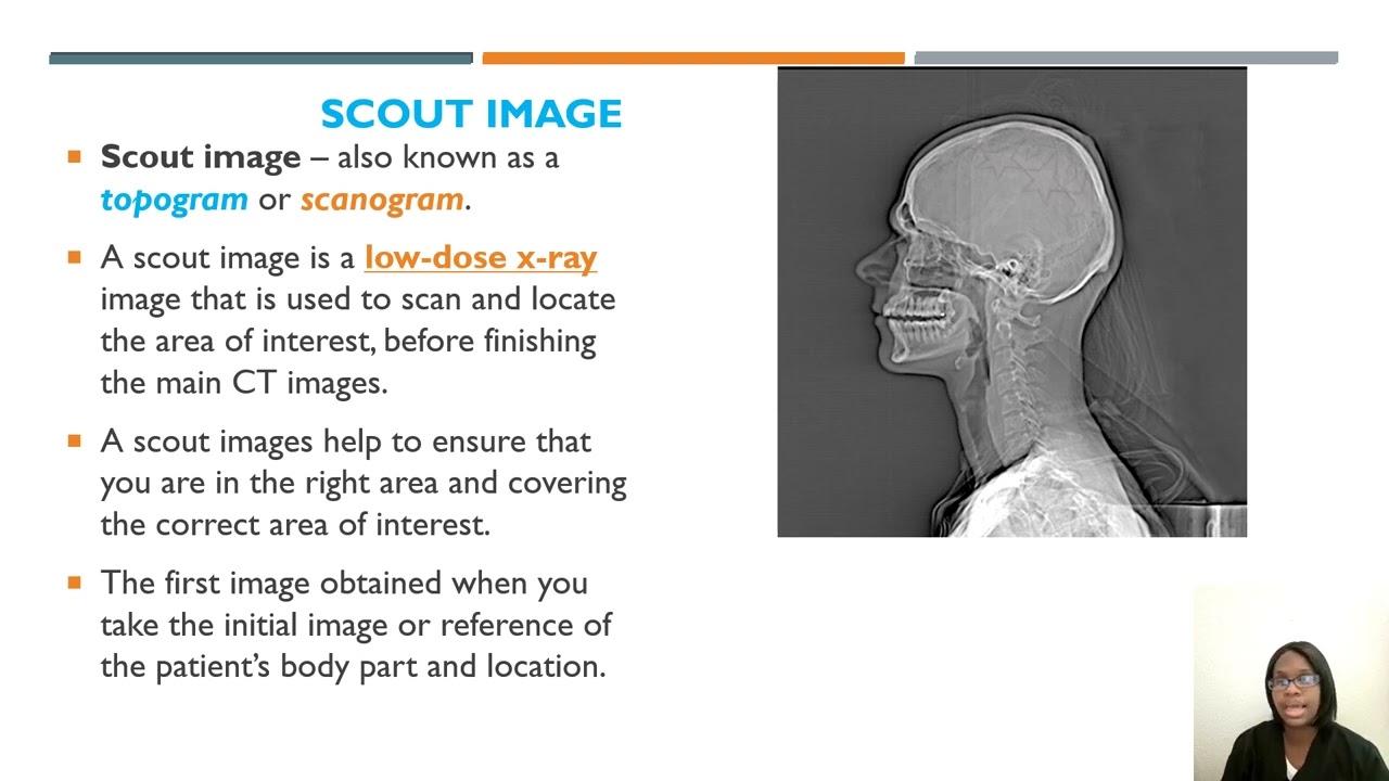
we can also do stone composition analysis which and this whole process has lots of implications for clinical use think about how we could do all of our er protocols with contrast but then if you see an incidental adrenal nodule that's indeterminate you don't need to follow it up with the adrenal protocol scan you just look at the virtual non-contrast and you can you know potentially diagnose it as an adenoma or multi-phase exams like an endograph follow-up can just be done as a single phase we can also potentially salvage pulmonary embolism studies that have bad bolus timing so we're manipulating the image based on these two different acquisitions we can get a bone-only image for example virtual non-contrast like we talked about or we can do these iodine overlays ct common techniques first we do a scout which is a radiograph that determines the area that we're going to scan and the tube current modulation you or the technologist picks the kv and the mas kvs typically range between 80 and 140 and then tube current modulation is a technique used by the scanner so the ma is automatically adjusted based on the patient thickness to reduce the dose if we had a fixed ma shown by this red line the dose would hardly ever be correct for the area of the body that we're scanning the scout image allows the machine to guess more closely in appropriate current level so if we have an area that has lots of bone lots of dense stuff tissue the machine is going to know to automatically apply a higher current to penetrate all of that whereas when we have an area that's less dense more lung or more air the machine knows from that scout radiograph that it doesn't need as much current to penetrate that portion of the body gated ct is another technique most often used for cardiac imaging the heart is always beating hopefully but it's most still in diastole so that's our best time to image the heart from a ct standpoint we can track the cardiac cycle with an ekg and then prospectively set the machine to scan in diastole as shown here this is also called the step and shoot method this gives us a relatively lower radiation dose but it doesn't provide functional information another method is retrospective gating where the machine scans for the entire cardiac cycle and then it back calculates when diastole was and creates images from the information acquired during that time shown here retrospective gating has a very low pitch and a high dose so if the tech is asking you to protocol a scan do you want it gated you might not want to choose that method if for example it's a trauma scan on a very young patient because we know it's going to have a much higher dose during ct fluoroscopy the tube is cur continuously rotating and that gives us multiple images per second which helps with procedural applications ct fluoroscopy best minimizes radiation exposure by reducing which of the following beam filtration focus size tube current slice thickness or matrix size tube current is the answer so in ct fluoroscopy we're not necessarily trying to give the highest resolution images so the tube current can be lower and that greatly reduces the dose this image shows radiation-induced alopecia caused by repeated ct angioscans which were performed over a limited section of the head and this patient who had a ruptured acom aneurysm we know from protocoling studies that different types of scans use different contrast timing our routine body scans for example have a fixed delay with the scan occurring about 65 to 70 seconds after the intravenous injection arterial phase studies might use more dense contrast and a faster rate of injection saline chasers are used to push the contrast from the tubing and the peripheral veins further into the central veins which can help reduce the total contrast volume that's given can increase peak attenuation and can reduce streak artifact one method for setting the scan timing is to select a target location from our scout shown here and then inject a small test bolus of 15-20 milliliters of contrast a low-dose scan is performed right at that location that we specified from the scout an roi is drawn in a target structure shown here like at the aortic root and then the time it takes for that structure to reach its peak attenuation is plotted in a curve shown here bolus triggering is similar in that an roi is placed in the structure of interest but the full contrast dose is injected right away and the roi and the target structure is continuous continuously monitored then when it reaches the desired threshold of attenuation the scan will start each method has its pros and cons which you can pause and read through this slide here if you're interested our last section is artifacts and i have a couple memes for our mini mental break before we finish up when the ct techs call you with a question about scan technique you might feel like michael scott in this scene these are the four phases of an overnight shift this is how i feel some days on the ultrasound rotation okay so this section in my experience is high yield material for boards question one way they seem to like to ask questions is by comparing different modality modalities or asking how changing one aspect of a scan will affect another so comparing ct to digital radiograph ct has better contrast has worse resolution has larger pixels and larger dose conversely radiographs have worse contrast resolution a worse contrast sorry better resolution smaller pixels and lower dose this is more high yield material we have a list here of factors that affect spatial resolution and factors that affect contrast resolution and i'll go in more depth for some of these so first let's talk about detector width a smaller detector will help will improve spatial resolution and here's a visual example remember slice thickness is directly correlated to detector width this tibial plateau is fractured and the fracture appears more distinct in the image at screen left which is a 1.25 millimeter slice versus the five millimeter slice as green right now let's look at the reconstruction filter for example a bone filter will give us higher spatial resolution the right rib fracture shown by the red arrow and the spinous process fracture shown by the green arrow are much more distinct in this bone filter image than the soft tissue filter on the right moving on to factors affecting contrast resolution the first thing is what i think of as just the number of x-rays this can be manipulated by changing current the kv or the pitch basically anything that increases the radiation dose will give you better contrast resolution here's an example showing that contrast improves as current increases these are four phantom images of low contrast objects a this first one is performed at 800 mas b at 400 mas c at 200 and d at 100 the visibility of the objects improves with the higher current you can see these small dots for example are visible in the higher current image and you'd really be kind of hard-pressed to see them in this lowest current image especially the even smaller ones down here whereas they're visible to us in the high current image if we have an image that's too noisy like this one at the farthest right d which i should label here that's usually caused by too few x-rays aka too low of a dose or too much soft tissue slice thickness also affects contrast resolution the thicker the slice the more x-rays we have essentially and the less noise here are those low contrast objects again but a is a thick five millimeter slice b is 2.5 millimeter c is 1.25 millimeter and d is 0.625 millimeter so the thick five millimeter slices have better contrast resolution again we can see those low contrast uh objects much better than we can in the 0.6 millimeter slice changing slice thickness will cause important trade-offs if no other parameters are changed the number of detected x-ray photons will increase linearly with slice thickness which is important so if we go from a one millimeter to three millimeter thicker slices the number of detected photons will triple and the signal-to-noise ratio increases by the square root of three or seventy-three percent if we change from 5 millimeter to 10 millimeter slices the number of detected photons doubles and the signal to noise increases by about 41 because the square root of 2 is 1.41 these kinds of changes also lend themselves nicely to test questions as far as the trade-off though a thicker slice will decrease spatial resolution in the slice thickness dimension conversely thin slices improve spatial resolution in the slice thickness dimension and reduce partial volume averaging when a thin slice exam is performed usually the current is increased to compensate for the loss of x-rays an artifact in ct is any systemic discrepancy between the ct numbers in the reconstructed image and the true attenuation coefficient of an object ct images are prone to artifacts because of the vast number of independent measurements that need to be processed in order to produce an image the first artifact that we'll cover is partial volume averaging this occurs when you have a dense thing next to a non-dense thing and the computer averages the two together this is most often seen in small lesions less than a centimeter in size the fix is to make thinner slices these will be noisier but you can acquire thinner slices and then add them together motion is an artifact that we're all pretty familiar with and the fix for motion is usually just to repeat the scan or you could get a faster scanner beep hardening occurs in high density areas commonly like here at the level of the temporal bones and this is related to preferential absorption of low energy photons creating a hardened beam of high energy photons so you get the center of the image appearing darker than the periphery because the x-rays go through the middle that go through the middle are hardened more than the ones that go through the periphery you also see these dark and like light streaks when there are two dense objects the x-rays that go through both of them are more attenuated than those that pass through one so decreasing slice thickness or increasing filtration can also help with this star or metal artifact occurs when you have a high density material like metal that attenuates everything and that creates a problem with the math during the filtered back projection potential fixes are to remove the metal you could angle the gantry or use metal reduction software out of feel artifact uh is caused by things outside the field that still attenuate x-rays and that messes with the computer's math as well these are often related to a body part like the arm which obstruct detectors and harden the beam so the fix is to move those objects the artifact shown here is caused by which of the following beam hardening metallic implant a faulty detector patient motion or scattered x-rays the answer is a faulty detector and this is a pretty commonly asked board question on practice bank sets the ring artifact is caused by one or more faulty detectors seen as a ring and it can be a calibration problem our fix is to call a service representative or to who can recalibrate the detector in ct if kv and mas are kept the same increasing slice thickness does what decrease image contrast increase spatial resolution decrease noise or reduce partial volume [Music] averaging answer is three decreases noise photon starvation artifact is caused by high attenuating areas classically the shoulders or a large patient we have an example from the office here which results in photon starvation and it looks like streaking on the image we can fix photon starvation artifact with automatic tube current modulation which will increase that dose through the thick area essentially adding photons to penetrate filtration methods can also smooth the data here's an example like we've all seen from patients that barely fit in the scanner there just aren't enough photons to penetrate the patient's body habitus when compared to radiography ct has what superior spatial resolution and image contrast inferior spatial resolution and image contrast superior resolution but inferior contrast or inferior resolution but superior contrast the answer is inferior resolution but superior contrast so that wraps up ct physics for today thank you if you made it this far and i wish you all the best of luck on radiology boards
Up Next
34:50
How Microwave Ovens Work: The Science of Heating Food
@MathAndScience
134K views•2025-11-18
6:05
Radiation Units Explained: Gray, Sievert, and More
@SciShow
342.1K views•2019-09-12

32:32
NMR Spin Physics I: Zeeman Effect, Resonance Condition & Larmor Frequency
@nptel-indianinstituteofsci8064
2.3K views•2024-01-17

27:14
Entropy and the Second Law of Thermodynamics Explained
@veritasium
27.5M views•2023-07-01
Related Study Plans & Knowledge Roadmaps
Structured learning paths in Physics
physics
Medical Physics: Imaging, MRI & Radiotherapy
01Foundations of Radiation and Matter Interaction
02X-Ray Imaging and Computed Tomography (CT)
03Magnetic Resonance Imaging (MRI) Physics
+ 3 more learning modules
15h6 modules
Explore Roadmap
physics
Nuclear Physics (Decay, Fission & Reactors)
01Atomic Structure and the Binding Force
02Radioactive Decay and Half-Life
03Nuclear Fission Mechanics and Chain Reactions
+ 2 more learning modules
12h5 modules
Explore Roadmap
physics
Soft Matter (Polymers, Colloids & Rheology)
01Foundations of Soft Matter & Thermal Forces
02Polymer Physics and Macromolecules
03Colloids, Surfactants, and Self-Assembly
+ 2 more learning modules
38h5 modules
Explore Roadmap
physics
Analytical Mechanics: Lagrangian & Hamiltonian
01Mathematical Foundations: Calculus of Variations
02From Newtonian Mechanics to Constraint Dynamics
03The Principle of Least Action & Lagrangian Mechanics
+ 3 more learning modules
28h6 modules
Explore Roadmap