








![🥇 Te enseño cómo funcionan los mosfet [PASO A PASO] 🥇](https://i.ytimg.com/vi/a6Ua6xrrrKM/maxresdefault.jpg)























![Kłopotliwe ciepło [RS Elektronika] # 25](https://i.ytimg.com/vi_webp/ko9xLmW0yn4/maxresdefault.webp)
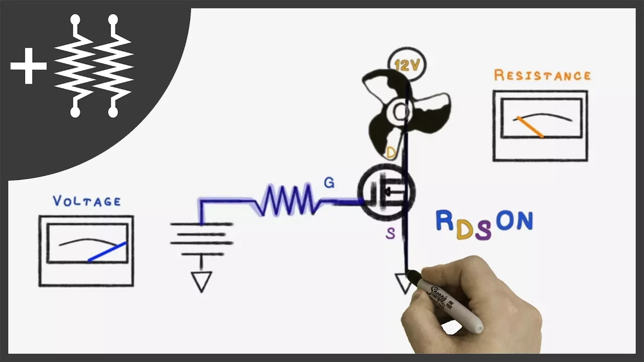
This tutorial demonstrates how to control a DC motor using an Arduino by interfacing through an N-channel MOSFET (IRF7400) and Pulse Width Modulation (PWM). The MOSFET acts as an electronic switch, with its gate connected to Arduino pin 3 (a PWM output), drain connected to the motor, and source connected to ground. The motor's other terminal connects to the positive battery terminal. PWM values from 0-255 control motor speed, where 255 provides maximum power and 0 provides none. The tutorial shows how to modify the Arduino blink program to control motor speed, demonstrating that values below 80 may not start the motor due to insufficient power. This setup enables variable speed control, automatic fading effects, and can be extended to use analog inputs like potentiometers for user-controlled speed adjustment.
Arduino Motor Control Using MOSFETs and PWM: Complete Guide
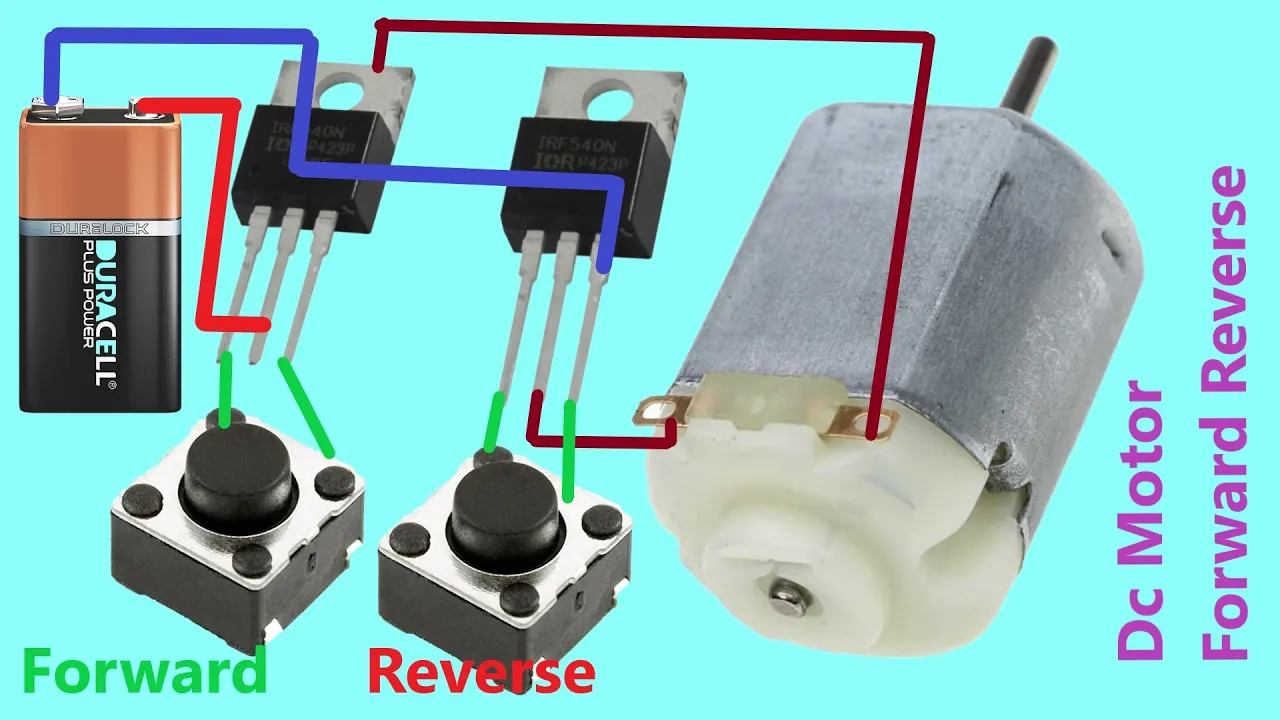
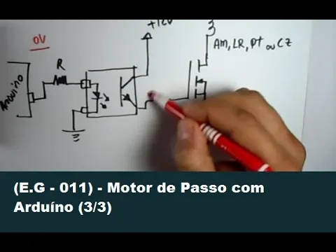
Added:okay we want to control this motor right here um and uh it's just a small motor with a gear Trin on it I'm going to hook it up to a 9volt battery um want to control that using an Arduino and so we're going to look at what you need to do to make that happen for one thing you cannot drive the motor directly from the Arduino we have to use an intermediate switching device to do that and the device we're going to use is a mosfet an inchannel mosfet at 2 in 7000 first thing you're going to want to do when you go to use a device like this is you want to look at the specification sheet and so the device itself is right here and the pin out on the device this one's actually showing the device turned around and it's showing us our pins here I'm going to spread these pins out and so with the device pointed down the pin out is Source gate drain if we flip it around so I usually like to have a drawing where the flat side is facing me and if we do that it's Source gate drain so I've got a little drawing here this is what we're going to wire up and this is the symbol for the mosfet um the gate is going to go to pin three the reason we're using pin three here is pin 3 is a pwm output on the Arduino the pwm outputs are the ones that all have the little Tilda next to them the little wiggly line next to them those are all pwm outputs so we're going to use number three and we're going to apply our signal to the gate we're going to hook our drain of the device to the motor which is going to go to our positive terminal of our battery and I originally was going to make this for a 12vt system which it could be run on U but we'll just use a 9volt battery for now to make things a little bit more portable um the source of the mosfet is going to go to ground and the ground of the Arduino and this separate system have to be common that allows us to drive the the mosfet we have to have a complete circuit and we do we're driving the gate but we have to drive a signal between the gate and the source so the source has to be connected to the common of the Arduino and we're controlling a current between the source the drain the motor and the 9volt battery so this is what we're we're shooting for since we're going to run the Arduino off of the USB we don't really need to hook up the positive 5 volts but for the ground we're going to have to take our ground and jumper over from the ground on the Arduino to ground on our board we're going to make this part of our board ground and that takes care of this connection right here well not yet but it takes care of the connection up to this point because we're going to take the source of our device and also hook it to ground so I'm going to use another green wire to do that so we can kind of follow the color code here so there's my source remember looking at the device the pin out was Source gate Source gate drain if you flip the device over facing you so pin one is the source pin number two is the gate and pin number three is the drain so so pin one is our source I've got that hooked to ground actually I don't have it hooked to ground yet it's right there so now it's hooked to ground so that takes care of the connection from our source to the Arduino ground the next thing we want to do is hook up pin three of the Arduino which is going to be the pin we drive it with we're going to take pin three and we're going to hook it to the gate so I've left a little bit of space behind the transistor to hook up the gate so pin number two on the device here is hooked to the gate of the Arduino that takes care of this connection right here now we're going to take our motor from the drain of the device okay so the drain is going to take we're going to hook it to our motor and I just happen to have the motor happen to have happens to have a nice little plugin capability so that makes things a little easier um the other side of the motor is going to go to the positive side of our power supply I'm going to take battery off temporarily here so we've hooked the drain to the motor down here we hooked the other side of the motor to v+ on our 9volt battery the only thing left to do is to hook the negative terminal of our battery to our ground that we set up our common um common and ground are pretty much used interchangeably in electronics here so that takes care of this connection here between the negative side of the 9volt battery and this common ground it's common because we have these three connections the mosfet Source the ground from the Arduino and the negative part of the 9vt battery all going to this common point we need that to make this function now the first thing you're going to want to do to test something like this is just write some simple code for it so I'm going to write a very simple piece of code for this okay I wrote some code here um and basically what I did is I just took the blink program and I modified it the uh the LED equals 3 command um I just changed that from 13 what it was before to three because we're driving this through pwm Port 3 uh in the setup we still have pin mode LED output um in the loop I've taken out the digital rights and replaced them with one analog right because this is a command we have to use for pwm we're doing an analog write which means we're writing a number from0 to 255 255 being the highest and zero being the lowest 255 means that the motor is essentially on all the time and zero means it would be off so we're this analog right command actually means we're writing to pin three and we're writing a value of 255 which means that the pulse is most of the time on it's essentially 100% on versus if we made it zero being zero percent on running the code downloading the code this way I get so I'm going to hit download you can see the the code downloading or uploading actually to the Arduino okay so running the code for 255 I get the motor spinning like this it's good to find something to put the motor in so it's upright and it doesn't um sort of roll around on the table so this is the speed for 255 now we're going to change the code to another number okay so now I'm changing the number to a lower number and I found that if you run it uh less than about 80 the motor has a hard time getting started there's too little power going to it so we're going to run it at 80 change the number down to 80 and see what happens here I'm going to download the this code and you'll probably hear the motor slowing down and I'll pan over to it here when we get done doing this so now it's running quite a bit slower so here's the motor running at a pwm value of 80 now once you've got something like this written some simple code that test it it opens the door for all kinds of possibilities you can make the speed vary up and down you could use the fade command the fade LED command to make the motor speed up and slow down automatically another thing you can do with this is use an analog input to control the speed of the motor so if you were to take a input signal from a potentiometer for instance and you could vary that voltage from the potentiometer between 0 and 5 volts then you could drive the motor from minimum speed to maximum speed what you have to keep in mind though when you do an analog read is analog read signals vary between Zer and 1023 but the analog right command goes from 0 to 255 so you have to scale down the input reading from your analog input to fit into a analog right command so usually if you divide that by four that'll give you what you need to make that work so I'll leave it to everybody to figure out some more things I can do with this
Up Next

Build a Raspberry Pi Powered Smart Bartender: DIY Engineering
@hackershack
991.2K views•2018-04-29

Triumph of Orthodoxy Icon: Byzantine Art & History Explained
@BenCallan
2.1K views•2024-08-06

FastAPI vs Flask vs Django: Choosing the Right Python Web Framework
@TechWithTim
302.5K views•2024-05-26

Game of Thrones Opening Credits: A Cinematic Analysis
@gameofthrones
46.3M views•2011-04-18
Related Study Plans & Knowledge Roadmaps
Structured learning paths in General & Interdisciplinary Studies