

















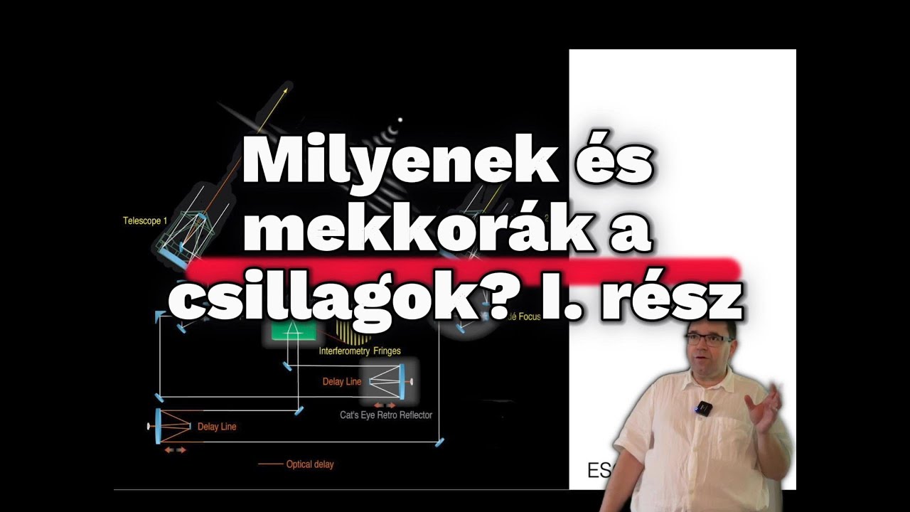

A two-telescope optical interferometer combines light from two widely separated telescopes to achieve higher angular resolution; the system requires placing the focal station at the exact midpoint between telescopes to ensure equal light path lengths, but must incorporate delay lines (long tunnels with moving trolleys) to compensate for optical path differences caused by Earth's rotation and target tracking, maintaining coherence within nanometer precision while accommodating rapid movements up to 50 cm/second.
Two-Telescope Optical Interferometer Architecture Explained
Added:Wave optics fundamentals, specifically spatial and temporal coherence, wavefronts, and constructive/destructive interference.
Basic astronomical telescope optics, including light collection, collimation, and the concept of angular resolution limit (Rayleigh criterion).
The concept of Optical Path Difference (OPD) and how path length differences affect the phase of combining light waves.
Geometric principles of astronomical observation, such as how a star's position in the sky relates to the physical baseline between two ground stations.
Aperture synthesis and multi-telescope interferometry (3 or more telescopes) for reconstructing detailed 2D astronomical images using closure phase.
Fringe tracking technology and active delay line control systems used to compensate for atmospheric turbulence (seeing) in real-time.
Data reduction in optical interferometry, specifically analyzing visibility curves to measure stellar diameters, binary star orbits, and circumstellar disks.
Case studies of major optical/infrared interferometric facilities, such as the VLTI (Very Large Telescope Interferometer) and the CHARA Array.
12.1K views214likes10:16Original Release: 2017-06-23
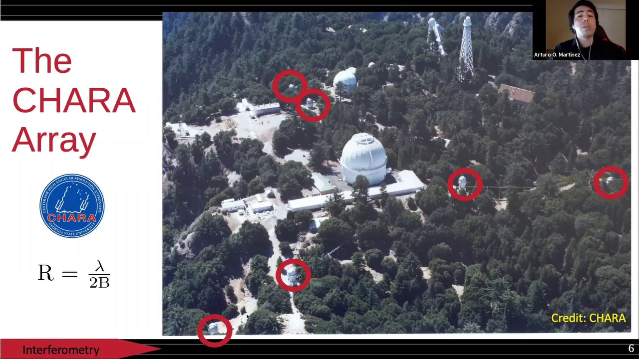
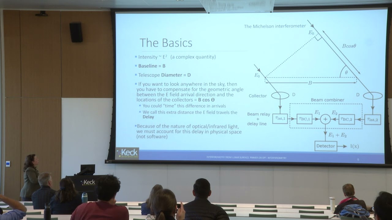
from a piece of Optics as small as this one to a primary mural as large as the polymer Hil telescope and it's 200 in or 5 m diameter telescopes maker in general do spend a lot of energy to provide and maintain optic optimal surface quality for the Optics that are used in imaging astronomy in fact if you look at most specific spefications for the Optics that are used in everyday astronomy you realize that the optical surface quality the the typical error the roughness errors on the surface of the Optics is typically somewhere between Lambda over 10 to land over 100 that means that the typical errors are smaller than a tenth of the wavelength or even 100 of the wavelength um in the most demanding cases now if you compare that to the requirement we've set in order to be able to witness interferences um the constraint that was imposed by the coherence length you realize that the optical quality of most telescopes is orders of magnitude better than this coherence length requirement that we've uh said earlier and so it is no surprise that early day astronomers uh were able to produce interference fringes by simply using a telescope an aperture mask by design a telescope is going to guarantee equal path traveled uh from the surface of the primary from the Star itself all the way down to the detector and if you put an aperture mask in front of your telescope you are going to be able to observe interference fringes there now it becomes a little trickier when you think about trying to achieve the same thing using two separate telescopes so here I labeled uh T1 and T2 my two telescopes that are separated by a pretty large distance that we're going to call the Basel line um B12 that can be several times or several tens or hundreds of times the size of the telescope the the diameter of the telescope itself you know a few hundreds of meters how would you proceed um the most sensible thing in order to witness to observe inter ference fringes uh would be to put your focal station the instrument that is going to collect right from the two telescopes at the exact halfway point between the telescopes um you do that so as to ensure that the light path that is traveled by the Light along the two interferometric arms is such that the light on the two arms reaches the detector at the exact same time um to within the coherence time of course and if you do so you're going to be able to observe your interference fringes now we're going to um use a lot more Optics than just the Optics of the telescopes themselves in order to send the light from the telescopes to the focal station and we refer to these Optics as beam Transportation Optics or BTU for short and another special place is of course going to be in the system defal lab it's self which we're going to cover in a bit more details in a later section but if you do um put your focal station and the exact halfway point um assuming that you're observing a a Target that is exactly above you at zenth then you're going to be able to observe interference fringes at this exact halfway point the catches if you've ever been out at night and looked at the sky for more than a few seconds uh you know that nothing stays exactly above uh your head for very long uh simply because the Earth is spinning on its axis uh as the night progresses we simply see stars and planets and everything on the celestial sphere drift Westward and so no object no target is actually going to uh stay exactly at Zen for more than a fraction of a second really and that is going to have some consequences on the um architecture of our interferometer if we want to observe something that is off zath the first thing we're going to have to do is of course to repoint our telescopes to make sure that we can actually couple the light of this star into our [Music] interferometer and although we do couple that light into our anomer if we don't change anything about our AR tecture we're going to uh not be able to see any fringes at the focus now why is that is although we've ensured that the light path is equal along our interferometric Arms by changing the pointing we introduce an additional Optical path difference on one of the telescopes if you look at the yellow lines that are printed on the the drawing here you're going to see that the light of the target reaches telescope T1 before it reaches telescope T2 and the fact that there is a very long distance between our two telescopes is such that the optical path difference this introduces can be very large up to um tens or even close to 100 m in some cases if you try to point very far away from uh Zenith how do you address this you're going to have to change uh your architecture and introduce on one of the arms of your intor an extension uh that's going to uh delay the light by some amount that exactly matches the optical path difference that is introduced by the pointing and in doing so you're going to make sure that the light again reaches your focal plan at the exact same time on um for the two interferometric arms and in this case you're going to uh recover your fringes we call this additional light exension a delay line and this of course needs to be adjusted as the pointing changes uh as the objects move across Transit and of course if you want to track over the entire Transit uh before and after the star you you're observe or the target you're interested in observing uh crosses the Meridan then you're going to have uh not just one but two delay lines and many moving Parts in order to make sure that as the star crosses the the sky you are maintaining equal path on the two interc arms if you look at pictures of interus usually you only think of the telescopes that make up the intera what's on the surface now once the light is uh collected by these telescopes what is hidden is the um the long tunnels that are used to maintain um this um this equal path requirement here and here's an example of the uh kek interferometer delay line which is a very long tunnel over which some trolley are running pretty fast to to as the pointing of the telescopes changes when they're operating in interc mode and you have the same sort of installation of course at vti um and here you have a picture of the actual trolley uh going over the um the long track that um ensures that we're going to maintain Optical path difference and if you look at the specifications for these uh delay lines you realize that it's pretty U amazing technology there uh for the vti example the um the the dine specifications are a total travel path of about 60 ERS for the trolley itself which if you account for the fact that the light goes back and forth makes for an optical path wrench that goes from 0 to 120 M tops um you have to um do this with a very good uh resolution and in U using the the fine correction systems that they have on the trolley you can actually maintain an optical path resolution of about 20 nanom in some cases you have very good repeatability of the system and if you do the applications you'll realize that uh this trolley needs to move pretty fast and so this system is designed to accommodate displacements that goes as fast as 50 cm/ second which is pretty impressive the trol itself is very interesting uh it is a system designed to uh um like a like a telescope uh with the light coming out coming in and light getting out of it uh making sure that um and the trolley itself is going to move along its track and that's going to uh enture what I would call course positioning to you know within a few millimet to a few hundreds of microns and on top of this you're going to have um at the uh Center on one of the reflections here a very fine pizo driven stage that's going to ensure that the optical path difference stays well within the coherent strength requirement with all of this in place we are finally ready to move on to look at what's going to happen once the light which is the focal Rec combiner which is going to be what we'll see just next
Up Next

3:02
ALMA Explained: Fourier Transform in Interferometry
@europeanalmaregionalcentre2068
1.1K views•2021-11-17

12:53
21cm Hyperfine Transition in Neutral Hydrogen: Radio Astronomy Basics
@AaronRobertParsons
12.4K views•2011-10-13

32:32
NMR Spin Physics I: Zeeman Effect, Resonance Condition & Larmor Frequency
@nptel-indianinstituteofsci8064
2.3K views•2024-01-17

27:14
Entropy and the Second Law of Thermodynamics Explained
@veritasium
27.5M views•2023-07-01
Related Study Plans & Knowledge Roadmaps
Structured learning paths in Physics
physics
Nuclear Physics (Decay, Fission & Reactors)
01Atomic Structure and the Binding Force
02Radioactive Decay and Half-Life
03Nuclear Fission Mechanics and Chain Reactions
+ 2 more learning modules
12h5 modules
Explore Roadmap
physics
Soft Matter (Polymers, Colloids & Rheology)
01Foundations of Soft Matter & Thermal Forces
02Polymer Physics and Macromolecules
03Colloids, Surfactants, and Self-Assembly
+ 2 more learning modules
38h5 modules
Explore Roadmap
physics
Analytical Mechanics: Lagrangian & Hamiltonian
01Mathematical Foundations: Calculus of Variations
02From Newtonian Mechanics to Constraint Dynamics
03The Principle of Least Action & Lagrangian Mechanics
+ 3 more learning modules
28h6 modules
Explore Roadmap
physics
General Relativity (Spacetime & Cosmology)
01Foundations of Relativity: Special Relativity
02The Geometry of Spacetime: Equivalence Principle & Curvature
03Einstein's Field Equations: The Mathematics of Gravity
+ 2 more learning modules
55h5 modules
Explore Roadmap