Real-Time Kinematic (RTK) GPS technology achieves centimeter-level positioning accuracy by combining data from multiple satellite constellations (GPS, GLONASS, Galileo, BeiDou) with real-time corrections transmitted via cellular networks (2G/3G/4G), eliminating the need for line-of-sight between base and rover stations while enabling portable high-precision location tracking anywhere with mobile coverage.
RTK GPS with 4G NTRIP: Centimeter Accuracy for Developers
Added:Deep Dive
Fundamental principles of GNSS (Global Navigation Satellite Systems), including satellite signal propagation, atmospheric delays, and standard GPS positioning limitations.

How position is determined by the GNSS? (Part-I)
15.8K
GNSS shares fundamental trilateration principles with terrestrial surveying but operates in 3D space using orbiting satellites instead of ground-based control points. Both measure distances electronically based on signal travel time at light speed. GNSS requires four measurements (three coordinates plus time) versus three for terrestrial surveys due to moving satellites and receiver clock uncertainty. The system is fundamentally passive, with receivers only receiving signals without transmitting, making positioning dependent on signal reception quality affected by obstructions. GNSS signals pass through Earth's atmosphere encountering ionospheric (frequency-dependent delays from charged particles) and tropospheric (delays from water vapor and temperature) delays. These atmospheric effects require correction models, with standard models approximating conditions since instantaneous data is unavailable. Achieving millimeter-level accuracy requires advanced correction techniques beyond basic models.
Click to watch →
Evolution von Satellitentechnologie zur Navigation • Geodätisches Raumverfahren - Ulrich Schreiber
27.3K
GPS determines three-dimensional coordinates by measuring signal travel times from multiple satellites. Four satellites solve for three spatial coordinates plus receiver clock bias, creating an over-determined system for robust position determination. Code-based measurements achieve approximately 2-meter accuracy, while carrier phase tracking achieves centimeter-level precision. However, atmospheric delays (particularly ionospheric) cause signal path elongation proportional to electron density, requiring dual-frequency corrections. Residual errors affect vertical positioning more significantly. GPS relies on atomic clocks aboard satellites, with ground receivers using cheaper quartz oscillators, necessitating the fourth satellite for clock synchronization.
Click to watch →
Global Navigation Satellite Systems (GNSS) - Part 2
15.6K
Global Navigation Satellite Systems (GNSS) determine user position by measuring the time delay of signals from multiple satellites and solving nonlinear equations to calculate coordinates; these systems use either Code Division Multiple Access (CDMA) or Frequency Division Multiple Access (FDMA) for signal recognition, with satellites orbiting at approximately 20,220 km altitude and transmitting on specific carrier frequencies (such as GPS's L1 at 1575.42 MHz), while positioning accuracy is affected by various error sources including satellite clock drift, orbital ephemeris inaccuracies, ionospheric and tropospheric delays, receiver noise, multipath effects, and geometry dilution of precision caused by satellite configuration.
Click to watch →

1er curso - SOUTH Galaxy G1 - COSOLA
14.9K
This comprehensive section covers the foundational architecture of Global Navigation Satellite Systems (GNSS) and the fundamental principles of satellite positioning. The system consists of three segments: the spatial segment (satellites transmitting on L1 and L2 frequencies using C/A and P codes), the control segment (global network of terrestrial stations tracking satellites), and the user segment (receivers processing signals for positioning). GPS was the first operational system launched in 1978, establishing the foundation for modern satellite navigation. The Soviet Union's Sputnik 1 in 1957 marked the beginning of the space age. The positioning process involves five logical steps: satellite signal reading, error processing at control stations, data transmission to observation stations, satellite data loading, and receiver signal processing. The receiver calculates distances to satellites using internal software, creating imaginary spheres that intersect at the receiver's position through trilateration (not triangulation). All satellites use atomic clocks, but receivers use less precise crystal clocks, creating time discrepancies. At least four satellites are required to solve for position coordinates and time error simultaneously. Four common errors affect measurements: ionospheric errors (from the 50-500 km ionized layer causing signal delays), clock errors from satellites and receivers, multipath errors (signal reflections off buildings and surfaces), and geometric errors (satellite positioning affecting accuracy). Selective Availability (SA) was an intentional US error disabled in 2000 and never re-enabled.
Click to watch →

πZZ∀MAT Coloquio: ¿ Cómo funciona un GPS y qué matemáticas hay detrás ?
243
GNSS (Global Navigation Satellite System) enables precise location and navigation anywhere on Earth through satellite constellations. The system comprises three segments: space (satellites at 20,000-25,000 km altitude), control (ground stations monitoring orbits and clocks), and user (receivers in phones and vehicles). Four major global constellations exist: GPS (USA, military origins, public since 1983), GLONASS (Russia, Soviet-era), Galileo (EU, civilian-focused with better polar coverage), and BeiDou (China, evolved from regional to global). The fundamental principle is triangulation: measuring distances from multiple satellites using signal travel time (distance = speed of light × time). With one satellite, position could be anywhere on a sphere; with two, narrowed to a circle; with three, narrowed to two points (one typically invalid). The system requires precise atomic clocks and solves for four unknowns: three spatial coordinates and one clock error. GNSS signals consist of carrier waves at L-band frequencies (L1, L2, L5) carrying codes (C/A for civilian, P-code for military) and navigation messages. Each satellite has a unique PRN (Pseudo-Random Noise) code for identification. The ionosphere causes frequency-dependent signal refraction, corrected using dual-frequency combinations. Error sources include: ionospheric (20-200 meters), tropospheric (2-10 meters), satellite clock (up to 10 meters), ephemeris (1-5 meters), multipath (up to 20 meters), and receiver oscillator (up to 100 meters). The mathematical framework involves solving observation equations relating pseudoranges to true geometric distances plus error terms. With four satellites, four equations determine both receiver position and clock error. Differential techniques using multiple receivers eliminate common errors like satellite clock bias and atmospheric delays, enabling centimeter-level accuracy for geodetic applications.
Click to watch →
Deep Dive
The theoretical basis of RTK (Real-Time Kinematic) positioning, specifically how carrier-phase measurements and differential corrections differ from code-phase pseudo-ranges.

How GNSS Modules Achieve Higher Precision and Why It Matters
176
RTK (Real-Time Kinematic) achieves centimeter-level accuracy by utilizing both code phase and carrier phase corrections. While code phase measurements provide standard GNSS accuracy, carrier phase measurements are typically orders of magnitude more precise. This fundamental difference explains how RTK can achieve the dramatic improvement from sub-meter to centimeter-level accuracy compared to standard GNSS solutions that rely only on code phase corrections.
Click to watch →
Rutronik Cellular/GNSS Webinars - Precision Matters: Unlocking the Power of Accurate Positioning
103
Code phase measurements are typically two orders of magnitude less precise than carrier phase measurements. This fundamental difference explains why DGNSS (using only code phase correction) is limited to sub-meter accuracy while RTK (combining code and carrier phase correction) achieves centimeter-level precision. The carrier phase measurement's superior precision enables the dramatic improvement in positioning accuracy when both correction types are applied together in RTK systems.
Click to watch →

RSGIS L22: DGPS, SBAS, RTK, PPS: How GPS Becomes More Accurate
261
RTK achieves centimeter-level precision using carrier phase measurements rather than code-based ranging. The carrier wave's phase allows millimeter-to-centimeter distance measurement, but introduces integer ambiguity—the unknown whole number of cycles between satellite and receiver—which requires resolution through algorithms like double differencing and Kalman filtering. RTK uses a stationary base station and mobile rover, with the base generating correction signals transmitted via RTCM SC104 protocol. Operating within 10-20 km range, RTK provides real-time results with accuracy of ±2 cm compared to DGPS's ±1 m.
Click to watch →

RTK, NTRIP & PPK Explained: How GNSS Achieves Centimeter-Level Accuracy
15.3K
GNSS receivers use two primary measurement types. Pseudo range measures distance based on signal transmission time but suffers from significant errors including the Sagnak effect caused by Earth's rotation. Carrier phase measurement uses the sinusoidal wave properties of satellite signals to determine position with much higher precision. By resolving the number of signal cycles transmitted and received, carrier phase can achieve millimeter-level accuracy (about 2mm for L1 carrier), compared to meters for pseudo range measurements.
Click to watch →

GPS RTK Surveying Workshop
237.6K
RTK uses both the PRN (pseudo-random number) and carrier phase measurements. The carrier phase is the phase of the radio signal's carrier wave. By measuring the phase difference between the expected and received signal, the receiver can compute the distance to the satellite with much greater precision than using the PRN alone.
Click to watch →
Deep Dive
The concept of NTRIP (Networked Transport of RTCM via Internet Protocol), including the roles of Casters, Servers, Clients, and Mountpoints.

Webinar GNSS
1.1K
This section covers NTRIP (Network Transport of RTCM via Internet Protocol) as an alternative to radio transmission. NTRIP transmits corrections via the internet, overcoming radio signal limitations by using cellular or internet connections. The system consists of three components: (1) Server - converts RTCM corrections to IP data format, (2) Caster - centralizes and redistributes data from multiple servers, (3) Client - receives corrections and transmits them to the rover. This architecture allows multiple users to access correction data simultaneously. The presenter explains that this is particularly useful in urban or mountainous areas where radio signals cannot reach, and that municipal stations like San José's provide free access to this infrastructure.
Click to watch →

REGME-IP
527
Continuous monitoring stations are fundamental for determining real-time coordinates with multiple cartographic purposes, maintaining updated national geodetic reference frameworks by incorporating time as a fourth coordinate. The Ecuadorian network of active stations meets rigorous parameters to qualify as part of the SIRGAS regional geocentric system. In 2013, data was released for public institutions and academia, and in 2020, the network became the most dense and homogeneous at the Pan-American level. Stations receive signals from multiple constellations (Galileo, GPS, GLONASS, Beidou), ensuring greater redundancy and precision with approximately forty satellites engaged. The REGME IP service, developed by the Institute Geográfico Militar and Escuela Superior Politécnica de Chimborazo, provides free real-time positioning through NTRIP protocol. The network architecture consists of three components: the spatial segment (GNSS satellites and ground antennas), the Encrip source (generating RTCM correction streams), and the NTRIP caster (distributing corrections to users). The service uses two casters for redundancy: primary at IGM in Quito and backup at ESPOCH in Riobamba. NTRIP (Networked Transport of RTCM via Internet Protocol) is a protocol developed by the German Federal Agency for Cartography and Geodesy (BKG) responsible for packaging GNSS station information into RTCM format for internet transmission. The protocol consists of four components: NTRIP source, NTRIP caster, and NTRIP client (users). RTCM is a standard format for transmitting differential GNSS correction messages, enabling interoperability between different brands and technologies. The service uses RTCM versions 2.3 and 3.0, with version 3.0 being lighter and allowing centimeter-level precision. The REGME IP service provides automatic alignment to the SIRGAS Ecuador reference frame (TDF 2008 epoch 2016.4), ensuring all coordinates are consistent with the official national geodetic reference. For optimal results, the distance between monitoring station and rover must be considered: 50 km maximum for dual-frequency L1/L2 equipment, 25 km for single-frequency L1 equipment. Mandatory conditions include internet connectivity (2G, 3G, 4G, Wi-Fi), client compatibility with NTRIP protocol and RTCM 2.3/3.0 formats, and consideration of environmental conditions to avoid signal multipath. Precision depends on rover equipment characteristics, with estimated horizontal and vertical precision in centimeters, with field experience showing decimeter-level accuracy in some cases. To access REGME IP, users must register through the IGM Geo Portal by entering information in specific fields and reading usage license terms. After registration, users receive credentials via email that are non-transferable. The Geo Portal provides a geographic visualizer showing available stations and links to mobile operator coverage maps.
Click to watch →
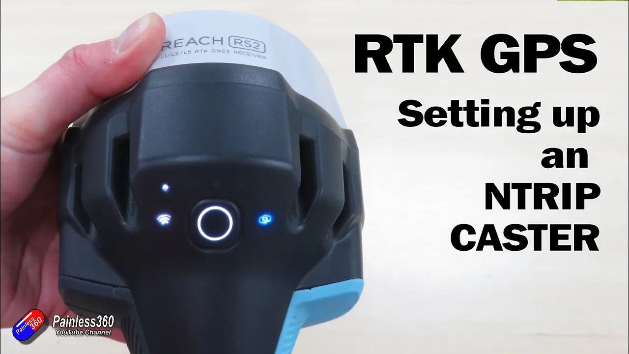
RTK GPS: Setting up an NTRIP Caster (with Ben from 3DXR)
4.8K
RTK (Real-Time Kinematic) GPS technology enhances standard GPS accuracy from meters to subcentimeter precision by using a fixed base station that monitors GPS signal variances and transmits corrections to mobile receivers. NTRIP (Networked Transport of RTCM via Internet Protocol) casters enable distribution of these corrections over internet connections, extending operational range beyond line-of-sight radio limitations to approximately 20 kilometers. This technology serves professionals including surveyors, architects, archaeologists, and drone operators who require precise spatial measurements. Emlid's Reach series offers accessible NTRIP caster solutions with free tiers supporting multiple mount points and simultaneous connections.
Click to watch →

Live - NORDIAN NTRIP O que é o NTRIP Nordian
753
NTRIP (Networked Transport of RTCM via Internet Protocol) enables centimeter-level GNSS precision without physical base stations. Unlike single-base systems limited to 10-20km, NTRIP networks provide multiple reference stations across coverage areas, transmitting all GNSS constellations (GPS, GLONASS, Galileo, Beidou) and all frequency bands (L1, L2, L5, L6). Reference stations calculate atmospheric and satellite errors, transmitting data to central servers that calculate position-specific corrections. Applications include drone mapping (DJI Enterprise series), precision agriculture, topography, and autonomous vehicles. The system uses RTCM protocol with PPP RTK technology achieving 3cm horizontal precision. Not all equipment supports NTRIP—only professional equipment with RTK-capable receivers can utilize it. Subscription plans range from 10-hour test (~$13.95) to annual (~$499.95), providing cost-effective access compared to physical base stations ($25,000-$30,000).
Click to watch →

Contratiempos y aciertos de la implementación del caster experimental basado en NTRIP en Ecuador
475
This segment explains the NTRIP (Network Transport of RTCM via Internet Protocol) for real-time GNSS corrections. Unlike traditional radio-based differential corrections, NTRIP uses internet packets to transmit correction data, eliminating distance limitations. The segment describes the caster system architecture consisting of reference stations, a central server, and user receivers. The presenter explains how correction data flows from reference stations to the caster server via internet connections, then to users. The segment covers implementation requirements including continuous internet connectivity and discusses the evolution from 2G to 4G networks improving real-time performance.
Click to watch →
Deep Dive
Basic cellular communication concepts, including SIM card activation, APN (Access Point Name) configurations, and TCP/IP networking.

Blackvue DR750-2CH LTE Cloud Dash Cam
74.1K
After connecting to the dash cam's Wi-Fi, activate the SIM card by: (1) Tapping the SIM card button in the app, (2) Entering the cell phone provider's APN (Access Point Name) settings, (3) For T-Mobile in the US, select the T-Mobile APN option, (4) Skip username and password fields, (5) Save to activate. This enables the dash cam to connect to the internet via the SIM card.
Click to watch →

Unboxing y Review Pillo Fon | OMV de Luisito Comunica
14.9K
This segment details the complete SIM card activation process and mobile data configuration. The presenter walks through inserting the SIM, receiving activation messages, and completing the activation via the Diri app. A critical technical step involves configuring the APN (Access Point Name) settings, where the presenter demonstrates adding a new APN with the specific settings for Diri Telecomunicaciones (internet.ddiri.com). Without proper APN configuration, mobile data connectivity will not function even after successful SIM activation.
Click to watch →

como Registrar o Activar SIM CARD WOM (muy fácil)2024
166.7K
This tutorial demonstrates how to activate and register a WOM SIM card, configure APN settings for data connectivity, and perform number portability to switch carriers while keeping the same phone number. The process involves using the carrier's website to complete registration with personal identification details, configuring APN settings through the device's network settings menu (typically accessed via Settings > SIM & Mobile Networks > Access Point Names), and entering the correct APN credentials (such as 'internet.uom') to establish data connectivity.
Click to watch →

G16 + SP reporte a CRA, Transmisión de eventos o señales de alarma Paradox con TRIKDIS a Monitoreo
2.8K
This segment details the critical configuration steps for connecting the module to a monitoring center. Essential topics include: obtaining and entering the monitoring center's IP address and port (default: 8766); configuring TCP/IP communication protocol; setting up SIM card APN settings (e.g., internet.claro.com.co for Colombian Claro); and understanding the importance of accurate configuration for reliable alarm reporting. The module requires proper SIM card installation with correct APN settings to enable cellular data communication for alarm transmission.
Click to watch →

ガラケー廃止!スマホ移行前に知っておきたい話
780K
After SIM installation, configure APN (Access Point Name) settings for internet connectivity. Navigate to Settings > Wireless and Network > Access Point Names. Use existing carrier settings or create new ones by tapping 'New APN.' Configure five fields: Name, APN, Username, Password, and Authentication Type. All characters must be in half-width format. Save settings to apply changes. Most connectivity issues stem from typing errors in these settings.
Click to watch →
Prerequisite Knowledge
- Concept 01Fundamental principles of GNSS (Global Navigation Satellite Systems), including satellite signal propagation, atmospheric delays, and standard GPS positioning limitations.
- Concept 02The theoretical basis of RTK (Real-Time Kinematic) positioning, specifically how carrier-phase measurements and differential corrections differ from code-phase pseudo-ranges.
- Concept 03The concept of NTRIP (Networked Transport of RTCM via Internet Protocol), including the roles of Casters, Servers, Clients, and Mountpoints.
- Concept 04Basic cellular communication concepts, including SIM card activation, APN (Access Point Name) configurations, and TCP/IP networking.
Subsequent Learning
- Step 01Integration of high-precision RTK coordinate data into robotic autopilot systems (such as ArduPilot, PX4, or ROS 2) for autonomous navigation.
- Step 02Understanding coordinate reference systems (CRS), geodetic datums (e.g., WGS84 vs. NAD83), and local height transformations (ellipsoidal vs. orthometric).
- Step 03Implementing PPK (Post-Processed Kinematic) workflows as an alternative high-precision methodology when real-time 4G cellular connection is lost.
- Step 04Setting up and hosting a private physical RTK Base Station and NTRIP Caster to broadcast custom correction streams to rover networks.
Kit Overview
Setup Steps
Kit Overview
0:02Playing Section
- 1
The starter kit enables RTK positioning via cellular networks.
- 2
It integrates internet, GNSS engine, and correction services.
- 3
Includes various connectors for external devices and antennas.
Limitations of Cellular-Based NTRIP: The Case for Local UHF Radio and Satellite PPP
While 4G NTRIP offers convenient centimeter-level accuracy, its absolute reliance on cellular network infrastructure presents significant limitations. In remote agricultural fields, dense forests, or deep valleys where precision GPS is frequently required, cellular coverage is often weak or nonexistent, rendering 4G-dependent RTK useless. Additionally, NTRIP introduces recurring cellular data fees, potential latency, and dependency on third-party caster uptime. Two primary alternative architectures address these challenges: 1. Local UHF/VHF Radio RTK: By using a local physical base station transmitting corrections directly to the rover via radio, developers achieve zero-latency, subscription-free, centimeter-level accuracy that operates entirely independent of the internet. 2. Satellite-Delivered PPP (Precise Point Positioning): Technologies such as L-band correction services (e.g., PointPerfect or Trimble RTX) broadcast correction data directly from geostationary satellites. This eliminates the need for both local base stations and cellular networks, offering high-precision global positioning even in the most isolated environments.
Deep Dive
Integration of high-precision RTK coordinate data into robotic autopilot systems (such as ArduPilot, PX4, or ROS 2) for autonomous navigation.

GRTK INTRODUCTION:High-precision positioning orientation module for autopilot | Ardupilot
1.5K
The Blicube GRTK is a high-precision positioning module based on NMEA statements that enables centimeter-level RTK positioning when used with two modules (one as base station and one as rover), featuring dual-antenna orientation capability that eliminates the need for magnetic compass calibration and interference issues, supporting autonomous driving applications for drones, vehicles, and boats with plug-and-play functionality and wide voltage input (5-35V).
Click to watch →

Ryan Friedman ROS2
1.5K
This video presents the architecture and design goals for integrating ArduPilot flight controller with ROS 2, focusing on lowering the barrier to entry for autonomy developers by providing standardized tooling, consistent coordinate systems (WGS84), and common message formats, while addressing challenges like terrain-aware navigation and smart RTL (Return to Launch) planning that avoids obstacles.
Click to watch →

PX4 & ROS2 Integration: Drone Teleoperation in Gazebo (Joystick Control) #drone #ros2 #px4
2.5K
This workshop demonstrates how to integrate PX4 autopilot with ROS2 using micro XRCE DDS middleware, covering the complete workflow from setting up PX4 SITL simulation in Gazebo, configuring QGroundControl for ground station operations, implementing offboard control with three essential pillars (QoS compatibility, heartbeat at 2+ Hz, and continuous setpoints), and finally achieving joystick-based teleoperation through coordinate frame transformations between NED and FLU systems.
Click to watch →

How to start making AUTONOMOUS ROBOT with the ATTLER
94.1K
PID tuning is the most time-consuming process for robot operation. Throttle tuning requires cruise learning in manual mode to establish baseline speed data, followed by PID parameter adjustment using the tuning graph in acro mode. Steering tuning begins with feedforward (FF) value baseline, then adjusts P and I parameters. RTK GPS implementation involves setting up a base station with F9P GPS module outputting correction data via UART, transmitted to a rover unit that injects corrections into Mission Planner. RTK Float provides 10-20cm accuracy, while RTK Fixed achieves approximately 1cm accuracy when antenna is 1-2 meters above ground.
Click to watch →

UAV Design and Applications: Autonomous Relative Navigation and GNSS Robustness for UAV Systems
908
Professional UAV platforms require modular RTK integration compatible with existing autopilot systems (ArduPilot/Pixhawk). Key considerations include dual-frequency receivers for improved performance, hot-shoe camera synchronization (critical for accuracy - side-input triggers cause 5-50ms delays translating to 70cm errors at 14m/s), and systematic RFI mitigation through shielding and component separation. The largest interference source may unexpectedly come from the camera payload. Data flows through autopilot firmware and ground control station software, with corrections delivered via telemetry links or RTK networks.
Click to watch →
Deep Dive
Understanding coordinate reference systems (CRS), geodetic datums (e.g., WGS84 vs. NAD83), and local height transformations (ellipsoidal vs. orthometric).

Coordinate System Jargon: geoid, datum, projection
128.1K
Datums are reference systems that define how an ellipsoid fits to the geoid. Since no single ellipsoid perfectly matches Earth's irregular shape, different datums make trade-offs in accuracy across different regions. WGS84 (World Geodetic System 1984) attempts to fit the entire world as accurately as possible, while NAD83 (North American Datum 1983) focuses specifically on North America for greater regional accuracy.
Click to watch →

FE Debate vs Fung
15.8K
Surveyors distinguish between orthometric height (elevation above mean sea level) and ellipsoid height (distance from Earth's ellipsoid surface). Orthometric height is what people commonly think of as elevation, while ellipsoid height is used in GPS calculations. The difference between these heights is due to Earth's oblate spheroid shape. Surveyors use the Cartesian coordinate system (x, y, z) to represent positions on Earth's surface, combined with Earth's known shape parameters.
Click to watch →

測量士補過去問解説令和2年度まとめ
12.5K
This section covers geodetic concepts: (1) The Surveying Law specifies GRS80 (Geodetic Reference System 1980) as the standard ellipsoid, while WGS84 is used by GPS; (2) The geoid is the equipotential surface approximating mean sea level with irregularities from mass distribution variations; (3) Orthometric height (標高) is measured from the geoid, while ellipsoidal height is measured from the ellipsoid; (4) The difference between these heights is the geoid undulation (ジオイド高); (5) Orthometric height = ellipsoidal height - geoid undulation.
Click to watch →

TERMOS E VOCABULÁRIOS DO GNSS RTK - Topoflow #005
556
Coordinates are numerical values defining specific locations on Earth, expressed in different systems: Cartesian (X, Y, Z) for station totals, or geographic (latitude, longitude, altitude) for GNSS. A datum is a mathematical model defining Earth's orientation relative to the coordinate system. In Brazil, CGCS2000 with WGS84 ellipsoid is the standard. Height ellipsoidal is measured from the mathematical ellipsoid model, while height orthometric is measured from the actual Earth's surface to the geoid (mean sea level). The IBGE provides tools to convert between these height systems.
Click to watch →
Class 22 - A Practical Introduction to GIS
209
GIS requires accurate Earth surface representation. Earth is modeled as an ellipsoid (flattened at poles, semi-major axis 6378.137 km) rather than a sphere. The geoid represents Earth's true shape based on gravity measurements. Datums determine ellipsoid parameters: global datums center on Earth's mass (WGS84), while local datums optimize for specific regions. Geographic CRS uses latitude/longitude on ellipsoids (WGS84, EPSG 4326) for location but cannot measure distances accurately. Projected CRS uses flat surfaces with X, Y, Z coordinates and linear units for GIS computations.
Click to watch →
Deep Dive
Implementing PPK (Post-Processed Kinematic) workflows as an alternative high-precision methodology when real-time 4G cellular connection is lost.

Modo PPK con GNSS Hi-Target
1.2K
This video provides a comprehensive tutorial on PPK (Post-Processed Kinematic) technology using GNSS High Target equipment. The workflow covers: (1) Understanding PPK principles where differential correction occurs during post-processing rather than real-time; (2) Field configuration where the base station operates in static mode recording GNSS observations, and the mobile receiver activates GNSS closed data recording; (3) Post-processing in HBC software including data transfer, project creation, coordinate calculation using stop-go mode, and result export in DXF, CSB, or PDF formats. This method ensures accurate surveying even when real-time signal correction is lost.
Click to watch →

PPK Post-Processing Kinematic - Emlid Studio Tutorial
74K
PPK (Post-Processing Kinematic) is a GNSS technique that allows surveyors to achieve high-accuracy positioning by collecting raw satellite observations independently on both base and rover receivers without real-time communication, then applying corrections during post-processing using specialized software like Emlid Studio; this method provides full control over coordinate adjustments compared to RTK's automated real-time corrections, making it essential when real-time connectivity is unavailable due to distance, lack of correction networks, or other constraints.
Click to watch →

How To Map with Reach and DJI RTK drone | Expert Tips on RTK and PPK Workflows
25K
This video explains how to achieve high-accuracy drone mapping using two correction methods: RTK (Real-Time Kinematic) provides immediate centimeter-level accuracy during flight by receiving real-time GNSS corrections from a base station via NTRIP caster, while PPK (Post-Processed Kinematic) records raw GNSS data during flight and applies corrections later using post-processing software, making PPK more suitable for areas without mobile data coverage; both workflows achieve sub-centimeter accuracy when combined with proper flight planning (cross-hatch patterns, adequate overlap), and the choice between them depends on site conditions, equipment availability, and project requirements.
Click to watch →

GCPs vs PPK vs RTK Drone Mapping Webinar and Identified Technologies CEO Dick Zhang Q&A
39.8K
PPK (Post-Processed Kinematic) is generally preferred over RTK (Real-Time Kinematic) and GCPs (Ground Control Points) for drone mapping because it offers similar accuracy (approximately 1/100th of a foot average error) while providing greater flexibility, reliability, and cost-effectiveness; unlike RTK which requires continuous real-time connection and can lose all data if connection drops, PPK can reference previous and future data, making it more dependable for autonomous drone flights.
Click to watch →
RTK, NTRIP & PPK Explained: How GNSS Achieves Centimeter-Level Accuracy
15.3K
RTK (Real-Time Kinematic) achieves centimeter-level GNSS accuracy by using a second nearby receiver to eliminate atmospheric errors that affect GPS signals; the system employs pseudo-range measurements and carrier phase tracking with ambiguity resolution algorithms, with single-band receivers supporting baselines up to 10km and multi-band receivers extending to 60km. When real-time corrections aren't available, NTRIP networks deliver corrections over 3G/4G networks with no range restrictions, while PPK (Post-Processing Kinematic) allows post-survey data combination for precise positioning.
Click to watch →
Deep Dive
Setting up and hosting a private physical RTK Base Station and NTRIP Caster to broadcast custom correction streams to rover networks.
RTK GPS: Setting up an NTRIP Caster (with Ben from 3DXR)
4.8K
An NTRIP caster is a system that broadcasts RTK GPS corrections over the internet, allowing multiple rovers (drones, survey equipment) to receive subcentimeter accuracy corrections from a single base station within a range of up to 60 km; the setup involves registering for a free account, configuring the caster with the base station's credentials (IP address, port, mount point, password), and then entering those same credentials into the rover device (such as through Mission Planner) to establish a connection and enable RTK positioning.
Click to watch →

Setting up a low-cost DIY RTK Base Station based on the UM980 module
18.5K
This video demonstrates how to configure a Unicore UM980 GNSS module as a low-cost RTK base station by first establishing communication through the manufacturer's software, monitoring satellite constellations using GNGSV commands, configuring the module for base station mode with appropriate signal groups, and streaming RTCM correction data (including RTCM 1077 for GPS, 1087 for GLONASS, 1097 for Galileo, 1117 for QZSS, and 1230 for BeiDou) to an NTRIP caster like RTK2Go for centimeter-level positioning accuracy.
Click to watch →

5 Minute Modules - NTRIP, RTK and Base Stations
115K
A base station is a stationary GPS receiver that collects position data to correct errors in moving GPS receivers (rovers) through differential GPS techniques; RTK (Real-Time Kinematics) uses carrier phase measurements to achieve centimeter-level accuracy, with 'fixed' RTK resolving integer ambiguities exactly and 'float' RTK providing approximate solutions; NTRIP (Network Transport of RTCM via Internet Protocol) enables transmitting these corrections over the internet using a server (base station), caster (data aggregator), and client (receiver software) architecture.
Click to watch →
Emlid NTRIP: Configuración Rápida
250
This segment covers the complete process of setting up NTRIP communication between a base station and rover. It begins with logging into the Emlid account and understanding the two types of credentials: base station credentials for configuring the base, and rover credentials for configuring the rover or applications like Flow. The same credentials also apply to drone RTK operations. The process then moves to configuring the base station by selecting NTRIP as the output method, entering server address, port, username, password, and mount point. Connectivity requirements are emphasized, including Wi-Fi connection or mobile data activation. Finally, the base station coordinate configuration is demonstrated, including coordinate input, antenna height, and averaging time settings (typically 10 seconds).
Click to watch →
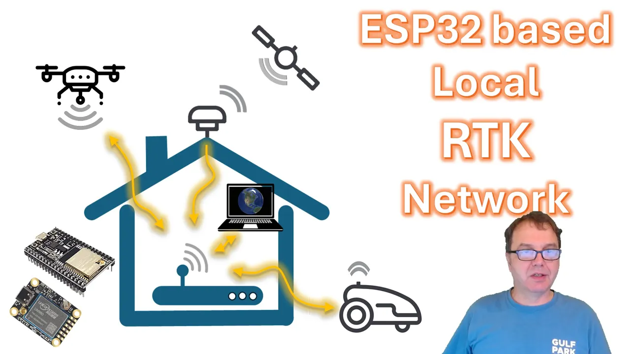
ESP32 based Local RTK Network
8.1K
This video tutorial demonstrates how to configure an ESP32-based NTRIP master to transmit RTCM correction data and GPS position data over a local Wi-Fi network between a base station and rover, eliminating the need for internet-based NTRIP servers. The setup involves configuring the ESP32 as a socket server (port 23) to receive commands from a laptop, setting the base station in fixed mode with precise coordinates, and configuring the rover to connect to the local NTRIP caster. This enables remote configuration of base stations located in inaccessible areas like garages, and allows real-time position monitoring and correction delivery within the local network.
Click to watch →
Kit Overview
Setup Steps
Kit Overview
0:02- 1
The starter kit enables RTK positioning via cellular networks.
- 2
It integrates internet, GNSS engine, and correction services.
- 3
Includes various connectors for external devices and antennas.
Limitations of Cellular-Based NTRIP: The Case for Local UHF Radio and Satellite PPP
While 4G NTRIP offers convenient centimeter-level accuracy, its absolute reliance on cellular network infrastructure presents significant limitations. In remote agricultural fields, dense forests, or deep valleys where precision GPS is frequently required, cellular coverage is often weak or nonexistent, rendering 4G-dependent RTK useless. Additionally, NTRIP introduces recurring cellular data fees, potential latency, and dependency on third-party caster uptime. Two primary alternative architectures address these challenges: 1. Local UHF/VHF Radio RTK: By using a local physical base station transmitting corrections directly to the rover via radio, developers achieve zero-latency, subscription-free, centimeter-level accuracy that operates entirely independent of the internet. 2. Satellite-Delivered PPP (Precise Point Positioning): Technologies such as L-band correction services (e.g., PointPerfect or Trimble RTX) broadcast correction data directly from geostationary satellites. This eliminates the need for both local base stations and cellular networks, offering high-precision global positioning even in the most isolated environments.
Fundamental principles of GNSS (Global Navigation Satellite Systems), including satellite signal propagation, atmospheric delays, and standard GPS positioning limitations.
The theoretical basis of RTK (Real-Time Kinematic) positioning, specifically how carrier-phase measurements and differential corrections differ from code-phase pseudo-ranges.
The concept of NTRIP (Networked Transport of RTCM via Internet Protocol), including the roles of Casters, Servers, Clients, and Mountpoints.
Basic cellular communication concepts, including SIM card activation, APN (Access Point Name) configurations, and TCP/IP networking.
Integration of high-precision RTK coordinate data into robotic autopilot systems (such as ArduPilot, PX4, or ROS 2) for autonomous navigation.
Understanding coordinate reference systems (CRS), geodetic datums (e.g., WGS84 vs. NAD83), and local height transformations (ellipsoidal vs. orthometric).
Implementing PPK (Post-Processed Kinematic) workflows as an alternative high-precision methodology when real-time 4G cellular connection is lost.
Setting up and hosting a private physical RTK Base Station and NTRIP Caster to broadcast custom correction streams to rover networks.
3.8K views33likes2:43@ardusimpleOriginal Release: 2024-03-01
Ru simple 4G and trip starter kit is the easiest way to enjoy rtk in any location with cell phone coverage thanks to the integrated internet access if you're utilizing an rtk correction service just add your sim card and enjoy centimet level accuracy location data the board is powered by f9p rtk engine and receives L1 L2 and e5b bands from GPS glonass Galileo and B the for gen trip Master gives you the possibility of reception and transmission of Serial Port data to and from internet it utilizes the same 2G 3G or 4G cellular technology as your mobile phone does the kit allows you to connect to an ntp server to download correction data while simultaneously transmitting its position to another server actually this product has many more built-in features such as NT client ntip server TCP UDP socket client and point perfect client no need for programming at all the board has a jst connector for linking to your favorite pixhawk autopilot and Arduino rails in case you use it together with an Arduino Raspberry Pi or any other development board to connect to your PC tablet or mobile phone there is an onboard USBC connector Additionally the board is equipped with an XP plug-in socket to connect your 4G accessory in the future if you want to change the functionality of your board you can simply replace the 4G plugin by any other connectivity plugin the antenna has two mounting holes for fixed installation and a magnetic base making it easy to place on a metal surface it comes with 5 m length cable ending in an SMA mail connector to use your kit first attach two antennas to the modem's UFL connectors and position them as far away as possible from each other to maximize the signal reception configure the modem from the secondary USBC connector following the instructions in the user guide all without any need for programming simply use a configuration tool note that the USB cable is not included in the kit but from our experience everybody has USB cables at home finally simply introduce the SIM card connect the gnss antenna in the location with good view of the sky and power the board and let the simple rtk2 be for starter kit do the rest you will find the configuration tool and more useful information on rdus simple.com plus we deliver worldwide in two to four business days
Up Next

9:29
Kalman Filter Tutorial: MATLAB Implementation with Bayesian NINJAS
@TheScienceguy3000
380K views•2011-04-26

30:32
Ultrasonic Transducers: Resonant Frequency Measurement and Horn Design
@imajeenyus42
229.9K views•2017-02-22

54:16
Polymer Environmental Degradation: Mechanisms & Stabilization
@iit
1.8K views•2012-07-10

33:39
How a Student's Question Saved a NYC Skyscraper from Collapse
@veritasium
22.8M views•2025-04-26
Related Study Plans & Knowledge Roadmaps
Structured learning paths in Engineering
engineering
Building Acoustic Levitators: Physics & Arduino
01The Physics of Sound and Standing Waves
02Piezoelectric Transducers and H-Bridge Drivers
03Arduino Programming: Generating 40 kHz Signals
+ 2 more learning modules
14h5 modules
Explore Roadmap
engineering
Building Peltier Cloud Chambers: Particle Tracks
01Cosmic Rays & Cloud Chamber Physics
02Thermoelectric Cooling (TEC) Fundamentals
03Custom Liquid-Cooling Loop Design
+ 2 more learning modules
18h5 modules
Explore Roadmap
engineering
Yagi-Uda Antennas: Modeling, Build & VNA Test
01Introduction to RF and Antenna Fundamentals
02Yagi-Uda Antenna Design Principles
03Antenna Modeling and Simulation in 4NEC2
+ 2 more learning modules
18h5 modules
Explore Roadmap
engineering
ECG Monitor Design: Op-Amps, Filters & Noise
01Electronics & Breadboard Basics
02Op-Amps and Instrumentation Amplifiers
03Bioelectricity and ECG Fundamentals
+ 2 more learning modules
18h5 modules
Explore Roadmap