





























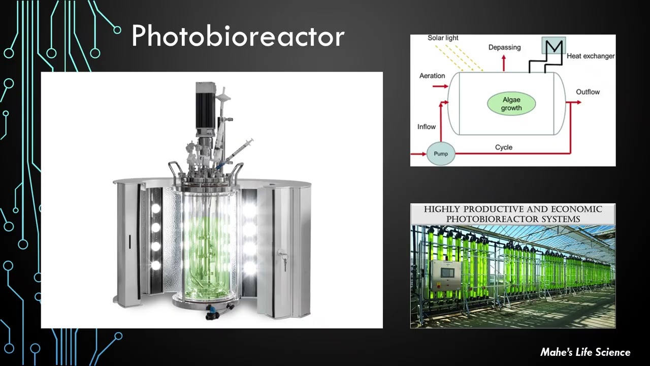
This video demonstrates the design and construction of an automated photobioreactor system for cultivating spirulina algae, highlighting the trade-offs between reactor geometry (light path length affecting productivity exponentially), airlift circulation for mixing without mechanical damage, LED lighting optimization for growth, and turbidostat control systems for maintaining target algae density. The project illustrates how home-built, modular designs using 3D-printed components and microcontroller automation can achieve controlled algae cultivation for potential applications in sustainable feed production and pharmaceutical compound synthesis.
Photobioreactor Design and Algae Cultivation: A DIY Turbidostat Build
Added:Fundamentals of photosynthesis and microalgal biology, specifically the growth requirements of cyanobacteria like Spirulina (Arthrospira platensis) including light, carbon dioxide, pH, and macronutrient balance.
Basic bioprocess engineering concepts, particularly the operational differences between batch, fed-batch, and continuous cultivation modes (such as chemostats and turbidostats).
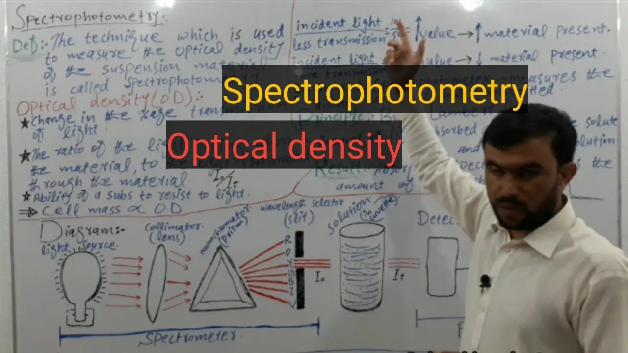
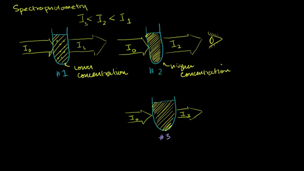
The principles of spectrophotometry and turbidimetry, specifically how optical density (OD) and the Beer-Lambert Law are used to estimate biomass concentration in a liquid medium.
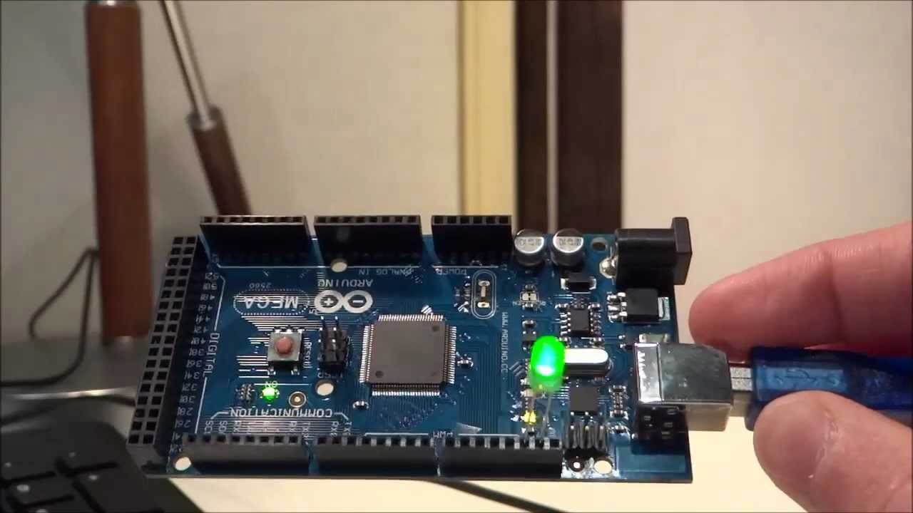
Elementary electronics and microcontroller programming (e.g., Arduino or Raspberry Pi platforms) for interfacing with sensors (pH, temperature, photodiodes) and actuators (pumps, LEDs).
Industrial scale-up methodologies for photobioreactors, including addressing challenges like light limitation, shear stress, mass transfer rates of CO2, and thermal regulation in large volumes.
Downstream processing techniques for microalgae, such as flocculation, centrifugation, filtration, and drying for the extraction of high-value proteins, lipids, or pigments.
Advanced closed-loop control system designs, including PID controller tuning and machine learning algorithms to dynamically optimize growth rates and nutrient dosing.
Comparative analysis of alternative photobioreactor geometries (e.g., tubular, flat-panel, bubble-column designs) to evaluate their economic and biological feasibility.
47K views2.6Klikes21:22Original Release: 2023-11-09
In this video, I'll be showcasing the design and construction of an automated photo-bioreactor system to grow an algae called spirulina. Different types of cultivation systems have been researched by academia to grow various strains of algae with the overarching goal of harnessing the efficiency of these organisms in a scalable economic manner.
The reactor I am showcasing will serve as a testbed to further explore a combination of ideas to achieve this goal. The reason I'm publishing my work is to connect with others who are researching similar topics and to obtain feedback.
The first question to address is why would anyone want to grow Algae.
The application that initially drew me to start my research is the use of algae as feed for livestock and aquacultures. While different algae have tremendous nutritional value for people who consume them around the world, I find it far more compelling to feed the algae to animals that we then consume. In theory, algae is a far more efficient biomass when compared to traditional animal feed like wheat or corn. Crops have to spend lots of energy to fight gravity while algae on the other hand is suspended in water. Currently, the cost of cultivating and harvesting the algae is still too high for it to be a competitive biomass. I will go into some of the variables that contribute to this cost as I explain the currently employed solutions.
Various industrial products can also be extracted from algae. One idea that was trending in the startup world in the last decade was to produce biofuels like biodiesel from algae. Most of these companies have since learned through bankruptcy that it is very difficult to compete with traditional fuels that are relatively inexpensive to just dig up from the ground. The companies that survived seem to have all pivoted into the other products that can be produced using algae.
I believe that pharmaceutical products grown by algae are the easiest to scale as they can afford to grow the cells at a higher cost when compared to biomass used for feed or industrial applications. There are already some industrial-scale successes that use algae to grow different compounds like fatty acids. The environmental offering is more of a win-win situation where the algae can use waste gases and minerals in wastewater to grow.
In my project, I am not focusing on the downstream products that the output of my system can be used for. Of course, algae grow in nature almost uncontrollably. When it comes to farming a specific strain it is a multistage process. The first step is cultivating the algae by providing it with the correct conditions to grow. Here I am talking about phototrophic growth where the algae photosynthesizes to grow. For phototrophic growth, algae require visible light, water, and carbon dioxide. In addition, providing the strain you are growing with the correct nutrients and providing an environment that has the ideal temperature and PH unlocks its full growth potential. After cultivation, the cells are ultimately washed and dried if they are being used as a biomass or additional chemical steps can be completed to produce specific products. In this project, I am only focusing on the cultivation phase of the process. I have chosen to grow the algae spirulina specifically, for 2 main reasons. 1st it is easy to buy a live culture from other growers and 2nd it likes to grow at a high PH which reduces the sterility requirement that other strains may need. The high PH prevents other organisms from growing in the otherwise favorable environment.
There are two general categories of cultivation systems used in industry. Open and closed systems.
What is meant by open systems is that they are exposed to the elements. These images are of the commonly used raceway pond designs. They have a divider in the middle and a paddle wheel that creates flow and induces mixing. Open ponds are inexpensive to construct when compared to closed systems but they have inherent disadvantages. The first disadvantage is algae shading. As the algae culture grows denser, the light reaching the cells decreases with depth. This results in low-density cultures or ponds being constructed with very short depth which reduces their volume.
The other disadvantages all have to do with the lack of control that comes with these open systems. Contamination can cause huge losses and additional expenses as the cultivators are continuously fighting to keep the algae they are growing as the dominant strain. This is achieved through continuous testing and the use of pesticide control. Closed reactors alleviate these disadvantages. The geometry of the system is the main factor that can control the light path to reduce the problem of algae shading. The closed system being further removed from the elements makes it easier to manage. There are various designs of these closed systems. They are called photobioreactors. The disadvantages of these systems are their high capital cost to build and costlier maintenance requirements to prevent cells from sticking to the reactor walls and blocking the light. This chart explains the important tradeoff of the culture's light path which is dictated by the reactor's geometry. As the light path, which can be thought of as the thickness of the reactor, increases the productivity measured in volume output rate decreases exponentially. On the other hand, when the light path is decreased, the exponential increase in productivity is deterred by the linear decrease of the ratio of culture volume to irradiated surface area.
This decrease would correlate with an increase in the price of the bioreactor as more surface area or building material would be required to hold a larger volume. The cost correlation would depend on the shape and the material the reactor is constructed from. This tradeoff is at the heart of the design of most bioreactors. For my initial guess, I am keeping my reactor's light path on the shorter side between 2 and 6 cm. Now let's get into my photobioreactor design.
My reactor is constructed out of 2.5-diameter clear pipes that are meant for shop vac systems.
It uses 2 straight sections and 4 90-degree bends to create a continuous loop. The loop is connected by 6 couplers, 3 at the bottom and 3 at the top. Here is a cross-section view that makes it easier to visualize how the parts come together. The couplers have unique features that serve different purposes. Each of the couplers is made of 3 3D printed parts. They are made of 2 caps shown in blue that sandwich 2 O-rings shown in black on both sides of a printed hub shown in red. The caps are sandwiched using 8 bolts that go around them. The pressure on the O-rings alone creates enough force to keep the pipes in place as well as prevent any water from leaking from the system. The 2 horizontal couplers on the bottom are the airlift couplers. They have internal geometry that can distribute air from an air pump into little bubbles. The red hub has an opening to the outside where a pneumatic fitting connects the airline. This then goes to a chamber that revolves inside the walls of the part and distributes the air to 16 1.5 mm holes around the inner diameter of the part. The bubbles that come out of these holes then rise to the top of the vertical pipe, pulling the water around them and thus creating flow. The internal geometry of such a part can only be made using 3D printing. It was designed not to have any overhangs to prevent the need for support material. This mechanism is called an airlift pump. It is advantageous to use this style of pump that does not have any moving parts touching the algae as a mechanical pump with an impeller would break down and kill the algae cells. The air is supplied to the airlift couplers from an aquarium air pump. Each line has a valve to throttle the airflow and a check valve to prevent water from entering the pump when it is off. While one valve is kept fully open the other is throttled to produce less air. This creates flow in the direction indicated by the arrows.
I'll explain later why it is important to have airlift on both sides. The next subsystem is the lighting system. While I could rely on sunlight to get all the light the algae needs for growth.
I opted for an LED strip wrapped around one of the tubes since I can get a consistent amount and duration of light to standardize testing. The LED strip is powered by a benchtop power supply that can change the amount of light using the supplied voltage. the power supply is then connected to a smart plug that can be programmed to follow a scheduled cycle. The reason I chose red LEDs is because other research has shown that spirulina grows fastest when using the red wavelengths as seen in the graph on the left. The graph on the right shows an important relationship between the circulation and light subsystems. When light intensity is initially increased, the growth rate increases but further increasing light intensity comes with diminishing returns followed by a negative impact on growth. This phenomenon is called photo-inhibition and can be thought of as the overstressing of cells by getting too much light in a short duration.
As the graph shows, the light intensity can be further increased as long as circulation speed is also increased to prevent the extensive exposure of cells to high-intensity light.
The final subsystem is the dilution and extraction control system. This is what makes the bioreactor automated. For those from the industry, this is a turbidostat setup. The idea of a turbidostat is to have the reactor maintain a chosen algae density by continuously monitoring the density and diluting the culture with new media to counteract the algae's growth. As you can see in this chart, productivity initially increases with culture density but then starts dropping when shading comes into effect. One way to make use of more efficient densities is by increasing the light intensity reaching the reactor. The aim of the control system is to hold whatever density I specify while I change other reactor variables with the goal of increasing the dilution frequency which would correlate to growth productivity. At the heart of the dilution system is a peristaltic pump I made out of a stepper motor, 3D-printed parts, screws, and bearings. The pump has two separate levels that are attached to the motor shaft, essentially moving a similar amount of liquid with each rotation in 2 separate lines. The brain of this system is an esp32 microcontroller.
I programmed the controller to complete various tasks. The controller tells the pump when and how long to turn on. It also records data from a sensor and pushes it to an online database so that I can monitor it remotely. As an added bonus the values on the controller that dictate the dilution and sampling process can be changed using an app on my phone. This will be especially useful during the tuning phase. The turbidity sensor is how I measure the culture's density. Turbidity sensors work by passing light generated from an LED through the sample and the remaining light is detected by a photoresistor on the other side. They basically measure the sample's absorbidity and as the culture density increases the measured light absorbance increases. My initial plan is to have one line pump water from the nutrient media reservoir into the reactor and then a second line draw an equal amount of algae water from the reactor, through the turbidity sensor, and then into the extracted algae container. I quickly found out that this idea wouldn't work because any imbalance in the volume pumped between the 2 lines would cause the reactor to overflow or dry up over time. Instead, I rerouted the second line back into the reactor so that the sample taken for density measurement was returned to the reactor. In each sampling cycle, the pump first flows backward and then forwards to prevent the dilution line from adding any water into the reactor. To extract the displaced algae water from the reactor during dilution I created an overflow feature into the top coupler which can drain using gravity into the extracted algae container. The fill port at the top of the coupler is where the reactor is filled, where the lines are fed through, and how air can escape the system. You can see in the cross-section, that the coupler has a stem that goes to the center of the pipe. When the system dilutes the water level rises and drains through the stem and the brass adapter which connects to a tube.This sums up the design of the reactor. For the record, this design is not novel. There are others who have made and tested similar designs. The achievement here was making this kind of design at home using off-the-shelf components.As I mentioned at the start of the video one important aspect of such a system is that it can be scalable. While I am only building one unit for testing. This is how many units could be combined together to build a large network that would be connected together from the top. That is it for the design phase now to build. 16?I printed all 6 couplers using a strong plastic called PETG.
After printing, critical surfaces were sanded and parts were coated in clear acrylic to make them watertight. Here is a demo of how one of these couplers is installed. I start by pressing the caps on the 2 parts I am connecting. Next, I seat a square O-ring into a groove formed by the pipe walls and the cap making sure it's not twisted. I then fit the hub in the middle between the parts making sure it's oriented correctly and then align the caps. Throughout the process, I press down on the parts onto the desk to make sure they are aligned perfectly. Any misalignment causes issues down the line. 8 screws and nuts go around the coupler to tighten the caps and squeeze the rings.
I go around tightening screws on opposing sides to ensure an equal amount of pressure on the O-ring.
I then got the other sides of the pipe ready for their next connection. I did the same with the bottom side of the reactor. I then put it all together by connecting the top and bottom bends with the 2 vertical pipes. Making all the coupler connections in a similar way. I took the reactor outside for a leak test. Placed a funnel through the fill port and I tied a knot in the overflow line to prevent it from draining any water while I was filling. This is the aquarium air pump with the valves I mentioned earlier. I connect the airlines to these pneumatic fittings that are used on 3D printers. The check valves have to be in place before filling to prevent the water from escaping through the airlift couplers. I intentionally filled the reactor above the overflow line to test this feature. There was a leak coming from one of the airlift couplers so I had to drain the system to troubleshoot it. I ended up recoating the hub section of the coupler, swapping out the pneumatic fitting, and ensuring the rings were seated correctly. I refilled the system and that seemed to fix it. While there are bubbles coming out of both sides you can see at the top that flow is moving from left to right because of the difference in airflow. If you look closely at the right side you can tell the water is flowing downwards by the movements of small particles in the water. The picture on the left depicts why I need airlift couplers on both sides. the first time I ran this system I only had an airlift on one side. So by having reduced air flow coming out of the second side, it should prevent the build-up of algae on the downward flowing side. It also allows me to swap flow direction between clockwise and counterclockwise.
I started off with a small volume of spirulina culture. I grew it in glass jars placed near a window to have enough volume for the bioreactor. The culture media is made by mixing 3 components into filtered water. Sodium bicarbonate raises the pH to the target of 10 and also provides carbon for the spirulina to grow. Maxigro is a premixed nutrient mix made for hydroponics.?the first step to bringing the reactor into operation was mixing up 8 L of media, I then filled the reactor with this media. Next, I poured about half a liter of dense algae into the reactor. this power cord provides power to the whole system. It first goes to a smart plug that supplies this power supply that can vary the voltage to the LED strip to control its brightness. The air pump is connected and the air levels are set to create a clockwise flow. This USB cable provides power to the microcontroller. The top stage of the peristaltic pump is the sampling line. this line goes through the turbidity sensor which I put in this makeshift black box to prevent background light from creating errors in the readings. Both ends of this line are fed into the reactor. The bottom stage of the peristaltic pump is the dilution line. I currently have both ends coming out of the dilution reservoir because I wanted to test the dilution feature without feeding any new water into the system just yet. Later on, I feed the outlet side through the top of the reactor with the other lines but I make sure it sits higher than the water level so that it can't pick up any algae water when the system is pumping backward to collect a sample. I then plug in the pump and the microcontroller to make sure everything is working as intended and that it is sending the measurements to the database.now let's talk about results. This graph tracks the measured density. The denser the algae gets the less light can pass through and that's why the vertical axis is in reverse order to indicate increasing density. The algae density was sampled and measured every 30 minutes. This graph shows the growth for the first five days. You'll notice that the data returned is very noisy. After some troubleshooting, it turns out that the sampling line would sometimes pick up air bubbles from the reactor. To combat this error I reprogrammed the system so that the pump would take 2 samples and compare them. if they were within a specific threshold it would keep the data point otherwise it would resample. After implementing this change on day 6 these incorrect readings were eliminated. But you'll notice that there is a clear wave in the data that has a period of about one day. I immediately suspected that this was caused by light from the red LEDs reaching the sensor. This made sense because the LED light was set to a daylight schedule with the intention of letting the algae rest at night. I ended up upgrading the black box enclosing the sensor to try to eliminate this error. On the left-hand side is what the reactor looked like on day 0 and on the right-hand side is what it looked like on day 10. with the algae reaching a high density it was time to start diluting to hold a specific target. The red line on this graph shows the target density. I set the target to lower than the current density which triggered continuous dilution until the target was met.Here's a clip of the reactor diluting.
you can see the overflowing line draining a dense algae culture into the collection container. back to this graph, on day 14, the reported density started increasing and wasn't decreasing. I had a busy couple of days so I wasn't able to catch this when it was happening. I knew for a fact the bucket had enough media to dilute the system because I had just refilled it. The yellow lines here depict how long the system has been running since the last dilution. Before day 11 the reactor didn't dilute at all as the algae was always lower than the target density. You can see that when the density increased the dilution was triggered as logged by the data. when I went to check on the system I immediately noticed that the density did not actually increase but had dropped drastically from the color of the algae. In addition, the bucket was completely drained.
So turns out the sensor was reporting a wrong value thinking that the culture was much denser than it actually was. I took apart the sensor and cleaned its walls which fixed the problem.
This was likely due to some fouling issue. I'll work out a permanent fix for this later. for now, I'll just make sure to clean the sensor once a week to prevent any build-up. the gap in the graph is how long it took to figure this all out, the density was back to similar levels as day 0 after 8 L of water was pumped into the system in a short duration. Seeing as I had to wait for the algae to regrow I decided to keep the LEDs on 24/7 to see if it grows faster without any time to rest. This had a large positive impact on growth which seems apparent in hindsight.
after reaching the target density, the reactor has been behaving exactly as expected holding the target density for 4 days now and running I wanted to make sure that the spirulina did not get contaminated. I took a sample from the reactor, put it on a slide, and under the microscope. A closer look at the images shows that there is a mix of straight and spiral filaments.
I did not see any other biological growth. There are however what looks to be like small powder particles most likely from the nutrients I mix to make the culture.
As for the next steps for this project I am currently letting the system run while I change only one variable at a time to see if it supports growth productivity through the data I gather.
Like anyone who has designed any complex systems knows, it's an iterative process. I've only showcased in this video what has worked, but behind this are numerous failed parts and ideas. With there being so many variables that contribute to the success of this system I am trying to keep it as simple as possible. While I was able to put this project together using my engineering background, my understanding of cellular biology and phycology is limited to a handful of research papers about similar projects. So I invite you to reach out through the comment section. with your feedback, reading recommendations, or any ideas you'd like to see implemented. In addition, I am already working on the second version that builds on top of the lessons learned from this project. Some of the main additions will be a temperature-regulating system that should have a large impact on productivity as well as a self-cleaning system to prevent algae from sticking to the walls of the reactor.
If others find this topic interesting I will follow up with additional videos showcasing the code that controls the system, I can also explain how to 3D print and post-process the couplers to ensure they are watertight. That is it for now thanks for watching.
Up Next

17:48
Stellar Relayer: OpenZeppelin Plugin & Managed Service Explained
@StellarDevelopmentFoundation
150 views•2025-11-05

12:54
Triumph of Orthodoxy Icon: Byzantine Art & History Explained
@BenCallan
2.1K views•2024-08-06

9:49
FastAPI vs Flask vs Django: Choosing the Right Python Web Framework
@TechWithTim
302.5K views•2024-05-26

1:42
Game of Thrones Opening Credits: A Cinematic Analysis
@gameofthrones
46.3M views•2011-04-18
Related Study Plans & Knowledge Roadmaps
Structured learning paths in General & Interdisciplinary Studies
general-studies
Elevator Engineering: History, Physics & Cities
01From Hoists to Safety Brakes: The Dawn of Vertical Lift
02Hydraulic vs. Traction: The Engineering Physics of Elevators
03Modern Speed, Safety, and Algorithms
+ 2 more learning modules
12h5 modules
Explore Roadmap
general-studies
Rubber: Material Science, History & Geopolitics
01Origins of Natural Rubber & Mesoamerican History
02The Chemistry of Natural Rubber & Vulcanization
03The Geopolitics of the Rubber Boom & Colonization
+ 2 more learning modules
12h5 modules
Explore Roadmap
general-studies
Containerization: Evolution, Logistics & Trade
01Ancient Trade & Bulk Cargo: Amphorae to Barrels
02The Industrial Revolution & Cardboard Packaging
03The Containerization Revolution: Malcom McLean
+ 2 more learning modules
12h5 modules
Explore Roadmap
general-studies
Textile Tech: Evolution, Labor & Global Impact
01Pre-Industrial Textiles: Handloom & Cottage Industry
02Mechanization: The Spinning Jenny to the Power Loom
03The Factory System & Global Labor Transformation
+ 2 more learning modules
10h5 modules
Explore Roadmap