


![[HAM] Kurs Krótkofalarski #3 Modulacja i detekcja](https://i.ytimg.com/vi/NcmU-nrxx9w/maxresdefault.jpg)












![Основы сетей передачи данных. Модель OSI и стек протоколов TCP IP. Основы Ethernet. [GeekBrains]](https://i.ytimg.com/vi_webp/Z-a7MNStFQs/maxresdefault.webp)
Transmission impairments including attenuation (measured in decibels as dB = 10 log₁₀(P₂/P₁)), distortion (caused by unequal frequency attenuation or delay variation), and noise (thermal, intermodulation, cross-talk, and impulse) limit data transmission through communication channels; channel capacity is determined by the minimum of Nyquist bit rate (C = 2B log₂L) and Shannon-Hartley capacity (C = B log₂(1+S/N)), where B is bandwidth, L is signal levels, and S/N is signal-to-noise ratio.
Transmission Impairments & Channel Capacity Explained
Added:Basic signal characteristics, including the distinction between analog and digital signals, frequency, amplitude, and phase.
The concept of frequency bandwidth (measured in Hertz) and its fundamental difference from data transmission rate (bits per second).
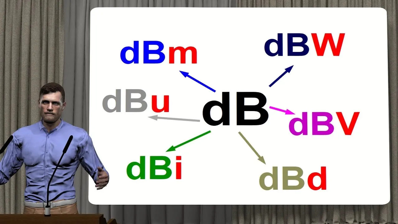
Mathematical proficiency with logarithms and the decibel (dB) unit, which are essential for calculating signal-to-noise ratio and attenuation.
An introductory understanding of physical transmission media, including guided (copper, fiber-optic) and unguided (wireless) channels.
Advanced digital modulation techniques (such as QAM and OFDM) designed to maximize spectral efficiency within Shannon's limits.
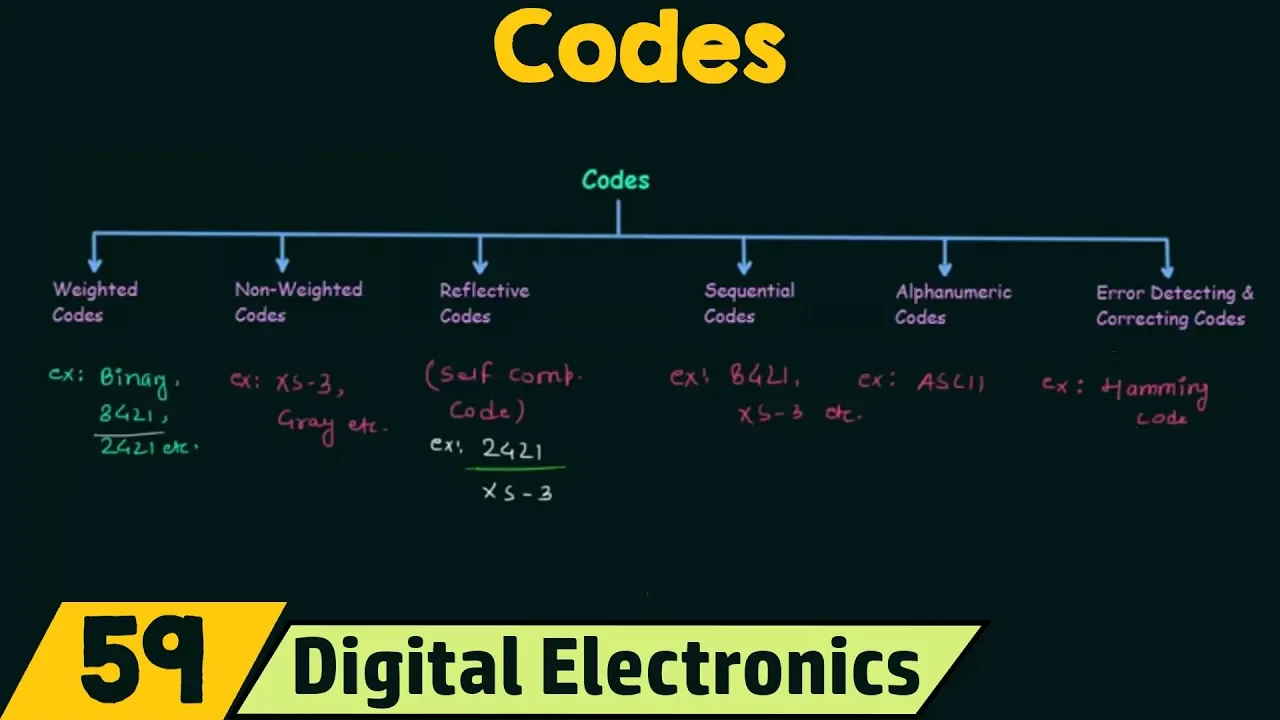
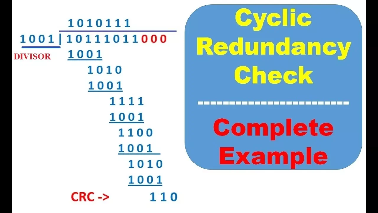
Error detection and correction codes (like CRC, Hamming codes, and LDPC) to handle data corruption caused by transmission impairments.
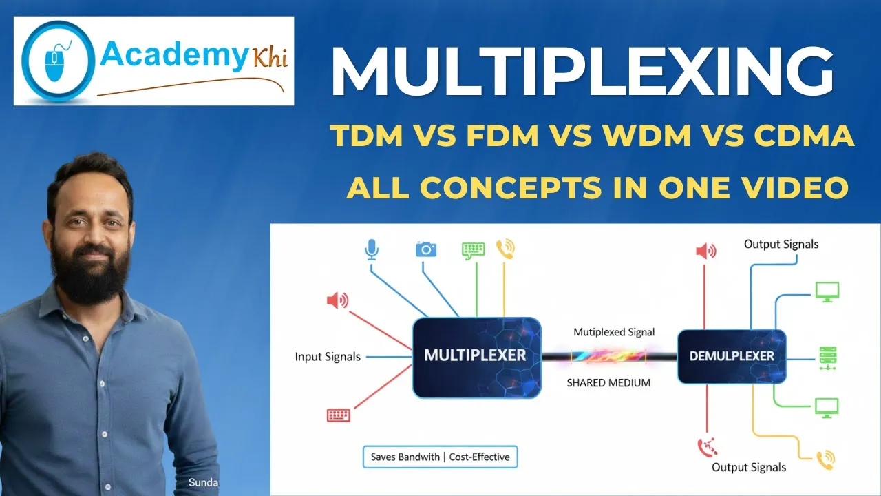
Multiplexing methodologies (FDM, TDM, WDM) used to partition and share the available capacity of a physical channel among multiple signals.
Real-world network design constraints and standards, such as those governing DSL, LTE, 5G, and high-speed Ethernet technologies.
55.5K views137likes57:20Original Release: 2008-10-17
e [Music] [Music] [Music] hello viewers welcome to today's lecture on transmission impairments and channel capacity this is the fourth lecture in the lecture series on data communication on completion of this lecture the students will be able to specify the source of impairments as the signal passes through a channel explain attenuation and unit of attenuation the decibel specify possible distortions of a signal as it passes through the medium explain data rate limits and nqu bit rate because of the bandwidth limitation and then distinguish between bit rate and board rate a new term we shall discuss then identify noise sources finally we shall explain the senon capacity in a noisy Channel that is the maximum bandwidth maximum sign information that can be passed through a noisy channel the topics that I shall cover in this lecture are sources of impairment attenuation and unit of attenuation bandwidth of a medium distortions various kinds of distortions that can take place as the signal passes through a medium data rate limits Nyquist bit rate bit rate and board rate noise sources and finally senon capacity in a noisy Channel as we know to send data you have to convert it into a signal either analog or digital then that signal has to be passed through a medium it can be a simple medium or a complex Communication System whatever it may be the transmitter and receiver will be linked by some medium and unfortunately the medium uh that is that we use is not ideal by that what do we mean normally by ideal we mean whatever is sent by the transmitter should be received by the receiver but because of the limitation of the medium that will not happen there will be some uh uh some impairments which we shall discuss the impairments uh imperfections of the medium cause impairments in the signal what are the possible impairments number one is attenuation Distortion and Noise We Shall discuss each of these impairments one after the other first let us consider attenuation attenuation can be considered as the loss of energy as the signal passes through a medium we know our we know from our basic knowledge of physics as some signal passes through a medium its intensity Falls at the rate of d square distance Square how how how we explain that with the help of suitable unit normally the unit that we use is known as decibel DB here DB is equal to 10 log 10 P2 by P1 where P2 is the power at the destination or point two and P1 is the power at the receiver that is the uh from the at the transmitting end or Point P1 that means power P2 is the received power in the destination P1 is the transmitted power from the source and so this ratio P2 by P1 is taken as the relative measure of the loss of energy and it is expressed as 10 log 10 P2 by P1 and this decides how far the signal can go without amplification from our basic knowledge we know that whenever the signal level is low we can increase the signal level by amplification by a technique known as amplification and whenever we use the amplification obviously the signal level can be raised as shown in this diagram for example this is the point P1 from where the signal is passing and it is going to point P2 and as you can see this was the signal sent and at Point P2 it is very much attenuated now we use an amplifier between 2 and3 and we get Amplified version of the singling so the an amplifier can be used to compensate the attenuation of the medium and as I as I mentioned deciel is a measure of the relative strength of two signals that means signal at the destination and signal at the transmitter if P2 and P1 are signal strength at two different points P2 and one two and one respectively then relative strength at the first point with respect to the second point in DB is as I explained dbal to 10 log 10 P2 by P1 so as you can see here here P1 is the power here P2 is the power and here uh P3 is the power at this point now let let me explain this with the help of an example let the energy strength or power at Point 2 is 1/10th with respect to point1 then attenuation in DB is 10 log 10 1 by 10 that is minus 10 DB it may be noted that the loss of power is represented by a negative sign so we find that whenever the there is attenuation by looking at the sign of the uh that decibel that decibal value we can find out with how much attenuation and also you can identify that it is attenuation on the other hand let the gain as it passes through a through an amplifier is 100 times at 3 with respect to0 2 then the gain in DB is 10 log 10 100 by 1 that is 20 DB in this case as we find this is positive so whenever we amplify then we get a uh value which is positive whenever we whenever attenuation occurs we get a value which is negative now as it passes through uh several points say in other words a channel is in Cascade with an amplifier then maybe another Channel say from here there is another channel so in this way it can be cascaded so what we can do we can add up the values the DV values to find out the final uh attenuation or gain at a point three with respect to one for example in this case say uh the signal strength AT3 with respect to one can be obtained by by adding the attenuation between P1 to P2 then amplification between 2 to 3 so which is equal to - 10 + 20 = 10 DV so here here with respect to 0.1 the the amplification is 10 DB so we find that uh finally from here to here if we consider the it is a gain not attenuation gain of 10 DB so in this way the decal values can be added whenever we have a number of devices or uh channnel in Cascade to find out the final value of attenuation or amplification whatever it may be now uh as we know we are interested in sending data through a medium and we want to send it as fast as possible or in other words we want to send it at a high speed obviously uh we want uh the maximum possible speed but at what speed we can send that will depend on several parameters of the medium what are the parameters of the medium let us see first one is the bandwidth of the channel number of levels used in the signal noise level in the channel so these three factors we shall consider one after the other to understand how first data can be sent through a medium and or Channel and because of these parameters it is restricted first of all let us consider the term bandwidth in the last lecture we have considered the bandwidth of a signal bandwidth what is the bandwidth of a signal bandwidth of a signal is the uh um the the most the signal frequencies where most of the energy lies here it is somewhat different here by bandwidth refers to the range of frequencies that Medium can pass without a loss of 1 half of the power that is minus 3db contained in the signal so you see the bandwidth T is used to refer to the bandwidth of a signal it it also refers to the bandwidth of a channel so whenever we refer to the bandwidth of a signal we refer to the major frequency components on the other hand whenever we refer to a medium we refer we me we mention that what is the range of frequencies that can be sent uh without much attenuation through the channel for example in this case this is the amplitude or we can say uh it can be cons instead of amplitude we can write uh say uh say amplitude and that reflects essentially the attenuation Oran so here we find that uh that the attenuation is less in in this part and on both sides there is higher attenuation that means amplif amplitude is less and and half power is at frequen frequency FL and another half power is at frequency FH so on both sides of this midpoint there is the power level goes down to half uh and so the band WID here for the channel can be considered as FH minus FL L that means fi minus f l so this is the this is how the bandwidth of a channel is represented and as we know uh the frequency components of a digital signal varies from zero to almost Infinity however at higher frequencies the the signal levels are gradually lower and lower and as we know as Digital Signal usually a periodic in nature not periodic in nature and that requires a bandwidth from 0 to Infinity so it needs a low pass Channel low pass means starting from0 to F so you require a channel which will not attenuate starting uh from zero frequency that means DC to almost so we can consider this is somewhat like Infinity a very high frequency if we want to send all the frequency components of a digital signal so bandwidth of a medium decides the quality of the signal at the other end some of the frequency component if we restrict the bandwidth somewhere here some of the frequency component will not reach on the other hand whenever we send analog signal then we can send it through a band pass Channel F1 to F2 but this is the frequency range of a band pass Channel and this band pass channel can be used to send an analog signal because the analog signals have band with like a has within certain range say from lower frequency to Upper frequency later on when we shall discuss various modulation techniques say amplitude frequency and phase modulation we shall see that the these will generate signals having similar to a band that means it can be passed through a band pass Channel and it has other consequences as I mentioned in the last lecture this will help us to send several signals through one channel you can send say one one signal between F1 and F2 another signal between F3 and F4 and so on several signals can be simultaneously sent which we may call frequency Division multiplexing and we shall discuss about it in more detail later on now let us see Distortion let us consider distortion as you have seen one important uh phenomenon that occurs is attenuation apart from attenuation what occurs whenever attenuation occurs we know all frequency components it is assumed that all frequency components are attenuated uniformly however that does not happen in practice it has been found that attenuation of all frequency components are not same some frequenc genes are passed without attenuation some are weakened and some are blocked completely blocked so you can see that uh there are three situations some are passed without attenuation some are weakened and some are blocked this leads to what is known as Distortion that means what the transmitter is sending at the other end of the medium the receiver is not getting the same thing they are not same so in such a situation we can say that signal is distorted or it has suffered Distortion for example this is a input signal and this is the medium through which the signal is being sent and as it sent through the medium the at the other end of the output we find we get output signal which is much different from the input signal and this will be this will be decided by the bandwidth of the channel or medium let me take an example and explain the effect of signal passing through a band limited Channel suppose we are sending a digital signal 0 1 0000 1 0 0 which has bit rate of 2,000 bits per second here the bit rate is 2,000 bits per second BPS this is the 2,000 bits per second signal we are sending so this is the fundamental frequency of the uh Digital Signal obviously apart from 2000 2000 uh fundamental signal it will have the various other harmonics like 3,000 HZ 4,000 HZ 5,000 HZ all the frequencies will be present however they will be up lower and lower amplitude now as we pass this signal through a uh transmission medium having bandwidth of two exactly 200 Heartz we find we get a signal like this so this is this is this is completely different from what was sent it was a rectangular wave what we are getting is a sine wave that means only the fundamental is passing through the medium the other frequency higher frequency components are not passing so here the band width is 2,00 hge that is the bandwidth of the medium now we increase it little bit say to 3,600 hge then we find that signal is somewhat like this that means another harmonic has passed through the medium 3,000 harmonic has passed through the medium we increase the bandwidth to 5,200 some more harmonics have passed we increase the bandwidth to uh say 6800 H we find somewhat very close to uh the original signal but definitely not same now we increase the band to 10,000 hge we find a signal which is very close to the uh original signal and now when the band we is 16,000 Hearts we get a very good quality signal and we can see uh that means this will pass plus up to e harmonic and as a consequence the signal is that we receive at the other end uh through the after passing through the medium will be very close to the original signal that you have sent so with this diagram I have explained how a signal gets distorted as it passes through a band limited Channel now uh apart from attenuation I mean bandwidth limitation there are other kinds of distortion the signal will suffer one of them is known as attenuation Distortion why attenuation Distortion occurs if the attenuation of the medium varies with frequency this leads to attenuation Distortion let us consider let me explain with the help of a voice Grid telephone line suppose let me draw a diagram for a voice Grid telephone line here the a voice Grid telephone line has bandwidth from 0 to maybe uh 4,000 hge this is your 2,000 hge this is your 1,000 and this is your 3,000 and on on this side right we draw the attenuation uh and this is zero say this is minus 10 DB in De and this is+ 10 DB and the uh the the bandwidth of the medium that means the V voice G telephone line in this case is can be represented by uh by like this that means with respect to 100 kiloh it is shown at 100 Kilz it is zero so it will be somewhat like this so we see that uh at at at, hge at, hge it is with respect to th000 hge attenuation is increasing at lower frequencies attenuation is increasing at higher fre frequencies so the higher frequency components will be Attain ated more than the frequencies around this region that means lower frequency component as well as higher frequency components will be attenuated more than this uh central part what is the way out of this how we can overcome this problem this problem can be overcome with the help of a a device known as equalizer so we can put a equalizer to change the characteristic to somewhat like this how say this is the transmitter and this is the medium through which the signal is sent up at the end of the medium we put a hardware known as equalizer and then output of The Equalizer is fed to a receiver now we see that medium and equalizer together is giving a bandwidth like this and obviously in this case whenever the bandwidth is like this then the uh Distortion is much less compared to this one that means this particular bandwidth we get only with equalizer with equalizer so you see uh in in this particular case uh whenever we use equalizer the problem is is less in case of digital signal problem is more in case of analog signal why the reason for that is for digital signal we have seen that the most of the energy is concentrated near the fundamental and lower harmonics at higher harmonics lesser and lesser energies uh present on the other hand an analog signal can have frequency components over the entire range so whenever it is attenuated at some frequency range we get more distortion on on the other hand in case of digital in case of digital signal problem is less sever so that's why this kind of equalizer is used in case of voice gate telephone line to correct the uh bandwidth of the medium and to get a better signal at the receiving end now let us consider another type of distortion that occurs that is known as delay Distortion and this delay Distortion arises particularly in a guided medium not in air later on we shall discuss about the different types of transmission media we shall see that there are two we shall be having two types of transmission media guided and unguided so in whenever the signal is passed through a guided media like twisted pair cable qu shell cable or optical fiber uh it leads to delay Distortion what is delay Distortion delay Distortion arises because velocity of propagation varies with frequency that means the signal components that we are sending will have different velocities for different frequency components as it passes through a guided media and this leads to delay distortion and again let us take up the example of voice Grid telephone line and in this case we consider the delay earlier we considered the attenuation here we considered the delay on this side it is the delay and delay is sa heing from 0 to uh 4,000 micr second and on this side this is the uh frequency that means the hge so 0 to 4,000 that is the bandwidth of the medium now it has been found that uh in the in the middle part in the middle part the velocity is uh velocity delay is less that means velocity is more on either side of the frequency range there is the delay is more or velocity is less so what will happen the lower frequency component will reach later lower or upper frequency component will reach later than the uh middle frequency components that means frequency components in this range will reach earlier than the frequency component in this range and this this range so it may so happen that the a lower and upper frequency component of the previous signal will fall on the uh frequency middle frequency component of the present signal this will lead to Distortion again this can be this effect can be minimized with the help of a of an using an equalizer and The Equalizer after using an equalizer the characteristic can be somewhat like this so this is with equalizer so with with use with with equalizer the bandwidth is much better that means delay Distortion is much less and band with characteristic with respect to delay we find is much better and in this particular case uh digital signal is more affected as we know Digital Signal will be having many high frequency components so uh we find that the delay Distortion affects a Digital Signal more than an analog signal this is opposed to the to that of attenuation Distortion now let us consider the Nyquist bit rate as we have mentioned that the signal that we can send at the other end is dependent on the bandwidth of the channel noise of the channel and because of the of these parameters now let us see in case of a noisess channel we assume that there is no noise although it is not true in practice but for an ideal channel that means without noise the maximum bit rate is given by the nist bit rate and it is explained uh it is equal to C that means nid bit r c is equal 2 into B into log 2 L where C is known as the channel capacity B is the bandwidth of the channel and L is the number of signal levels so we see uh here band we we are taking into consideration and number of signal levels uh we shall explain this uh in detail later on what do we really mean by number of signal levels so it depends on the three parameters rather two parameters in this case the channel capacity depends on bwick and the number of signal levels that we are s sending actually uh to understand the number of signal levels another parameter known as board rate has to be understood let us see what do we really mean by board rate the board rate of a signal is or the signaling rate is the is defined as the number of distinct symbols transmitted per second respective respective of the form of encoding we know whenever we are sending a digital signal we know the bit rate and bit interval now in a single bit interval it is possible to send a the number of the number of distinct symbols that can be transmitted per second actually will depend on how much you are sending within the bit interval if in a bit interval multiple levels can be sent then we can send more information for example in case of best band digital transmission where the number of levels is two that means within a bit interval we can send either zero we know that either Z Volt or 1 volt so we have got two distinct values or two levels zero level and one level so in this case it is two now suppose it is possible to send 0 volt 0.5 volt uh 1 volt and uh then uh 2 volt like that say let's take these four values we can send 0.5 1 and two so in this case number of levels is not two but four that means within a bit period that means within that bit period we can send one of the four value 0 vol5 volt 1 Volt or 2 volt in that case that L will be equal to four so depending on how many levels are present uh the maximum board rate will be dependent on that so for digital transmission as we know uh it is equal to 1 by element width in second that is equal to 2B because here L is equal to 2 so this is the case for digital transmission with only two levels the bat rate or information rate is is is the is actual equivalent number of bits transmitted per second that means this allows us F we are able to put more number of levels within a particular bit rate particular bit interval then we can send more information for a given bandwidth for example uh uh the bit rate or information rate is the actual equivalent number of bits uh transmitted per second that means I is equal to board rate into bits per second board rate means the number of possible values that we can send and bit rate is actually the number of bits we are sending bits per Bard so Bard rate into n or Bard rate into log 2 m so here m is the number of levels so we find that for binary encoding the bit rate and The Bard rate are same because here the value of m equal to two so log 2 is essentially m one so that means the information rate or bit rate is same as the board rate so information rate is same as the board rate in case of and binary encoding or digital encoding but for maximal use of the channel we can use multi-level encoding that will allow us to send more information to send to a communication medium let me consider an example of the telephone channel that we have already discussed having bandwidth is equal to 4 khz assuming that there is no noise determine the channel capacity for the following encoding levels say we are considering encoding level two and encoding level 128 so when the encoding level two we get uh the uh Channel capacity equal to 2B that means 8 kilobits per seconds or we can write it as kbps on the other hand when we are using one 128 different levels for encoding later on we shall discuss in details how multi-level encoding can be done then we can send 2 into 4 4,000 that is the bandwidth into log to 128 that means it gives us 8,000 into 7 or 56 kilobit per second that means kbps 56 kilobit per second so you see by suitable encoding multi-level encoding uh through a uh Channel having bandwidth of only 4 Kilz we can send a very high data rate 56 kilobits per second that is precisely what is done in case of modem modem can send 56 kilobits per second Maxim that is the maximum B data rate so we find that uh this is the this is how we can send more information so far we have neglected the effect of noise but ideally that will not be so a channel will always have some noise so when there is noise present in a medium the limitations of both bandwidth and noise must be taken into consideration so far we have only taken into consideration the limitation due to bandwidth now let us take the limitation due to uh the due to the noise why a noise Spike may cause a given level to be interpreted as a signal of Greater level if it is uh in positive phase or a smaller level if it is a negative phase that means suppose you are sending a voltage level5 volt and there is a noise of plus5 volt that will make the signal level equal to 1 volt although.5 volt was sent now we are receiving 1 VT at the receiving end and so the at the receiving end it will be interpreted as a signal of different level so it will be we shall get incorrect data on the other hand if it is negative phase say plus five and the receive signal say noise is minus 5 volt then they together it will make it Z volt so we we shall be getting another uh signal level so which is also incorrect so in this way the uh the because of Noise We may not get correct data particularly noise becomes more problematic as the number of levels increases so if we have only two levels 0 and one which is represented by 0 volt and plus 5 volt then problem is less we can tolerate up to maybe plusus 2 volt of noise on the other hand when we are using say four levels we divide 5 volt into four equal parts there it will be more susceptible to noise or if we increase if the noise level the number of level is 128 then we can see that say 0 to 5 volt is divided into 128 different values and if a small noise will change the uh the transmitted noise level uh uh and so at the receiving end we shall get a incorrect voltage level signal level and so it becomes more problematic as the number of levels increases to uh quantize to uh quantify the noise level a parameter known as signal to noise ratio use let p is the average signal power and N is the average noise power then signal to noise is equal to average signal Power by average noise power P byn then signal to noise ratio in decel is represented by 10 log s byn so in decibel this is the uh signal to noise ratio now for a given signal to noise ratio the sonon capacity for his noisy Channel gives the highest data rate uh represented by c equal to B bandwidth is there bandwidth part is there and also it it takes into consider consideration the signal to noise ratio so the sonon capacity gives the capacity equal to B into log to 1+ S byn where s byn is the signal to noise ratio so we find that in case of extremely noisy Channel c equal to 0 that means log 2 1 equal to 0 that means whenever we try to send data through a very noisy Channel irrespective of its bandwidth we may not get any we may not be able to send any data because of uh this fact that means if the signal noise level is uh very high compared to the signal level then we cannot send any data through it that means Channel capacity is zero now we have two different parameters one is Nyquist bit rate which does not uh which gives us a channel capacity based on bandwidth and number of levels that we use for encoding another is based on bandwidth and the signal to noise ratio so we have to actually uh between the Nyquist bit rate and the sonon limit the result providing the smallest Channel capacity is the one that establishes the limit that means we may compute the Nyquist bit rate and senon capacity and find out which one is the lower and the lower one has to be taken as the channel capacity or the maximum information that can be sent to the midd to the medium uh let me take few examples here uh in particularly in case of noisy channel so here the channel has got bandwidth of 4 KZ as as earlier and determine the channel capacity for each of the following signal to noise ratios 20 DB 30 DB and 40 DB so we find 20 DB is essentially 100 signal to noise ratio so it gives you uh a channel capacity of 26 Point sonon capacity essentially gives is equal to 26.6 KOB per second for uh 30 DB it is actually signal to noise ratio of th000 it gives you a uh Channel capacity of 39.8 kilobit per second and for signal to noise ratio of 40db uh we get a channel capacity of 53.1 kilobits per second so you see the uh as the signal to noise ratio is higher and higher we can achieve higher Channel capacity we get higher Channel capacity for higher value of signal to noise ratio now let us consider a situation where we have got a Channel with a bandwidth of 4 khz a signal to noise ratio of 30 DB so we have to determine maximum information rate for four level encoding so here the value of M is four so we are using four level encoding So based on our uh Nyquist bit rate we can calculate the value for B is equal to 4 and four level encoding we get 16 uh kilobits per second that means 2 into b a 8 into log 2 log 2 4 that means we get 2 so 2 into 4 into 2 we get 16 kilobit per second on the other hand by if we take into consideration the signal to noise ratio of 30 DB then we get uh sonon capacity of 39.8 kilobit per second so we find two values one value is 39.8 kilobit per second that is the maximum uh capacity that is possible however with full level of encoding we can achieve only 16 kilobits per second so smallest of the two values has to be taken as the information capacity so in this particular case when we are using Bal to 4 khz signal to noise ratio of 30 DB uh then and using full level that means based on these three values full level encoding the information capacity will be equal to 16 kilobit per second so in this way we can find out what is the information capacity in a particular situation let us take another example here a channel has bandwidth b equal to 4 khz signal to noise ratio of 30 DB and we would like to find out the maximum information rate for 128 level encoding so so here the nist bit rate is uh based on nist bit rate Bal to 4 and m equal to 120 levels we get 56 kilobit per second on the other hand because of the signal to noise ratio of 30 DB we get sonon capacity of 39.8 so here we see we are using uh a large number of levels 128 which may provide us 56 kilobit per second but because of the the lower signal to noise ratio the uh information capacity will be restricted to 39.8 so you won't get 56 kilobit per second but we shall get 39.8 kilobit per second so you see the smallest of the two here we have to take so here it is limited by the signal to noise ratio in the previous case it was limited by the uh uh limited by the uh the Nyquist bit rate now we can consider another example say the the digital signal is to be designed to permit 160 kilobits per second that means we have to send 160 kilobits per second for a bandwidth of 20 khz determine the number of levels and signal to noise ratio so here the problem is given in a little different way here the the uh band weight is given band weight is given 20 khz and our desired data rate is given you have to find out the number of levels and signal tation so applying Nyquist bit rate to determine the number of levels we get Cal to 2 B log 2 m so you get uh 16 that means four bits per board that means a single signal element has to represent 4 bits so that the number of levels is 16 applying senon capacity we get signal to noise ratio based on this formula 20 uh 4.07 so you see the uh with signal to noise ratio of 24.7 and uh number of levels equal to 16 we can achieve 16 160 kilobits per second data transmission uh through a a Channel having bandwidth of 20 khz so this examples tells us how we can design a transmission system to provide suitable number of encoding levels and to and a suitable value of signal to noise ratio so that we can achieve a uh desired data rate I believe our discussion will not be complete if we don't discuss about the types of noise that is present in the medium uh there are several types of noise that may corrupt a signal and the most common noise types are discussed here first one is thermal noise what is thermal noise uh normally if we look at a conductor a copper where apparently we find everything it is very calm and cool there is no movement nothing is taking place however if you look at the molecular level we know each molecule is vibrating and uh within with is vibrating within the range and all the free electrons are moving around the conductor so there is lot of movements and this leads to noise because of the movement of the electrons which are responsible for conducting current we are getting some noise and this is know known as the thermal noise and this thermal noise is dependent on three parameters where K the parameter K is the busman's constant T is the temperature absolute temperature in Kelvin and B is the bandwidth of the channel so uh we can see higher the bandwidth higher is the noise so n is equal to KTB and another very important point that you must notice this thermal noise increases with temperature as the temperature increases more and more noise increases and that is the reason why you will observe that during summer the quality of signal that we receive is poorer than in Winter then the second type of noise is known as inter modulation inter modulation occurs when signals of different frequencies share the same medium suppose a medium is sharing a frequency F1 it is also sharing a frequency F2 now because these two signals are present due to nonar linearities in the transmission system it may generate signal like fub1 plus F2 this signal fub1 + F2 will add if it is in the same phase if there is a signal of fub1 plus F2 in the original signal that means the noise generated because of incon modulation will be added to the signal if it is having a frequency component fub1 plus FS2 so we find that this inter modulation occurs when signals of different frequencies share the same medium this is an example how a different frequenc signal component is generated from two frequency compon components then the third type of noise that we commonly encounter is known as cross talk this cross talk is due to unwanted coupling between two media uh whenever uh for example you will later in the next class we shall discuss the various types of transmission media there will see particularly in telephon and many other applications a number of cables are bunched together and send from one place to another so whenever we are sending a number of cables side by side the signal passing through one cable induces signal in other cable and this leads to cross talk in our telephone Network the cross talk is a daily phenomenon we have seen that in telephone Network we very we frequently encounter cross talk we hear some un unwanted talk going on in the background this is because of this unwanted coupling between two uh transmission media that means cables finally the impulse noise this arises due to disturbances such as lightning and electrical Sparks this is not uh this is not getting generated in the medium but the environment is generating it for example in the Rus season there is lightning or in an industrial environment there is there are electrical spars welding turning on and turning off of switches various types of things can occur that leads to uh Electro radiation of electromag magnetic signals and that may corrupt the the uh signal that is passing through the medium and this affects more severely the digital signal not the analog signal that much because a zero may become one or a one may become zero if it is a digital signal on the other hand in case of analog signal it will not affect much signal level will possibly change if it is if we are listening to voice you will hear some disturbances but that error is tolerable but in digital domain this error uh will lead to uh Corruption of data so uh with this we complete our discussion on the transmission impairments and channel capacity because of the reations of the channel let us give some review questions which will be answered in the next next lecture question number one let the energy strength at Point 2 is 1550th with respect to 01 find out the attenuation in DB uh for 0.1 with respect to point 2 assuming there is no noise determine Channel capacity for the encoding level four uh encoding level four and bandwidth is equal to 4 KZ a channel capacity has bandwidth of 10 MHz determine Channel capacity for each of the signal to noise for uh okay this need not be here for the for the this part should not for the signal to noise ratio of 60 DB the digital sign the fourth question is the digital signal is to be designed to permit 56 kilobit per second for a bandwidth of 4 k determine the number of levels required and the signal to noise ratio these are the four questions you have to answer and answer will be given in the next lecture and here is the answer of the previous lecture distinguish between data and Signal data is essentially an entity entity which conveys some meaning on the other hand the signal is the representation of data in some electric electromagnetic and Optical form so so whenever data needs to be sent it has to be converted to Signal of some form for transmission over a suitable medium second question was what are the three parameters that characterize a periodic signal as we know the three parameters are amplitude frequency and phase and amplitude is represented by a frequency is represented by F and phase is represented by five third question was distinguish between time domain and frequency representation of a signal whenever a signal is represented as a function of time it is called time domain representation an electromagnetic signal can be either continuous or discret it is represented by St whenever a signal is represented as a function of frequency it is called frequency domain representation it is expressed in different in terms of different frequency components and represented by ASF and the fourth question was what equipments are used to visualize uh electronic signals in time domain and frequency domain for frequency time domain representation we use cathod oscilloscope and for frequency domain representation we use Spectrum analyzer finally the last question was what is the round trip propagation time between Earth and and is your stationary satellite as we know distance is 36,000 km and speed of life light is 3 into 10^ 8 m/s so from that we get a uh propagation time of 0.24 second so we find the round TP propagation delay is about quarter of a second it's a long time later on we shall discuss about it more for the time being thank you
Up Next

7:16
Inside a Wind Turbine: Engineering and Renewable Energy Explained
@fredolsenrenewables
1.1M views•2011-11-22

12:54
Triumph of Orthodoxy Icon: Byzantine Art & History Explained
@BenCallan
2.1K views•2024-08-06
44:26
The New Bauhaus: Chicago's Design Legacy and Impact
@IITInstituteofDesign
511 views•2019-10-22

1:42
Game of Thrones Opening Credits: A Cinematic Analysis
@gameofthrones
46.3M views•2011-04-18
Related Study Plans & Knowledge Roadmaps
Structured learning paths in General & Interdisciplinary Studies
general-studies
Elevator Engineering: History, Physics & Cities
01From Hoists to Safety Brakes: The Dawn of Vertical Lift
02Hydraulic vs. Traction: The Engineering Physics of Elevators
03Modern Speed, Safety, and Algorithms
+ 2 more learning modules
12h5 modules
Explore Roadmap
general-studies
Rubber: Material Science, History & Geopolitics
01Origins of Natural Rubber & Mesoamerican History
02The Chemistry of Natural Rubber & Vulcanization
03The Geopolitics of the Rubber Boom & Colonization
+ 2 more learning modules
12h5 modules
Explore Roadmap
general-studies
Containerization: Evolution, Logistics & Trade
01Ancient Trade & Bulk Cargo: Amphorae to Barrels
02The Industrial Revolution & Cardboard Packaging
03The Containerization Revolution: Malcom McLean
+ 2 more learning modules
12h5 modules
Explore Roadmap
general-studies
Textile Tech: Evolution, Labor & Global Impact
01Pre-Industrial Textiles: Handloom & Cottage Industry
02Mechanization: The Spinning Jenny to the Power Loom
03The Factory System & Global Labor Transformation
+ 2 more learning modules
10h5 modules
Explore Roadmap