When selecting bearings, consider four key factors: (1) Bore type - choose round bore for standard shafts or hex bore for hexagonal shafts; (2) Flange presence - flanged bearings locate themselves in holes but cost more, while non-flanged bearings require bottomed holes and are cheaper; (3) Protection type - open bearings save space but need clean environments, while shielded bearings handle higher RPMs and sealed bearings tolerate misalignment better; (4) Application requirements - sealed bearings excel in gearboxes with potential misalignment, while shielded bearings suit high-speed applications.
Bearing Selection Guide: Bore, Flange, Seal, and Shield Types
Added:Deep Dive
Fundamental concepts of rotational motion, friction, and the primary purpose of bearings in mechanical systems.

Por que essa Pequena Peça Que Pode Destruir Qualquer Máquina
321
Every mechanical system with rotation faces a fundamental problem: when a shaft rotates within a fixed housing, friction occurs. This friction generates heat, wear, and energy loss. Bearings exist to solve this exact problem by replacing sliding friction with rolling friction, which is significantly smaller and more controllable. A conventional ball bearing consists of four main components: the outer ring (fixed in the housing), the inner ring (rotates with the shaft), the rolling elements (balls or rollers between the rings that enable movement with minimal friction), and the cage (which keeps the rolling elements evenly spaced to prevent unnecessary contact and wear).
Click to watch →
1 Introduction to bearingمقدمة مختصرة عن الرولمان بلى
102.5K
Bearings are essential components in rotating equipment that support shafts, reduce friction, and enable efficient power transmission. Friction occurs between moving surfaces and exists in two forms: sliding friction (surfaces sliding across each other, creating resistance and heat) and rolling friction (surfaces rolling over each other, producing less friction). Three main types of mechanical motion exist: rotational motion (shaft rotating around its axis), linear motion (movement in a straight line), and angular motion (movement in multiple directions except one). Understanding these fundamentals is crucial for selecting appropriate bearings in mechanical systems.
Click to watch →

Bearing || Mechanical Engineering || Lecture 66 || Mechanical by Gaurav Sir
178
Bearings are mechanical components used to support rotating shafts and enable smooth rotational motion. They are installed at both ends of rotating shafts in machines like bicycles, motorcycles, and flour mills. The primary purpose of bearings is to provide smooth motion, minimize friction between moving parts, and prevent unwanted vibrations. Without bearings, shafts would develop wear, deformation, and premature failure due to increased friction and vibration.
Click to watch →

RODAMIENTOS
132
The primary purpose of bearings is to prevent direct metal-to-metal contact between moving parts, which reduces friction, heat generation, and wear. Bearings also reduce energy consumption by replacing sliding friction with rolling friction. They transmit loads from rotating elements to the housing, which can be radial, axial, or a combination of both. The principle of rolling friction being lower than sliding friction is fundamental to bearing operation, enabling efficient movement of rotating components.
Click to watch →

KTU S1 Question Paper Hacked | Intro to Mechanical & Civil Engineering | Zero to Infinity | Part 01
3.1K
The primary functions of bearings in rotating systems are: (1) to reduce friction between moving parts, and (2) to support and carry loads. Bearings allow smooth rotation while minimizing energy losses due to friction.
Click to watch →
Deep Dive
Understanding the difference between radial, axial (thrust), and combined loads in structural or machine design.
Bearing Load Types Explained (Hindi) | Radial, Axial & Combined Load Practical Demo
460
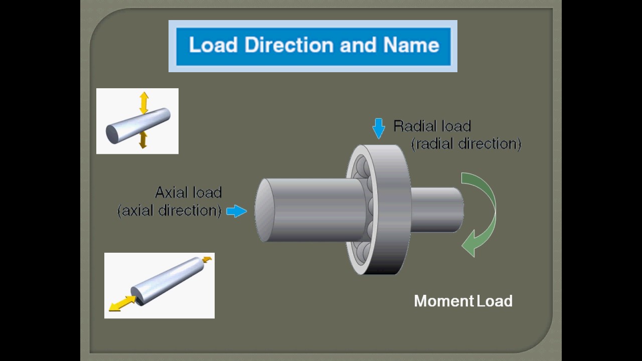
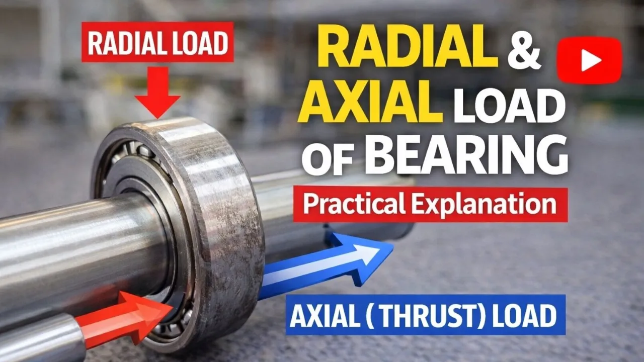
Bearings experience three primary types of loads: radial load (perpendicular to the shaft axis, pushing the shaft sideways), axial/thrust load (parallel to the shaft axis, pushing the shaft forward or backward), and combined load (both radial and axial loads acting simultaneously). Understanding which load type is applied to a bearing is crucial for proper bearing selection, as selecting an inappropriate bearing for the load conditions increases the risk of bearing failure. For high radial loads, needle roller bearings are suitable; for axial loads, thrust bearings are recommended; and for combined loads, angular contact ball bearings are preferred.
Click to watch →
Combined Radial and Thrust Loading | Bearings | Machine Design | L5.2 (Urdu/Hindi)
970
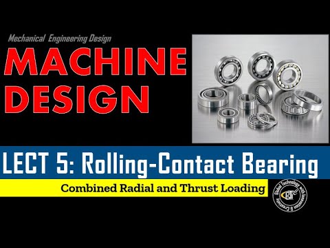
When bearings experience both radial and axial loads simultaneously, the equivalent load must be calculated using the formula P = X × V × Fr + Y × Fa, where V is the rotation factor (1 when inner ring rotates, 1.2 when outer ring rotates), and X and Y are factors determined from bearing tables based on the ratio of axial load to static load rating (Fa/C0). The L10 life is then calculated using the formula L10 = (C10/P)^3 × 10^6 revolutions, where C10 is the basic dynamic load rating and P is the equivalent load.
Click to watch →
🔧 Tipos de CARGAS en RODAMIENTOS (Radial, Axial y Combinada) | Explicado Fácil
2K
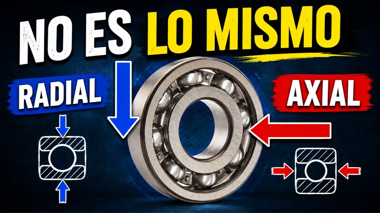
Bearings in mechanical systems experience three fundamental types of loads: radial load acts perpendicular to the shaft axis (pushing the bearing from the sides), axial load acts parallel to the shaft axis (pushing or pulling along the length of the shaft), and combined load occurs when both radial and axial forces act simultaneously on the bearing.
Click to watch →
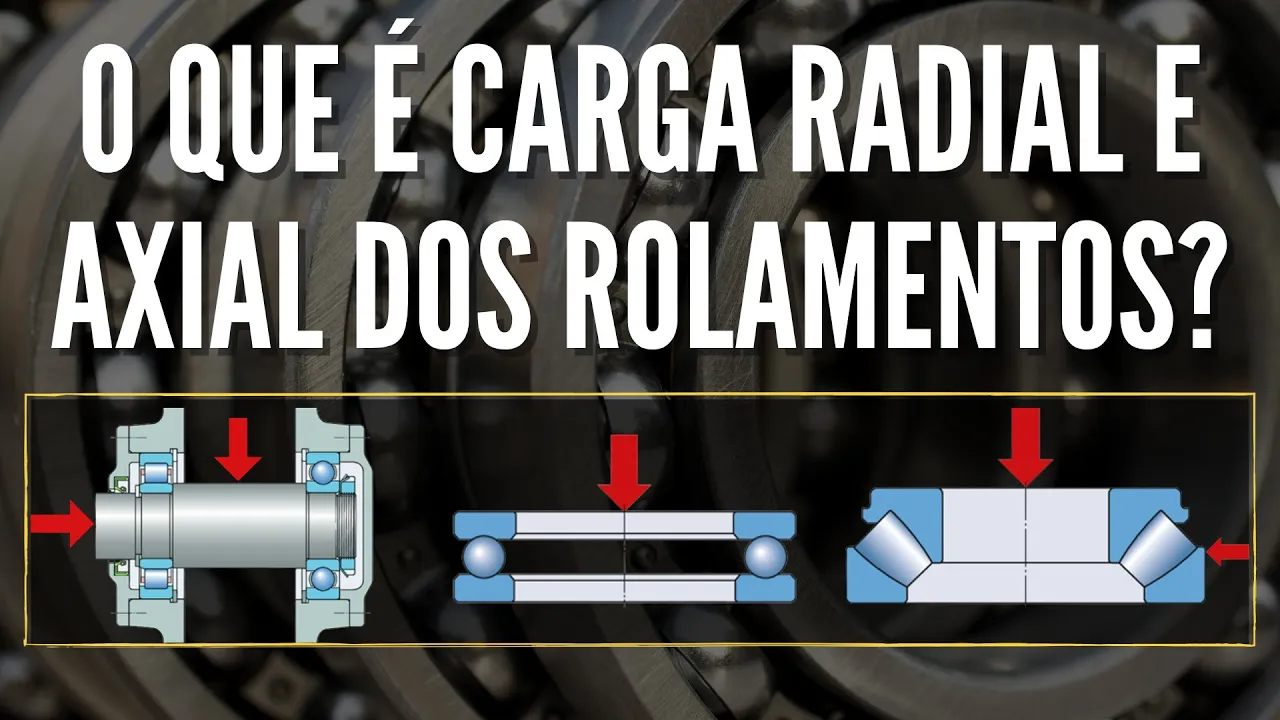
Carga radial e axial: qual a diferença entre elas?
28K
Radial loads act perpendicular to the axis of rotation (like pulling a rope toward the center), while axial loads act parallel to the axis (like pushing along the length of the shaft); bearing selection depends on identifying the load direction, as radial bearings support perpendicular loads but may fail under high axial loads, axial bearings support parallel loads, and combined load bearings like conical bearings can handle both simultaneously.
Click to watch →

Mechanotechnics N4 Bearings - Loading acting on Shafts Introduction @mathszoneafricanmotives
6.8K
Radial load is a force perpendicular to the shaft axis, acting at 90 degrees and associated with rotation only. Axial load (thrust) is a force parallel to the shaft axis, which can be in push or pull direction. These are the two primary load types that bearings must accommodate. Understanding the direction and nature of these loads is fundamental to bearing selection and analysis.
Click to watch →
Deep Dive
Basic knowledge of engineering tolerances, fits (e.g., clearance, interference), and shaft/housing dimensioning.

🔩 TOLERANCIA DIMENSIONAL | Tipos de Ajustes, Cálculo y Selección | IMPORTANCIA DE LA TOLERANCIA
220.8K
Dimensional tolerances define acceptable variations in part dimensions to ensure functional assembly while balancing manufacturing costs; the ISO 286 standard establishes 20 tolerance grades (IT01 to IT18) that depend on both the nominal dimension and required precision level, with tolerance positions (indicated by letters like H for holes and h for shafts) determining whether a fit will be clearance, interference, or transition based on how the tolerance intervals overlap between mating parts.
Click to watch →

लिमिट फिट्स और टोलरेंस:Limit Fits & Tolerances
48.2K
Tolerance is the permissible variation in a dimension, calculated as the difference between upper and lower limits (e.g., 50 ± 0.02 mm has upper limit 50.02 mm and lower limit 49.98 mm). Clearance is the uniform difference between mating surfaces, which can be positive or negative. Fits describe the relationship between hole and shaft: Clearance Fit (positive difference, e.g., H8 for loose running fit), Transition Fit (between clearance and interference, e.g., H7/k6 for push fit), and Interference Fit (negative difference, e.g., H7/p6 for press fit). Hole basis system uses capital letters (H) for hole reference, while shaft basis uses lowercase letters (h) for shaft reference.
Click to watch →
#fitter || #dieselmechanic || ALP CBT-2 TRADE || LIMIT FITS & TOLERANCES || Er. S K Jha Sir
61.6K
This video explains fundamental concepts of limit fits and tolerances in mechanical engineering, covering key topics including nominal size (basic size), actual size, tolerance (sahiṣṇutā), deviation, clearance fit, interference fit, and transition fit. The instructor explains hole basis system (where hole size remains constant) and shaft basis system (where shaft size remains constant), along with fundamental deviation symbols (uppercase letters for holes, lowercase for shafts). The video also covers BIS standards (450 hole and shaft sizes), BS standards (21 sizes), and ISO standards (28 sizes), and explains how to calculate tolerance by subtracting lower limit from upper limit.
Click to watch →

Numerical problems on fit and tolerances
124.7K
This comprehensive section covers the foundational concepts of mechanical fits and dimensional analysis essential for engineering design. It begins with three fundamental fit types: clearance fit (minimum hole > maximum shaft), interference fit (minimum shaft > maximum hole), and transition fit (overlapping tolerance zones). Allowance is calculated as the difference between maximum metal limits. The hole basis system sets hole deviation to zero, while the shaft basis system sets shaft deviation to zero. Practical examples demonstrate calculations for basic sizes of 50mm, 80mm, and 15mm, showing how to determine appropriate dimensions for achieving specified allowances and fits. The section then transitions to ANSI B4.2 preferred fits, explaining how letter designations (H11, H9, H8, H7, H6 for holes; C11, D9, F7, G6, H6, J6, K6, M6, N6, P6, R6, S6, T6, U6, V6, X6, Y6, Z6, ZA6, ZB6, ZC6 for shafts) determine fit characteristics. Clearance fits use shafts A-H; transition fits use J-P; interference fits use R-ZC. The International Tolerance (IT) grading system is introduced, explaining how lower IT numbers (IT5-IT7) require precise machining (lapping, honing, grinding) and higher costs, while higher numbers (IT8-IT10) allow less precise processes (boring, milling) and lower costs. IT01-IT6 serve gauges and instruments; IT5-IT12 serve bearings and general engineering.
Click to watch →
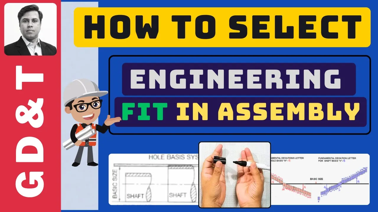
How to choose Engineering Fit | LIMIT, FIT & TOLERANCE
50.6K
Engineering fits describe the relationship between mating parts (shaft and hole) based on size differences before assembly, categorized into clearance fit (always positive clearance), interference fit (always negative clearance requiring force/heat), and transition fit (may result in either clearance or interference); the selection involves understanding tolerance (difference between upper and lower size limits), allowance (worst-case clearance), and fundamental deviation (deviation closest to the zero line), with two main systems: hole basis system (hole size constant, shaft sizes vary) and shaft basis system (shaft size constant, hole sizes vary).
Click to watch →
Deep Dive
Awareness of environmental factors in mechanical design, such as dust, moisture, and temperature, and the general need for lubrication.
Machine Design | Mechanical Engineering | IIMT College of Polytechnic , Greater Noida
146
A good designer must have good environmental knowledge. Designs must consider environmental factors such as rain, temperature changes, and humidity. For example, if a design allows water to enter and cause rust, or if temperature changes affect the work, the design must account for these environmental conditions.
Click to watch →

ULTRASOUND WITH CHRIS HULLUM - UE SYSTEMS
133
Environmental conditions have a huge impact on lubrication requirements. Vertically mounted motors have different lubrication needs than horizontally mounted ones. Speed, load, humidity, temperature, and dust all affect how much lubrication a bearing needs. Organizations must consider these environmental factors when determining lubrication strategies.
Click to watch →

Implementando Lubricación Centrada en Confiabilidad
21K
There are five main enemies of lubrication that work together to destroy machinery: (1) Moisture/Water (El Mojado) - enters lubricant and causes damage; (2) Particles (El Destructor) - harmful elements that enter with lubricant or through the work process, causing abrasion and erosion; (3) Temperature (Mr. Heat) - reduces lubricant viscosity, shortens useful life, decreases oxidation resistance, and combines with water and particles to cause more damage; (4) Air/Bubbles (Sexy Bubbles) - causes foaming, trapped air, increased oxidation rates, cavitation, and improper hydraulic system operation; (5) Chemicals (Doctor Kimi) - various substances like glycol, fuel, acids, or process products that destroy lubricant directly.
Click to watch →

Introducción al diseño mecánico: consideraciones principales || Diseño en Ingeniería Mecánica
2.8K
Mechanical design involves multiple interconnected considerations: (1) Functionality - whether the component performs its intended purpose; (2) Strength/Resistance - ensuring the element can withstand applied loads; (3) Rigidity/Stiffness - controlling deformation under load; (4) Wear - predicting degradation during service life; (5) Environmental Effects - corrosion and other environmental impacts; (6) Safety Factor - margin between expected stress and material strength; (7) Reliability - probability of failure-free operation; (8) Manufacturability - ease of production; (9) Cost - economic factors; (10) Friction - coefficient affecting efficiency; (11) Weight - critical in transportation applications; (12) Service Life - durability expectations; (13) Noise - acoustic considerations; (14) Aesthetics - form and style; (15) Size - dimensional constraints; (16) Thermal Properties - heat transfer behavior; (17) Surface Finish - quality requirements; (18) Lubrication - maintenance considerations; (19) Marketability - commercial viability; (20) Maintenance Requirements - serviceability; (21) Volume - spatial constraints; (22) Legal Responsibility - liability concerns; (23) Recyclability - environmental impact.
Click to watch →

Mechanical Design II - Journal Bearings Stable Lubrication + Example M4P2
338
The Sommerfeld number (S = (R/c)² × μn/P) is a dimensionless parameter used to analyze journal bearings by combining radial clearance ratio and bearing characteristic number, enabling engineers to use standardized charts to determine performance metrics like minimum film thickness, friction coefficient, and power loss. Stable lubrication (thick film) requires maintaining μn/P ≥ 1.7 × 10⁻⁶ to ensure predictable friction behavior and prevent metal-to-metal contact; below this threshold, unstable thin-film lubrication causes erratic friction increases. In practice, engineers calculate the Sommerfeld number using bearing geometry, load, speed, and viscosity, then consult Rundin charts for specific L/D ratios to find required parameters such as minimum film thickness (h₀ = y × c), friction factor (f), and flow rates (Q and Qs).
Click to watch →
Prerequisite Knowledge
- Concept 01Fundamental concepts of rotational motion, friction, and the primary purpose of bearings in mechanical systems.
- Concept 02Understanding the difference between radial, axial (thrust), and combined loads in structural or machine design.
- Concept 03Basic knowledge of engineering tolerances, fits (e.g., clearance, interference), and shaft/housing dimensioning.
- Concept 04Awareness of environmental factors in mechanical design, such as dust, moisture, and temperature, and the general need for lubrication.
Subsequent Learning
- Step 01Calculating bearing fatigue life and dynamic/static load ratings using standardized formulas (such as ISO L10 life).
- Step 02Advanced lubrication engineering, including selecting the right grease or oil viscosity and determining relubrication intervals based on speed and temperature.
- Step 03Analyzing bearing failure modes (such as spalling, brinelling, and electrical erosion) to diagnose mechanical issues in the field.
- Step 04Precision mounting and dismounting techniques, including thermal expansion assembly and the use of specialized installation tools.
- Step 05Integrating bearings into 3D CAD modeling and performing finite element analysis (FEA) on shaft-bearing-housing assemblies.
Bearing Basics
Shield vs Seal
Bearing Basics
0:00Playing Section
- 1
Identify bearing by bore size: round or hex.
- 2
Flange locates depth in through holes; non-flange is cheaper.
Tribology-First and Non-Contact System Design
While standard guides focus on selecting discrete rolling-element bearings using physical attributes like bore size, flanges, seals, and shields, a major counter-perspective in high-performance engineering advocates for a 'Tribology-First' or 'Non-Contact' approach. This viewpoint argues that traditional component-level selection is outdated and prone to failure under complex dynamic loads. Instead of choosing physical barriers like seals or shields—which introduce friction, heat, and wear limits—modern design increasingly leverages active magnetic levitation, air bearings, or fluid-film lubrication. By eliminating physical contact, these alternative technologies render traditional selection criteria (like shields and physical seals) obsolete, offering near-zero friction, virtually infinite operating life, and no lubrication maintenance. Additionally, reliability engineers argue that bearing selection should be driven by dynamic digital-twin simulations of the entire system's thermal and chemical environment, rather than relying on static catalog dimensions and standard physical configurations.
Deep Dive
Calculating bearing fatigue life and dynamic/static load ratings using standardized formulas (such as ISO L10 life).

Bearing Size Calculation | Basic Rating Life L10 Calculation
44.1K
The bearing basic rating life L10 is calculated using the formula L10 = (C/P)^p, where C is the basic dynamic load rating, P is the equivalent dynamic load, and p is 3 for ball bearings or 10/3 for roller bearings; this statistical formula predicts the life at which 90% of bearings will survive under normal operating conditions (constant load, appropriate speed, and full film lubrication), and the calculated life must meet or exceed the recommended life for the specific machine type and duty cycle.
Click to watch →

DTS | One Shot Unit 3 | Rolling Contact Bearings.
1.4K
Bearing life is total revolutions before fatigue failure, categorized into hours and millions of revolutions. L10 is rating life where 90% of bearings complete before first crack (90% reliability). L50 is median life where 50% complete before failure. L10H converts L10 to hours: L10H = (L10 * 60 * n) / 10^6. Basic static capacity (CO) is load when shaft is stationary. Basic dynamic capacity (C) is load for 1 million revolutions. Equivalent dynamic load PE = X * V * FR + Y * FA combines radial and axial loads. For roller bearings, L10 = (C/PE)^(10/3). Default values: X=1, Y=1, V=1 if not specified. These parameters guide bearing selection for rotating applications.
Click to watch →
9.2 Подшипники качения
10.8K
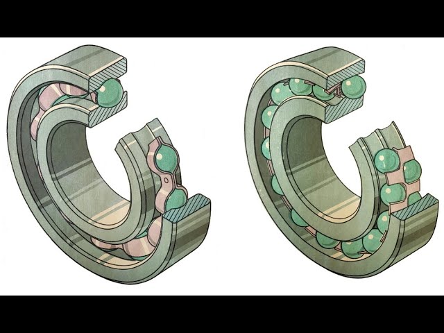
Rolling bearings are rated by dynamic load rating (C)—the constant radial load a bearing can withstand for one million revolutions without fatigue pitting in 90% of bearings—and static load rating (C₀)—the maximum load a stationary bearing can withstand without permanent deformation. The dynamic rating is always higher than the static rating. The equivalent dynamic load converts actual variable loads (combined radial and axial) into a single equivalent load for life calculation. This conversion uses load factors X and Y from manufacturer tables, which depend on the ratio of axial to radial load. The equivalent load formula accounts for shock and vibration factors (K_b) and temperature effects (K_t). Life calculation uses the formula L = (C/P)^p × L₁₀, where p is 3 for ball bearings and 10/3 for roller bearings.
Click to watch →

RULMANLAR
7.2K
Bearing selection depends on dimensions, load type, speed, temperature, environment, and maintenance requirements. Load ratings include dynamic load rating (C) for 1 million revolutions and static load rating (C0) for permanent deformation. Bearing life is calculated using L10 = (C/P)^3 × 10^6 revolutions. Life is highly sensitive to load (doubling load reduces life to 1/8th) and speed (doubling speed halves life).
Click to watch →

Machine Design | Lec - 12 | Design of Bearings - 1 | GATE 2021 Mechanical Engineering
41.4K
The fundamental relationship governing rolling contact bearing life is L10 = (C/P)^n, where L10 is the rated life in million revolutions, C is the dynamic load carrying capacity (basic load rating), P is the equivalent load, and n is a constant. For ball bearings, n = 3; for roller bearings, n = 10/3. This formula shows that increasing the load decreases the bearing life, following a power law relationship. Dynamic load carrying capacity C represents the load at which the rated life equals 1 million revolutions.
Click to watch →
Deep Dive
Advanced lubrication engineering, including selecting the right grease or oil viscosity and determining relubrication intervals based on speed and temperature.

Sitting Down With Lake Speed Jr. - The Truth About Oil Change Intervals and Analysis
1.2M
Engine oil viscosity changes exponentially with temperature, becoming exponentially thicker as temperatures drop below 100°F, which is rarely achieved except in hot climates. Main bearings typically fail before rod bearings because they receive oil first; main bearing failure indicates oil supply problems. Fuel quality is the primary contaminant affecting oil health, with US diesel lacking European-style detergent additives. Even same-octane gasoline varies chemically between regions. Friction reduction and wear reduction are independent phenomena—ZDDP reduces wear but increases friction. Proper assembly lubrication involves dipping entire piston assemblies rather than applying thin films.
Click to watch →

The Lubrication of Military Vehicles. 1943-1945.
182.9K
Viscosity refers to the thickness or thinness of a lubricant. Higher viscosity means thicker, heavier oil. Changes in temperature significantly affect oil viscosity. Cold oil is thick and flows slowly, potentially failing to circulate fast enough for safe lubrication. Heated oil becomes thinner and flows faster. Therefore, in cold weather, light lubricants with low viscosity must be used for fast circulation to all parts. In hot weather, higher viscosity lubricants are needed to maintain a safe lubricating film between moving parts. Oil changes should be made according to actual temperature conditions rather than seasonally from a calendar.
Click to watch →

لكل حافظ وغير فاهم للعلاقه بين اختيار لزوجة زيت المحرك وحرارة الاجواء اللي يعمل فيها المحرك
22.6K
This segment explains the fundamental relationship between oil viscosity and operating temperature. The presenter demonstrates how Total recommends 15W-40 and 20W-50 for hot climates, with 20W-50 providing better engine sound and reduced stress at high speeds. The presenter shares personal experience using 5W-30, 5W-40, 10W-40, and 20W-50, noting that 20W-50 provided the most noticeable improvement. The segment emphasizes that oil viscosity selection significantly impacts engine performance, noise levels, and overall protection.
Click to watch →

Óleo 20w50 mineral na 160 será que dá problema? O dessa só ele
62.1K
Engine oil selection is critical for motorcycle longevity. Oil viscosity ratings (e.g., 20W50) indicate cold and hot viscosity, with the second number showing performance at operating temperature. In hot climates, even 20W50 oil thins significantly, potentially approaching the viscosity of recommended 10W30 oil. All engines consume oil naturally due to high temperatures (motorcycles reach ~180°C), piston movement, and component wear. Thinner oils consume faster than thicker oils. Air-cooled engines run hotter at low speeds and cooler at high speeds, making proper cooling essential. Following manufacturer recommendations for oil type and change intervals is crucial for preventing premature engine failure.
Click to watch →

Does the Thickness of Your Oil Matter? | Engine Masters FULL EPISODE | MotorTrend
461K
Motor oil viscosity measures a fluid's resistance to flow, with higher numbers indicating thicker oil. The SAE viscosity rating system uses two measurements: the high number (e.g., 50 in 20W-50) is measured at 212°F by timing flow through an orifice, while the W number (winter rating) measures resistance to spinning at low temperatures. The winter rating enables quick oil circulation during cold startups to prevent wear. The hydrodynamic wedge principle describes how oil forms a separating film between crankshaft journals and bearings to prevent metal-to-metal contact. Proper oil viscosity matching bearing clearance is essential—thinner oil for tighter clearances, thicker oil for larger clearances—to maintain effective lubrication under load.
Click to watch →
Deep Dive
Analyzing bearing failure modes (such as spalling, brinelling, and electrical erosion) to diagnose mechanical issues in the field.
Bearing Failure Video (1/4) - Introduction to Failure Points
40.6K
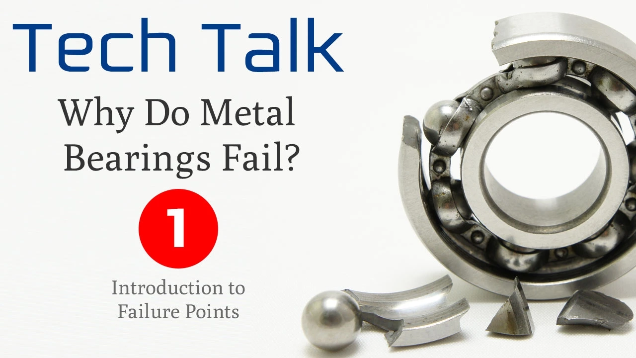
Rolling element bearings fail primarily due to four major categories: lubrication issues (accounting for over 50% of failures, including incorrect lubricant selection, inadequate maintenance, over-lubrication, and contamination); corrosion from corrosive environments; contamination from seal failures or external debris; and overloading from excessive loads, misalignment, tight fits, or improper bearing selection for oscillating applications. Each failure mode creates distinct damage patterns such as spalling, brinelling, or increased vibration that eventually leads to complete bearing breakdown.
Click to watch →

SKFstronger – Bearing damage modes and classification
32.5K
Fretting corrosion develops in loose-fit applications with micro-movements and oxygen exposure, commonly between inner rings and shafts, requiring proper surface finish and tolerance control. Vibration-induced brinelling creates nest-like indentations at running element pitch distances, more severe in ball bearings and stationary conditions, with reddish discoloration. Electric current damage creates zigzag patterns with molten characteristics, common in VFD-driven motors, requiring material analysis to distinguish from other failures. These specialized modes demonstrate how specific operating conditions and electrical phenomena create unique failure signatures requiring targeted investigation approaches.
Click to watch →

Daños y fallas en rodamientos acorde a la norma ISO 15243:2017- Alejandro Pérez
9.4K
Electrical erosion occurs when excessive voltage creates electrical arcs that melt bearing material, with melted material redeposited on raceways creating craters larger than 100 microns. This damage is caused by improper grounding systems, particularly in mining equipment where lightning strikes can induce currents through transmission systems. Electrical erosion from current leakage occurs when low-intensity currents flow through bearings, commonly caused by variable frequency drives. Solutions include colloidal silver coatings and brush rings on shafts. Plastic deformation occurs from improper mounting techniques (using hammers directly on bearings) or from contaminant-induced damage. Characteristic fan-shaped or U-shaped damage patterns on raceways indicate contaminant-induced deformation. Proper mounting tools and contamination prevention are essential to prevent these failure modes.
Click to watch →

UE Systems Complimentary Webinar - Bearing Failure Mechanisms
31.2K
Bearings fail mechanically through a progressive cycle of compression and relief. Each roller carries a stress cone through the load zone, creating approximately 21 million cycles per day at 1775 rpm. This repeated stress causes subsurface fatigue cracks forming 5-7 microns deep—transparent but detectable under magnification. These cracks generate high-frequency acoustic emissions detectable by ultrasound. Once cracks connect, spalling occurs where metal chunks break away, accelerating rapidly because larger contact areas compromise lubricant wedge integrity. The P-F curve shows gradual progression from subsurface fatigue to spalling, with final stages occurring much more quickly once initiated.
Click to watch →
BOLTR: Induction Motors EXPLAINED! | Power Factor and Failure Analysis
724.2K
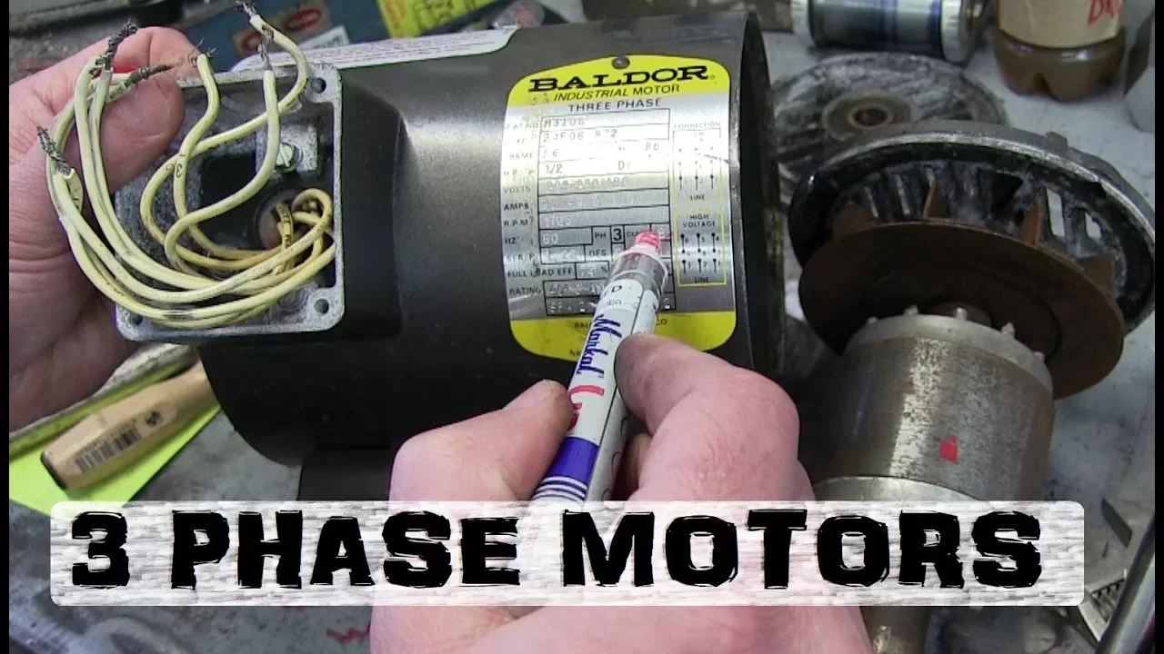
Bearing failure analysis examines inner and outer races, rolling elements, and cage components for diagnostic patterns. Visual inspection reveals pitting (stress-induced craters), spalling (flaking), scoring (particle damage), and discoloration from overheating. Conchoidal fatigue failure shows shell-like propagation patterns originating from stress concentrations like pits. False brinelling creates concentric ring patterns from stationary loads. Lack of lubrication causes rapid fatigue and pitting. Analysis requires comparing both bearing halves—the pattern indicates failure mode. Diagnostic techniques include using white bread as hydraulic fluid to extract bearings without damaging them. Understanding these failure modes helps prevent recurrence and extends motor service life through proper lubrication and maintenance practices.
Click to watch →
Deep Dive
Precision mounting and dismounting techniques, including thermal expansion assembly and the use of specialized installation tools.

Fixing The Largest Construction Equipment On The Planet | Mega Mechanics | Spark
4.9M
Some heavy machinery assemblies require thermal expansion techniques for proper fit. For pivot shaft bushes in dozer track frames, the bush is submerged in liquid nitrogen (-200°C) for 10 minutes while the frame is heated with gas torches. This creates a brief window to assemble components before they return to ambient temperature and friction locks them permanently. If timing fails, alternative methods using drifts and hammers become necessary. The technique demonstrates how precision engineering principles apply to heavy industrial maintenance.
Click to watch →
South Bend lathe MILLING ATTACHMENT #815 pt 2 tubalcain offset base
24.9K
This section demonstrates advanced machining and assembly methods. The operator sets up a criterion boring head with a boring bar to enlarge holes to precise dimensions (1.375 inches). Multiple passes are taken, monitored using dial indicators to track progress toward target sizes. The final dimension is verified by test-fitting the mating component. For assembly, thermal expansion is employed: heating the plug to approximately 600°F causes it to expand, allowing easy insertion into the receiving hole. Upon cooling, the plug contracts to create a tight press fit. This technique eliminates the need for adhesives or mechanical fasteners while ensuring secure, vibration-resistant assembly.
Click to watch →

Hydraulic Cylinder Trunnion Mount Repair - Manual Machining
60.6K
Thermal expansion is used to assemble tight-fitting components by heating the mating part to cause temporary expansion. The machinist uses a torch to heat the bushing until it expands sufficiently to fit over the trunion stub. If the thermal expansion alone is insufficient, an arbor press provides the necessary force to complete the assembly. The temperature control determines whether the component drops on by itself or requires mechanical assistance.
Click to watch →

MAKING ULTRA PRECISION TOOLROOM SPINDLES #2
101.7K
Heat treatment only changes steel's yield point and hardness, not its modulus of elasticity (stiffness). Blind mounting systems use eccentric pins and magnetic chucks with 2-degree tapers that engage securely without slipping. For precision workholding, parts should be packaged in fitted containers so service providers can easily return them in their original orientation without instructions. When mounting parts, parallel bars are positioned across two pins 180 degrees apart to establish center alignment. The mounting holes are drilled slightly off-center so parts can float and self-center in the spindle. These techniques ensure consistent positioning and prevent damage during handling.
Click to watch →

Deckel FP1 - DRO, slotting head, crane
114K
This section addresses the practical challenges of adapting tooling systems and achieving precision mounting. Key topics include: (1) Adapter design principles for transitioning between different shank sizes while maintaining alignment through machined reference surfaces; (2) Chuck modification techniques converting back-mounted configurations to front-mounted arrangements using through-hole drilling; (3) Precision mounting methodology using dial test indicators for verifiable accuracy; (4) Chuck indicating procedures involving light jaw tightening and tapping to find high spots; (5) Circular pattern drilling setup using pitch circle diameters and coordinate systems; (6) Tap hole preparation including spot drilling, counterboring, and chamfering for proper screw engagement.
Click to watch →
Deep Dive
Integrating bearings into 3D CAD modeling and performing finite element analysis (FEA) on shaft-bearing-housing assemblies.
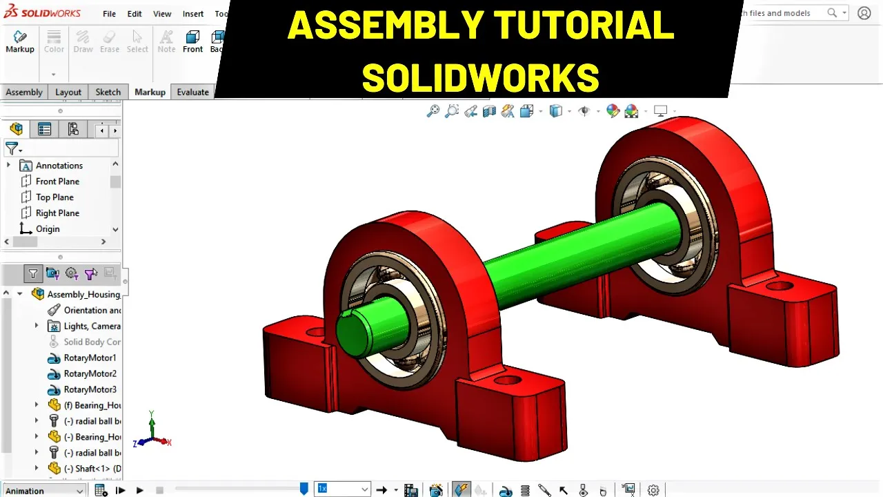
Shaft Bearing and Housing Assembly Tutorial in Solidworks
23.8K
This tutorial demonstrates how to assemble a shaft bearing and housing system in SolidWorks by importing bearing housings from the Design Library, inserting radial ball bearings with specified parameters, creating a shaft part with extruded boss and cut features, and using mate constraints (concentric and distance mates) to properly align and constrain the components for functional assembly.
Click to watch →
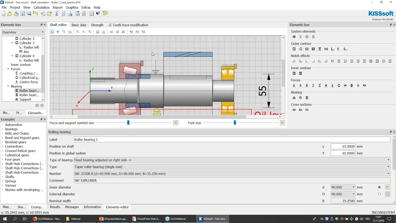
Web demo Shafts and Bearings Calculation
29.6K
KISSsoft supports complex coaxial shaft systems including planetary carriers and multi-shaft transmissions. Connecting bearings between shafts can be rolling element bearings, general supports, or sliding bearings with identical properties to regular supports. General connecting elements enable per-degree-of-freedom boundary condition definition, allowing creation of shifting transmissions by fixing rotation around specific axes. Preload in tapered roller bearings can be modeled through initial offset definition or stiffness-based spring application. Housing stiffness integration allows modeling outer ring connections with specific stiffness values or full housing stiffness matrices. The software database is extensible, allowing users to add custom bearing entries beyond manufacturer-provided data. For critical high-speed or extreme applications, manufacturers should provide actual energy AMA tree data rather than relying solely on catalog values.
Click to watch →

Week4 Lab Presentation 2026 CAE MECH4259, May 29 2026
168
This video demonstrates how to perform finite element analysis on mechanical assemblies using CATIA software, covering two key assembly types: (1) a shaft bearing assembly where a shaft is supported by two bearings with a welded connection to prevent rigid body motion, and (2) a shrink fit assembly where two rings of different materials (steel and brass) are joined through thermal expansion and contraction, creating radial interference that generates contact pressure. The instructor explains how to create assemblies, apply restraints and loads, define contact connections, and visualize stress distributions including von Mises stress and principal stresses.
Click to watch →

Best 3D Printed Bearing Design
33.8K
For Onshape users, configurable bearing designs allow easy integration into mechanical parts. The process involves extruding an axis from components, using subtract operations to create holes in base parts, adding center holes to save material, and then using configurable parameters to specify bearing dimensions. Users can control which bodies are created (inner race, outer race, or gap part) and position the bearing precisely within assemblies.
Click to watch →
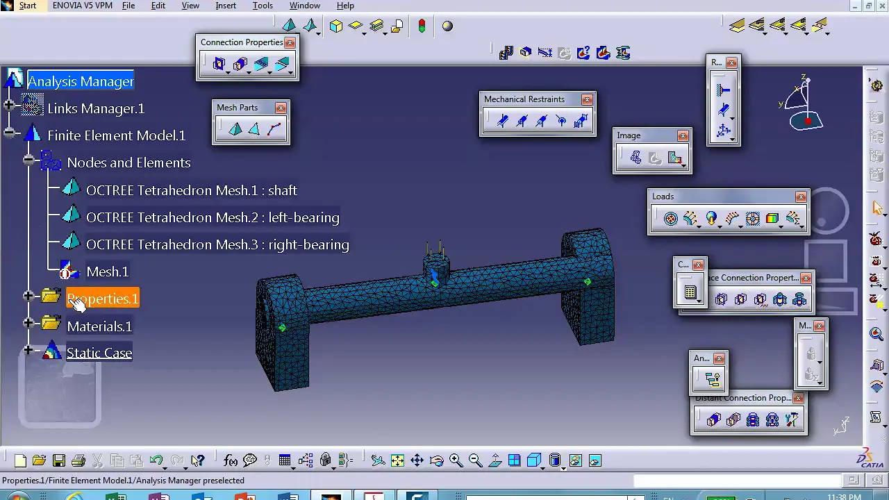
FEA, Chapter15 Shaft Bearing Assembly no planes of symmetry used, Catia v5, Nader G Zamani
1.6K
This extended segment demonstrates the complete workflow from geometric modeling to initial FEA setup. Key topics include: (1) Creating shaft geometry with appropriate dimensions (1-inch diameter, 10-inch total length); (2) Creating identical bearing components using projection techniques; (3) Applying consistent material properties (aluminum) across all assembly components; (4) Automatic mesh generation in CATIA Generative Structural Analysis; (5) Mesh refinement techniques for critical areas like shafts; (6) Visualization tools for examining finite element discretization; (7) Applying boundary conditions including clamped supports and concentrated loads; (8) Understanding that improper constraint application causes analysis failure.
Click to watch →
Bearing Basics
Shield vs Seal
Bearing Basics
0:00- 1
Identify bearing by bore size: round or hex.
- 2
Flange locates depth in through holes; non-flange is cheaper.
Tribology-First and Non-Contact System Design
While standard guides focus on selecting discrete rolling-element bearings using physical attributes like bore size, flanges, seals, and shields, a major counter-perspective in high-performance engineering advocates for a 'Tribology-First' or 'Non-Contact' approach. This viewpoint argues that traditional component-level selection is outdated and prone to failure under complex dynamic loads. Instead of choosing physical barriers like seals or shields—which introduce friction, heat, and wear limits—modern design increasingly leverages active magnetic levitation, air bearings, or fluid-film lubrication. By eliminating physical contact, these alternative technologies render traditional selection criteria (like shields and physical seals) obsolete, offering near-zero friction, virtually infinite operating life, and no lubrication maintenance. Additionally, reliability engineers argue that bearing selection should be driven by dynamic digital-twin simulations of the entire system's thermal and chemical environment, rather than relying on static catalog dimensions and standard physical configurations.
Fundamental concepts of rotational motion, friction, and the primary purpose of bearings in mechanical systems.
Understanding the difference between radial, axial (thrust), and combined loads in structural or machine design.
Basic knowledge of engineering tolerances, fits (e.g., clearance, interference), and shaft/housing dimensioning.
Awareness of environmental factors in mechanical design, such as dust, moisture, and temperature, and the general need for lubrication.
Calculating bearing fatigue life and dynamic/static load ratings using standardized formulas (such as ISO L10 life).
Advanced lubrication engineering, including selecting the right grease or oil viscosity and determining relubrication intervals based on speed and temperature.
Analyzing bearing failure modes (such as spalling, brinelling, and electrical erosion) to diagnose mechanical issues in the field.
Precision mounting and dismounting techniques, including thermal expansion assembly and the use of specialized installation tools.
Integrating bearings into 3D CAD modeling and performing finite element analysis (FEA) on shaft-bearing-housing assemblies.
5.3K views57likes3:00@AndyMarkOriginal Release: 2021-11-26
how do i choose which bearing to use [Music] so bearings are useful with handling a rotating device either a wheel or a gear or a shaft many of those items use bearings they use bushings also but today we're going to talk about bearings first of all your bearing is defined by the bore these are half inch round bore bearings this is a 3 8 bore bearing it's slightly smaller this is a hex bearing it's used to help a hex shaft rotate you can see that the the round bore bearing goes on around part of the shaft the end has a 3 8 portion so i can spin the shaft on a round board bearing this bearing has a flange located on the bottom of this setup you can see the flange here and what the flange does is it locates the bearing in a hole you can have a through hole and you push the bearing into the hole and it stops on the flange so that locates the depth of how far you're putting the bearing into the hole if you had a hole with a bottom on it you wouldn't need a flange so you would just push the bearing all the way into the hole until it bottoms out on the bottom of your hole usually non-flange bearings are cheaper than flange bearings so if you have the ability to design in the bottom of a hole you're going to save some money by having a non-flange bearing the basic structure of the bearing is seen within this open bearing here it has an outer race and an inner race those are those two rings the middle of the bearing has balls and it has a cage surrounding the balls that's what keeps the balls in place as inner race moves or if the inner race stays still the outer race moves you can see the balls move with that moving portion of the bearing rarely would i recommend using an open bearing as opposed to the shield the shielded or the seal bearing the benefit of open bearing is it's it's geometrically thinner so it saves you some space but you can really only use these in clean situations where there's not any debris you really need a seal or a shield to keep debris out of the inside of your bearing there's two distinct differences between a sealed bearing and a shield bearing a shield bearing can handle higher rpms as the bearings get bigger a sealed bearing can handle a little bit more misalignment from an axial shaft like if you have a gearbox with two or maybe even three bearings in it a seal bearing is going to handle misalignment or binding better than a shielded bearing and that's how you can choose what bearing to use [Music] you
Up Next

18:40
NEMA17 Stepper Motor Test With Dynamometer: LDO vs STEPPERONLINE
@engineerbo
95.3K views•2024-06-30

12:54
Triumph of Orthodoxy Icon: Byzantine Art & History Explained
@BenCallan
2.1K views•2024-08-06

9:49
FastAPI vs Flask vs Django: Choosing the Right Python Web Framework
@TechWithTim
302.5K views•2024-05-26

1:42
Game of Thrones Opening Credits: A Cinematic Analysis
@gameofthrones
46.3M views•2011-04-18
Related Study Plans & Knowledge Roadmaps
Structured learning paths in General & Interdisciplinary Studies
general-studies
Elevator Engineering: History, Physics & Cities
01From Hoists to Safety Brakes: The Dawn of Vertical Lift
02Hydraulic vs. Traction: The Engineering Physics of Elevators
03Modern Speed, Safety, and Algorithms
+ 2 more learning modules
12h5 modules
Explore Roadmap
general-studies
Rubber: Material Science, History & Geopolitics
01Origins of Natural Rubber & Mesoamerican History
02The Chemistry of Natural Rubber & Vulcanization
03The Geopolitics of the Rubber Boom & Colonization
+ 2 more learning modules
12h5 modules
Explore Roadmap
general-studies
Containerization: Evolution, Logistics & Trade
01Ancient Trade & Bulk Cargo: Amphorae to Barrels
02The Industrial Revolution & Cardboard Packaging
03The Containerization Revolution: Malcom McLean
+ 2 more learning modules
12h5 modules
Explore Roadmap
general-studies
Textile Tech: Evolution, Labor & Global Impact
01Pre-Industrial Textiles: Handloom & Cottage Industry
02Mechanization: The Spinning Jenny to the Power Loom
03The Factory System & Global Labor Transformation
+ 2 more learning modules
10h5 modules
Explore Roadmap