




















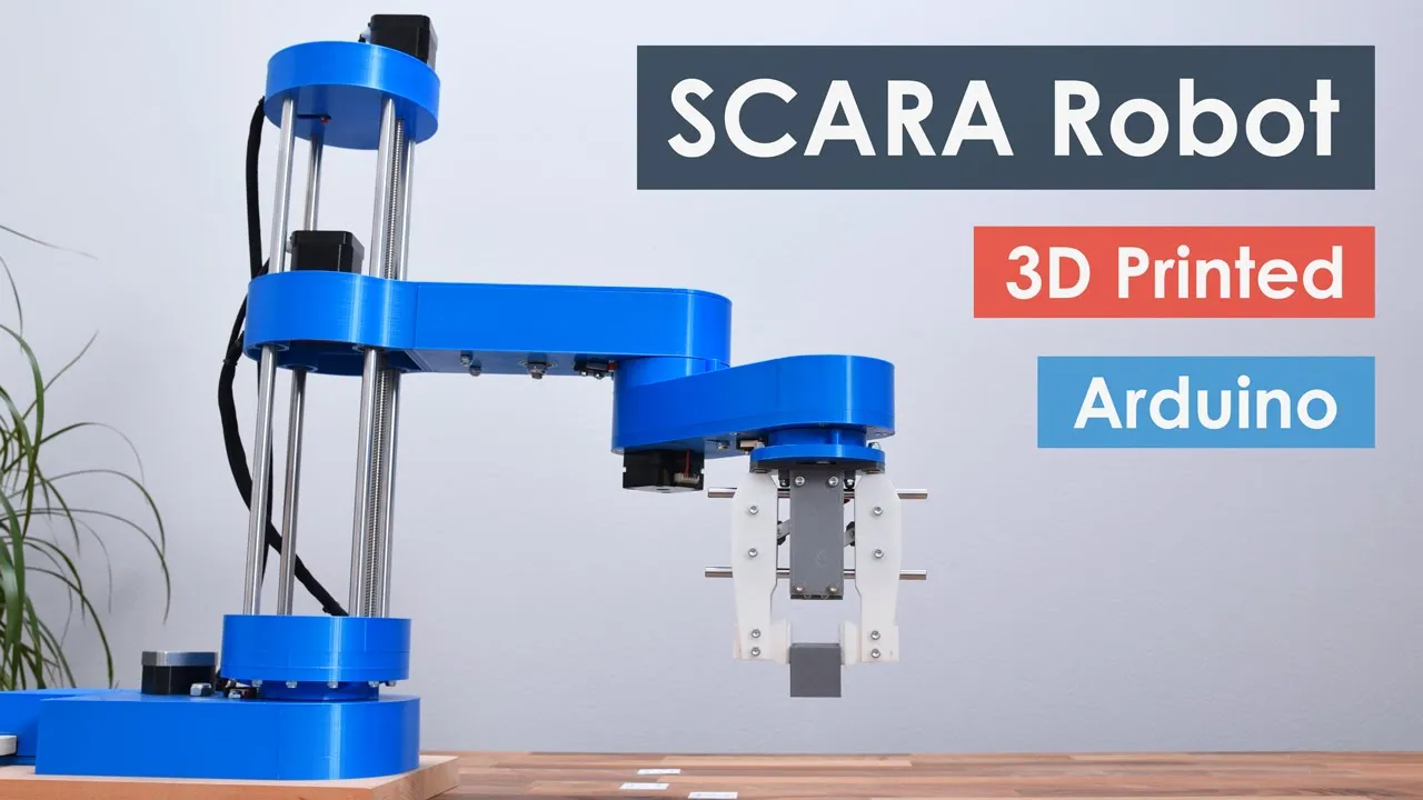

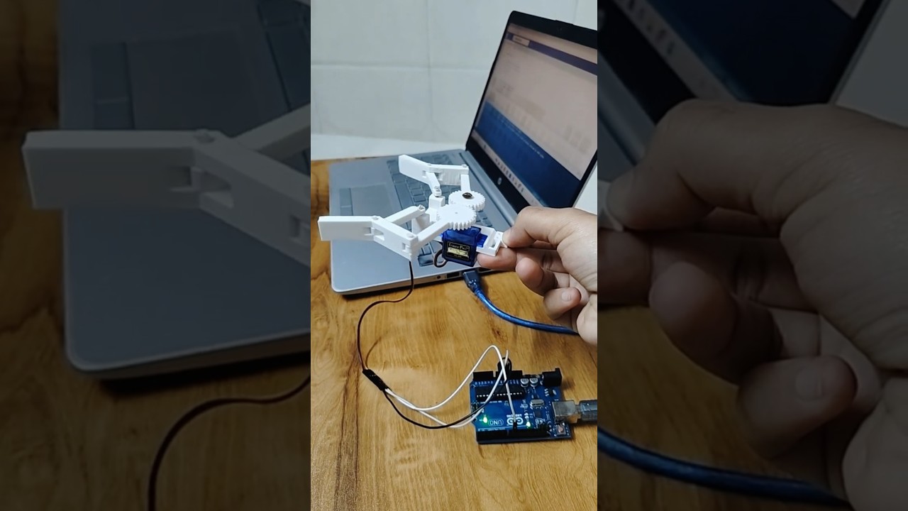

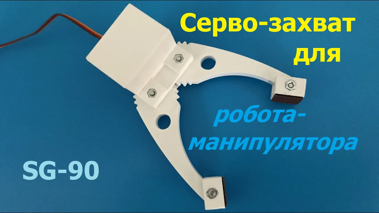
This tutorial demonstrates how to design a robotic gripper in Autodesk Fusion 360 by creating individual components (gripper flange, connecting rods, base, and gears) using sketch-based modeling techniques, then assembling them into a functional mechanism using joints, motion links, and rigid groups to enable coordinated movement of the gripper fingers.
Fusion 360 Robotic Gripper Tutorial: CAD Design & Assembly
Added:Basic Fusion 360 UI navigation and 2D sketching concepts, including geometric constraints and dimensioning.
Fundamental 3D modeling operations such as extruding, revolving, and differentiating between bodies and components.
Elementary mechanical principles of gears and linkages, such as gear pitch, mesh, and simple mechanical advantage.
The concept of Degrees of Freedom (DoF) in mechanical assemblies and how components constrain each other's movement.
Advanced Motion Studies and Kinematic Analysis to simulate and animate the gripper's exact physical trajectory and speed.
Finite Element Analysis (FEA) and stress simulation in Fusion 360 to evaluate the structural integrity and load capacity of the gripper fingers.
Design for Manufacturing (DFM) principles, specifically optimizing the parts for 3D printing (FDM) with proper tolerance and clearance allocation.
Actuation and Mechatronics integration, including selecting appropriate servo motors and microcontrollers (e.g., Arduino) to physically control the gripper.
144.5K views2.4Klikes38:41Original Release: 2022-03-24
hey guys and welcome back to another video of the spark plug so in this video tutorial i will be showing you how to make this robotic gripper in fusion 360.
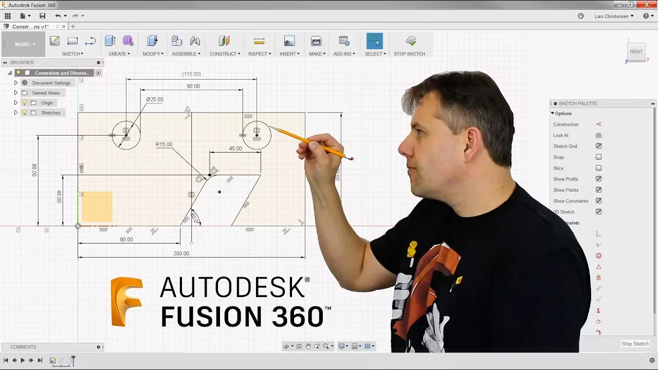
so uh uh i i'm thinking to make this video in two part but i'm not sure right now uh it will depend upon how long the first video will take so as you guys can see this is via it has got two plans here and some connecting rod and two gears which is operated by a servo motor and this they all are mounted on this white frame so basically uh this is all 3d printable you guys can easily 3d printed as it is so the motor part is i am not quite sure i have on those of you who are my previous viewers uh my previous video was on this stepper motor so i have used the exact same stupid motor here just for demonstration by the way i am taking responsibility till this gear it's up to you which motor you are using to make this creeper in motion so let's get started without wasting any time we will start by making one foot here and then we will make a mirror copy of this and remember that uh there are two options either to make it thick but i have chosen not to make only a one and then [Music] make it double like this so two there are if i just hide this there are two uh here two separate body then there are two separate bodies here so let's get started we will start by making this flange here so it's just doing your space go to create a sketch and on the top plane we will start by making some sketches so for starting as you guys can see it's slotted here we will start by making a slot so let's go to slot center to center slot and make us oh one more thing every dimension that we will be using is uh this so make sure the dimension is mm so just go to create go to slot go to center point slot and make a slot like this press d for dimension and give this dimension as 22 the dia right click on it and choose diameter the diameter is going to be 10 mm yeah now press c4 circle and make a circle of dia 3 mm here a hole now once done make a line and from somewhere here make a rectangle like this ah currently just don't follow you don't have to follow any dimension just make sure that uh we don't have tangent relation of vertical relationship here so let's go for perpendicular relationship make sure that both of these line are perpendicular to one another plus d again and from this point to this line make this angle as 157.65 now once done right click and align and this eyeline dimension is going to be 34 yeah so the next dimension is from this point to this point the vertical one so the horizontal dimension is 1.95 like this now if i just make a tangent relationship so you don't have to give any other dimension for now so you can see that my sketch is fully constrained now what i'm going to do let me show you what i'm going to make this cuts and this cut so for that i have not assumed any dimension let's see what i'm going to do here i just going to make a cut here and about some distance like here i am going to make another cut like here to here and make these two line parallel to each other yeah so you guys can just alter the uh size of the tooth here as you wish you will understand just give me a some just give me some time here so press c again and make a 3mm dia half circle here also and finish the sketch now i am going to extrude it select this one and this one just leave the outer part and extrude it upwards up to a distance of 3 mm and it would be obviously be our new component press shift and and to enables the color okay if you are thinking that this is not suitable so anytime you can just go to create a sketch and just alter the shape of it like this and you may finish this okay so a reason that i didn't made any dimension is to allow a small degree of freedom to change the dimension at any particular time so this is the exact portion that we will be making the teeth here so as you guys can see these are not considered when the t's are considered okay so we have completed making our uh gripper so now the last thing is to make this connecting rods so for that of course just hide this for now click on uh sketch and press c4 circle make two circle like this and make two circle like this press n join these two circles press d and the outer is going to be seven and the inner is going to be three repeat the same for here seven and three and this is going to be 31 yeah so and press line make a line like this from this press d again and from this point to this point make this 1.5 then mirror it mirror this line up to center point and finish the sketch now extrude this up to a distance of 3mm and this again will be our new component so once done you can just give the fill it or let me just to make the video shorter i'm not going to be now i'm not going to make any fillets so you guys can see i have created some fillets here and here so these are all assumed you guys can take care of that so we have our first part and the second part now for the third part i am going to make this base here so for that let's create a sketch let me just hide this and create a sketch on top plane we will start by making a top plane stitch press l for line and from origin make a vertical line up to a distance of 62.
so let's make a vertical line of 62 and for now just make it in construction mode so i have a construction here now from this point draw a figure something like this now once done press dimension d for dimension and start giving dimension to them just like i did i am doing here okay so from this point to this point this is going to be 20.5 the length is going to be 30 points 30.3 this one a line dimension is going to be 18.85 and this one okay i don't know why let me just delete this yeah so our sketch is finally fully constrained we don't need any dimension now i'm going to make three holes around different places so all of uh 3mm so first is going to be here second would be somewhere here and third one would be somewhere here all 3 mm diabole now from this point to this point make it 4 from this point to this point make it 2.75 now as per this is concerned from this point to this point this dimension is going to be 10.3 mm from this point to this point this dimension is going to be 7 mm you guys can pause the video at any time to capture the dimension better so from center line this is going to be six and from bottom this dimension is going to be four now once done i'm just assembling it like this so you guys can snap that out and make once turn go to mirror command select all these lines select the middle unselect the center line and select the center line as the mirror one and finish the sketch now we have a mirrored view press c for circle and right on [Music] this line make a circle of dia 17 mm press d again and from this point to this point make this dimension as 13 ml now in order to ah make it fully constant i am going to make a vertical line from here to here and make this line coincident to this one so we have a fully constrained sketch and a circle here the diastolic team now you may finish the sketch click on extrude and extrude it again up to 3 mm this is going to be our new component and press ok now as you guys can see in my if i just hide this and this you can see this is a there's a cut here the reason for this curse is just to minimize the load uh minimize the weight of this particular part because we will working on these holes not the part that is solid so what i have done here you guys can create any just bus but to save the time i have just drawn some random ellipse like this in order to complete the sketch so this is just to make some designs you can can play it with as you want so this is how this will look like now for the next part of course we will be using these two square gears so for that go to utility go to adsense and scripts and ads in and the bottom you will find the uh is per gear for c plus plus and python so go for the python this is the logo for python so this is the scripts for asperger so just double click on it it will run after here toolbar so just note that the dimension the standard would be the meter part and the pressure angle would be 20 degree the module i am going to use 1.125 the number of teeth is going to be 24 let the backlash be 0 as per the root fillet radius make it 0.1 to thickness is going to be 3 mm and the whole diameter is going to be 3mm also so we have a 3mm thickness here the hole at the center of the gear would be of 3mm dyna number of t this is the module this is the pressure angle those who are if you are not aware of this you can just google it out and check that out what this particular terms mean so once you are done just press ok and within a few seconds you will have your gear make so this is a 3mm dial hole at the center and this one now we will start by assembling our design so those who are aware of the design the first part of making an assembly in fusion 360 is to ground the mother component so in this case our mother component is going to be the space so what i'm going to do is you can just rename the component for better understanding in time but i'm not doing that right now so just completely grounded the first part just ground it so i don't i can't move it now i can move this this and this but not this one because it's grounded right so i will start by assembling these two parts as you guys can see these are assembled on top of this space so we have a gear here and a tooth here so we will start by assembling the gear bust so go to solid go to assemble go to joint and select the bottom part of your gear and this hole and just go to motion select revolute and your question is completed now right click on it and click copy on the mother face click on paste new remember to click on paste new not on the paste because space new will unlink the new gear from the previous one so just like so you guys can see it's rotating here yeah so do the same for the second gear also this time the hole would be this point and this is also rotating now if i just go to top view just may place the gear so that it don't intersect with each other you can just place it anywhere but slowly and carefully place it exactly at the center of the orange gear so this is how i don't think any conclusion once satisfied just capture the position so that if i just make any changes i just revert the position and it will just go back to their original position right now the second is going to be this portion so for that i'm going to what i'm going to do is go to joint select the bottom face and this face here this again is a rotating motion okay yeah now for the tooth i am going to click on joint select the top face and the bottom face and this is also going to be our rotating motion now we have a rotating motion here as you guys can see here okay now the next thing is to make this these two [Music] what you say what you call it i don't know you can just call it anything so ah first we will start by making from this one so you can capture the position or revert back to his original position yeah so yeah here it is we are working on we will start by making a slot center to center to make a slot like this press d and this dimension is going to be 31 and the dia is going to be 8 so the radius is 4 that's it and the hole is already here you just made me to make a 3m diaphole here so make it three and press okay and once turn just extrude it downwards and the motion would be joined and the distance would be negative three because we are storing it downwards it will automatically get joined to this one you guys can see now it's joined here just revert back the position and do the same for the blue gear also uh just same step [Music] from this point to this point and the dial would be it press t again and make this as 31 press c and make a circle of 3 mm here and finish the sketch extrude select this profile go downwards minus three and the operation would be join and press ok now [Music] yeah once done go to join and make this hole join with the bottom hole and the operation will be joined okay so if i just go to top view now if i just move this this will move like this only okay so uh we will just limit the motion as you guys can see in my design it is not moving beyond a certain point so for now just leave it like that only distribute the position so leave it like that only okay yeah so the next thing is to make the mirror of these two things so for that what i'm going to do is i'm going to to construct construct a mid plane and i'm going to construct a mid plane on these two points between those two points already you can just make this plane as mirror plane also so i'm going to go to create go to mirror the type would be components select this one and this one and mirror it like this okay now again we need to provide the same dimension same joint that we have did earlier so click on these two okay and repeat the same step again and again uh we will be using tons and tons of revenue joint for this and for the last portion just bottom part of this and the top part of this and press ok now this is this is how this will move and this is how this will move now distribute back the position of the restricted point now what i'm going to do is just go to top point as you guys can see this is the angle if i just double click on it this is the angle that on which our uh the hole was making right so just place it at approximately 90 degree yeah i think 68 degrees is fine or let's make it 67 degrees yeah 67 degrees i'm trying to make this 90 degree and remember to do the same for here also so let's make it zero yeah now it's 90 degree and to check that you can just anytime [Music] yeah this is how this will look like okay now just capture the position because we have fixed or the initial position of the tooth closure just don't just forget about this part we will deal with in the later part of the design and remember not to have any collision as you guys can see there is absolutely no collision anywhere so but they are still working independently independently so what i'm going to do is i'm going to create a motion link go to assemble and go to motion link and the first joint is going to be this joint and the second joint is going to be this side now what it tells us that how much the revolution one will rotate according to the revolution two so what i am going to fish in 660 10 is that if we rotate revolution 2 by 360 degrees the rotation 1 should also be rotating at 360 degrees but the direction is supposed to be get reversed because uh both of the border gear will be working on different directions right so just direct it and press ok now if i just move it you guys can see that it is actually moving so the air both of the two gears has 24 gears so the gear ratio is one is to one so we don't have to deal with the angle so 360 degree of blue will be equal to 360 degree angle of orange one but is still you guys can see that it still they are colliding so just remember the position to break it back to the original position so what i'm going to do is this blue is currently at 0 degrees i am going to tell fusion 360 that let's just open it for example let's say uh yeah this seems fine or 60 degree or 60 degree angle i'm just assuming the maximum opening of the tool so let's say 60 degree is fine right so let's just skip again now i'm going to join select this join this is revenue 2 so right click on it and click on edit join limits so click on maximum and minimum so minimum is 0 degree the maximum is that we have calculated there is 60 degrees and you can just animate it so this is the maximum minimum limit that this particular gear will go so if i just press ok now what i will fusion 360 will restrict the motion beyond 0 degrees and 60 degrees so it will just restrict the motion between 0 and 60 degrees so we don't have absolutely no pollution if you think that this is a particular collision here so you guys can just increase the minimum from 0 to i say 2 degrees or 3 degrees okay let's give you example again so if i thinking that this is getting too close to each other right click on it i am going to make it 2 degrees like this ok something is not wrong something is definitely wrong here i don't know what actually happened okay i think this might be some glitch but uh so this is how the things make work uh you can just check that gear is not colliding with each other so that's good now the basic is just completed now we just have to double everything out you guys can see that we have doubled everything so for that let's say this point so i'm going to click on it copy and click ctrl v for paste and this the thickness is 3mm so just make it downwards by 3mm and press ok so again i'm not taking any radius you can just give the radius on your own so and remember i have click uh using the paste as paste option because any changes that we will make to this part will automatically be directed to the second part also now again go to rigid group go to rigid because uh this particular is still movable right so we need to make it rigid with the master position so just make up rigid so i can not move it now now as for the bottom part you guys can see we have used use this connecting chords only so this is the connecting dot so plus copy and ctrl v drag it ctrl v drag it we need one two how much let me just so two for the top four at the bottom so we need two mores so just control v again and ctrl b again we have a four connecting rod with us here now just move backwards and start making the joints so we'll start by from this point to this point this is the revolute and where was it yeah now i forgot one thing i need to double this two portions also so for that that just click on this and this and click on copy right click and click on paste drag it upwards up to a distance of minus 3 and press ok now again make a rigid between these two right click drag upwards make a rigid between these two also so you guys can move it like this just revert back the position now click on join command select this one and this one make it join like this so this is how this will look like and repeat the same step for this portion also so select this one press ok drag it upwards repeat joint select the bottom face of this circle and the top face of this circle and press ok like this revert back the position now we for the top portion we have used gears but for the bottom part we will not be using gears so we will just be making these two connecting rod to do our job right click drag upwards select the bottom face of this one and this one and press ok now for the last track upwards right click that upwards and this one and press ok right click drag upwards select this and this and press ok now we have our tooth working with all the joints necessary now what i am going to do is uh we will be creating some punches for the center portion remember right so for that i am going to create go to create a sketch and on top of any position i am going to create a line of length 14 and make a eye shape structure like this and give the dimension accordingly so this is going to be 1 this is going to be 1 this is going to be 2.5 make this vertical this is again going to be 2.5 and distance between these two is going to be 1.5 and this dimension is of course 14 so we have one sketchfully constrained let me just try fixing one point so we have a fully constrained sketch with this 14mm long and let me just check the dimension once again finish the sketch go to revolve select this portion the axis would be this and uh it would be new component so this is going to be our punch so click on join and go to motion this is going to be our rigid joint select this one and select this space it will automatically be decembered onto this point now again as i told you ctrl c and control v one i need one two three four five six seven so this is two this is three so let me just skip this part to make the video shorter we'll get back to you once we are done yeah so i have done with all the joints let me just hide the joints and sketches and constructions yeah so this is how this will look like now again i am telling you uh you guys can just deal with the radius that will auto definitely be give you a more beautiful and realistic view now for this care and this plan is considered i have just used the same hinge that i have used here with a 12 mm dimension and this hinge absolutely it's quite easy it's just an l shape extrusion to mount it somewhere according to your need so i will just at the last will tell you about this care also so again go to utilities go to add send and go for the python type and this time the module will be 1.1 the number of teeth will be 24 divided by 2 that's 12 gear thickness would be 6 this time the whole diameter will be altered according to you so let's make it for three right now okay and now once done let me just check again down the dimension root and press ok so yeah so this is our here here now go to solid go to a sketch and on top of this sketch make a circle of dia17 finish the sketch just and extrude the these two profiles up to a distance of 5 mm like this now once done go to joint select this space and this face and just flip it like this yeah this is okay now the motion would be of revolute and go to top view and position and just make it in the center and press ok so you guys can see that it is can be moved like this so just drag it till it's get into the center and capture the position now bring back the joints now what i'm going to do will be linking these two joints remember the gear ratio here is 24 divided by 12 so gear ratio is one one is to two that means every 360 rotation that this we take the blue would take 180 degree rotation so go to a symbol go to motion length select this joint and this joint so this is our revenue two so every 360 degree uh every 360 degree and the revolute for every 360 the revenue 2 would make a half of it so 180 degree and just okay as you guys can see that action is still so we just reverse it and press ok now if i just drag it like this you guys can see it's moving like that so no need to check that it's making contact or not but it will make contact in actual conditions right so as but but we have earlier made a limit to this joint so it will not allow fusion will not allow it to move beyond a certain point okay now you guys can increase or decrease if you want the thickness of this so let's decrease it and make it equal to approximate approximately yeah this work yeah so now the last part is to this is the place where your stepper motor will come right exactly like this now as for the teeth you can just remove unnecessary treat any time for example let me just rewrite the position uh as you guys can see the only these certain number of teeth are in working so these are the teeth that you can remove or you may not remove it's all up to you i have removed it into the in previous version so i just make and sketch a circle and just extrude cut all the unnecessary teeth now in the ideal position what i'm going to do is i'm going to extrude this let's revert the position or let me just make it to the closest they can go and capture it and extrude it up to a certain point now once done let me just hide this component and repeat the same step for this one just extrude it like this okay now just bring back the component so we have extruded the bottom component and now on top view this is our origin right so this is the center line that we have here with us yeah so i am going to make a cut a rectangular cut to make them equal with each other so let's make this rectangle symmetric with origin line yeah once done once you are done you can just extrude cut it so for this part to [Music] okay i think i have done something wrong let me just delete this sketch [Music] and release all these to extrusion as well so the best way is to calculate the distance between these two and just make a extrusion for that so let's just calculate the distance from this point to this point is 0.6 aprox so we need to extrude it up to a distance of 0.3 only and do the same for here also 0.3 yeah so this is done so this can also be removed by you just by extruding it and making an extrude cut and as per the tip is concerned i think you guys can manage that out i have just made and what do you call that zigzag line and you just extrude it into the into the surface and just extra split body you can just use that to split that particular body and give the radius make this um flange here and and just to show i have just assembled this stripper motor from my previous video i will just put a link on this stepper motor how to make this typical motor in fusion 360 in the description below so hope you guys will enjoy so uh please reach do reach me uh i have my email id in the description below in case you are any query i am always there to help you guys out so hope you guys will enjoy the video don't forget to share and subscribe thank you and have a nice day
Up Next

189:07
OpenCV Python Tutorial: Computer Vision Projects for Beginners
@murtazasworkshop
3.6M views•2020-03-25

12:54
Triumph of Orthodoxy Icon: Byzantine Art & History Explained
@BenCallan
2.1K views•2024-08-06

9:49
FastAPI vs Flask vs Django: Choosing the Right Python Web Framework
@TechWithTim
302.5K views•2024-05-26

1:42
Game of Thrones Opening Credits: A Cinematic Analysis
@gameofthrones
46.3M views•2011-04-18
Related Study Plans & Knowledge Roadmaps
Structured learning paths in General & Interdisciplinary Studies
general-studies
Elevator Engineering: History, Physics & Cities
01From Hoists to Safety Brakes: The Dawn of Vertical Lift
02Hydraulic vs. Traction: The Engineering Physics of Elevators
03Modern Speed, Safety, and Algorithms
+ 2 more learning modules
12h5 modules
Explore Roadmap
general-studies
Rubber: Material Science, History & Geopolitics
01Origins of Natural Rubber & Mesoamerican History
02The Chemistry of Natural Rubber & Vulcanization
03The Geopolitics of the Rubber Boom & Colonization
+ 2 more learning modules
12h5 modules
Explore Roadmap
general-studies
Containerization: Evolution, Logistics & Trade
01Ancient Trade & Bulk Cargo: Amphorae to Barrels
02The Industrial Revolution & Cardboard Packaging
03The Containerization Revolution: Malcom McLean
+ 2 more learning modules
12h5 modules
Explore Roadmap
general-studies
Textile Tech: Evolution, Labor & Global Impact
01Pre-Industrial Textiles: Handloom & Cottage Industry
02Mechanization: The Spinning Jenny to the Power Loom
03The Factory System & Global Labor Transformation
+ 2 more learning modules
10h5 modules
Explore Roadmap