![Guide to significantly increase efficacy of maintenance in biotech plants [Flex-Pure™ EPDM]](https://i.ytimg.com/vi/ZYjNMnCET20/sddefault.jpg?sqp=-oaymwEmCIAFEOAD8quKqQMa8AEB-AH-DoACuAiKAgwIABABGGUgZShlMA8=&rs=AOn4CLBnK5OR60UmwMvAe2iDWfXcQhcsYA)












![[실습 #12] 아이폰 방수 방진과 연관된 기계 부품! ANSYS 구조해석 따라하기 예제 / Sealing 비선형 컨택 해석 / 유한요소해석, FEM, 비선형, O-ring](https://i.ytimg.com/vi_webp/HrWi7y0FAl0/maxresdefault.webp)
![[실습 #12-2] 🚿Sealing 방수 해석 기초 실습! ANSYS 구조해석 따라하기 예제 / 비선형 컨택 해석 / 유한요소해석, FEM, Nonlinear, O-ring](https://i.ytimg.com/vi_webp/7-phTNWWSK4/maxresdefault.webp)



O-rings are simple yet effective sealing components that work through a self-energizing mechanism where increasing fluid pressure compresses the ring tighter into its groove, enhancing the seal; proper design requires selecting appropriate materials based on working fluid and temperature, choosing between radial (flange or piston seals), face, or boss seal configurations, and ensuring correct installation parameters including 18-25% squeeze, less than 5% stretch, and keeping gland fill below 85%, while backup rings made of plastic-like materials can significantly increase pressure resistance from 2,000 to 5,000+ psi.
O-Ring Seal Design: Selection, Groove, and Installation Guide
Added:Fundamental properties of elastomers, including hardness (durometer), elasticity, and compression set.
Basic principles of fluid mechanics, specifically how static and dynamic pressure affect fluid containment.
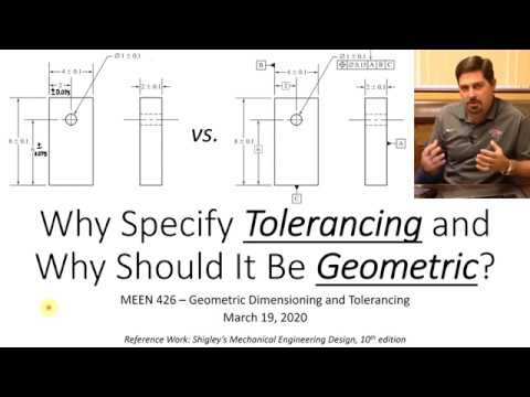
Engineering drawings and tolerancing (GD&T) basics, essential for understanding precise groove dimensions and clearances.
Chemical compatibility concepts to understand how different fluids and gases interact with elastomeric materials.
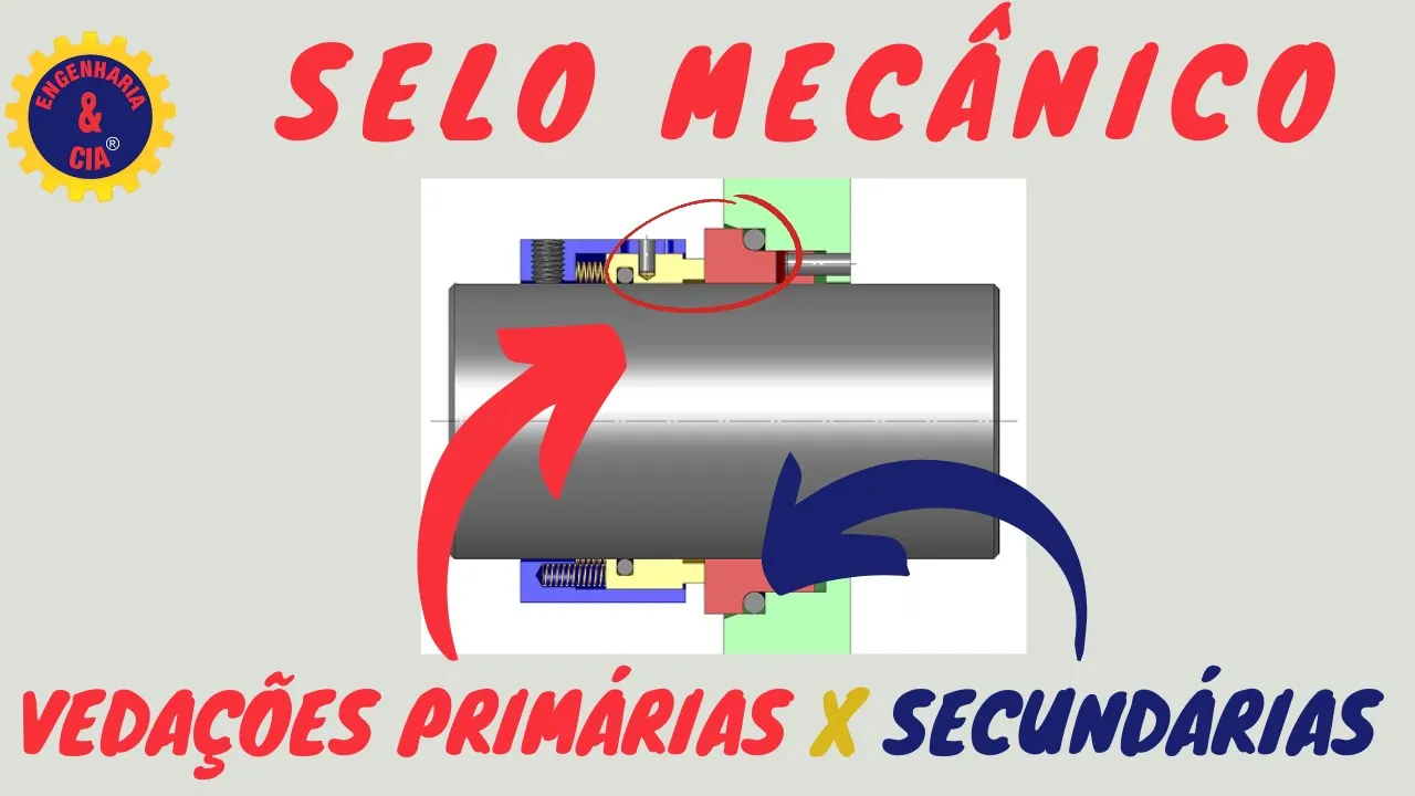
Dynamic sealing design, exploring the complexities of rotary and reciprocating seals, friction, and heat dissipation.
Failure analysis of O-ring seals, studying common failure modes such as extrusion, spiral failure, and explosive decompression.
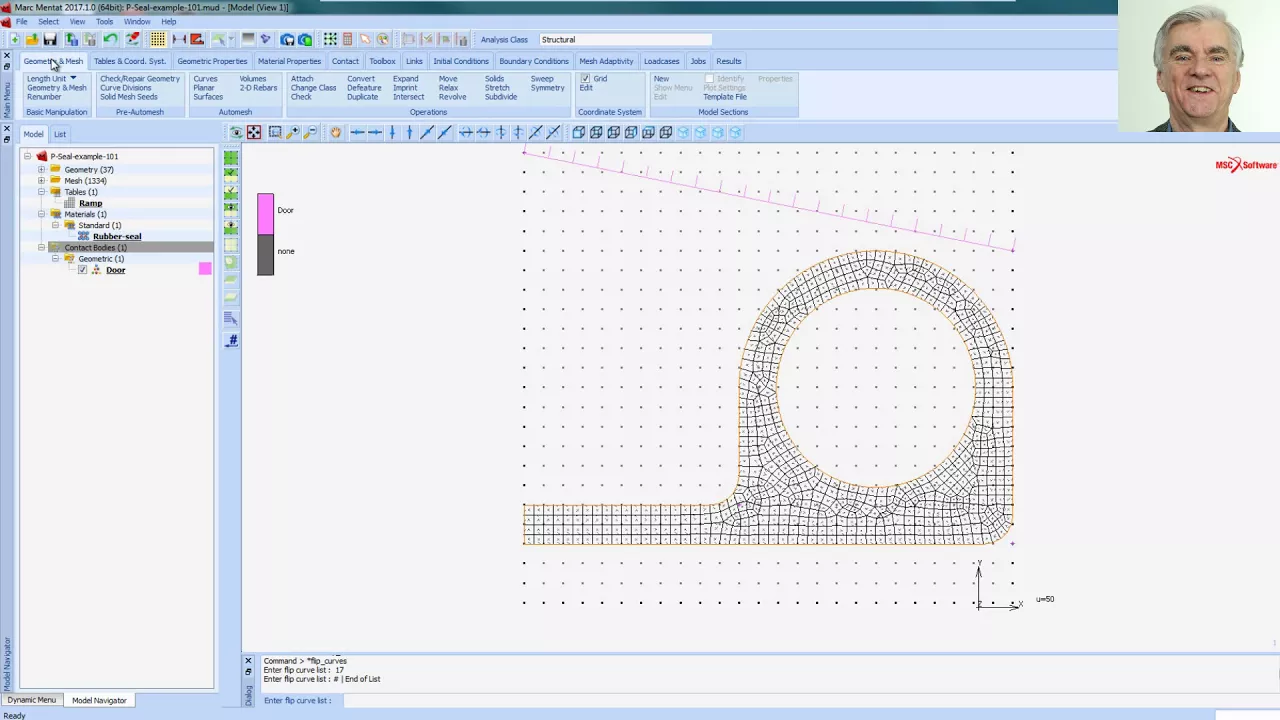
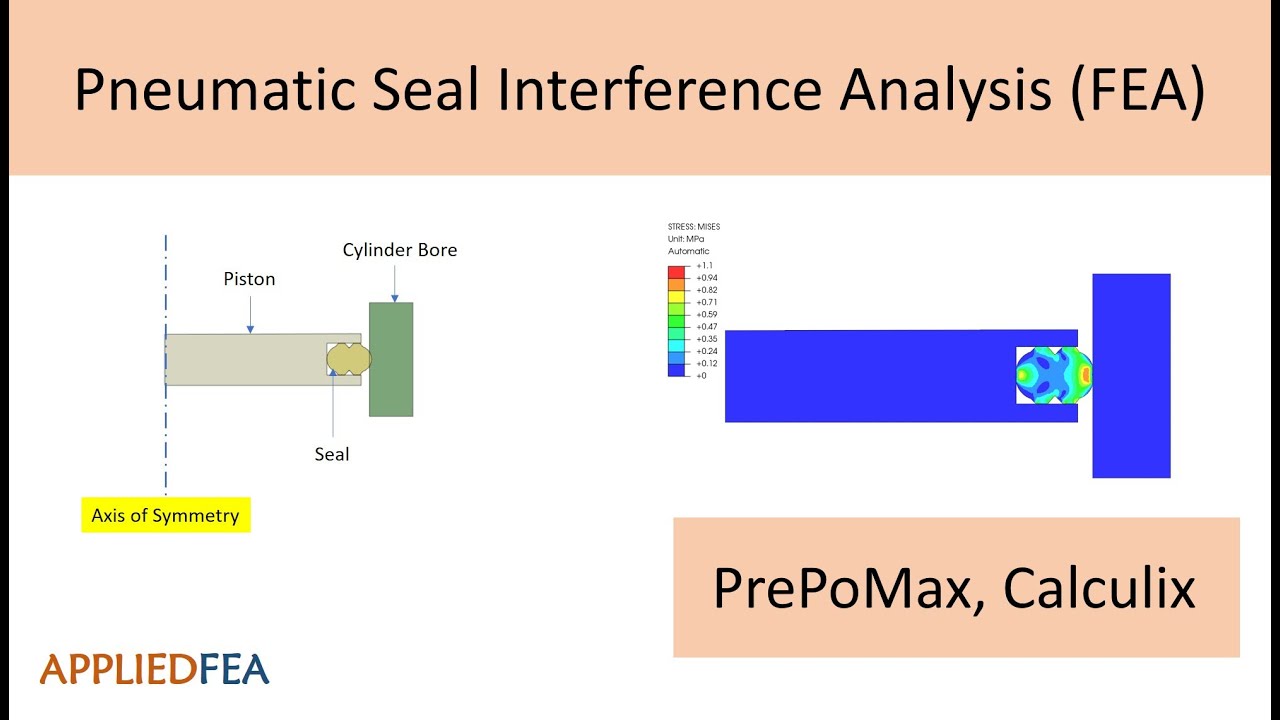
Finite Element Analysis (FEA) of elastomeric components to simulate seal deformation and contact pressure distribution under load.
High-performance and extreme-environment sealing alternatives, such as spring-energized PTFE seals and metal O-rings.
1.6M views21.6Klikes7:29Original Release: 2019-03-24
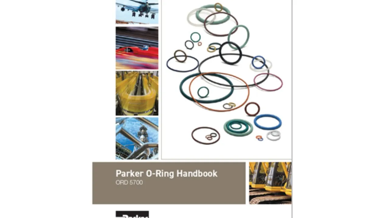
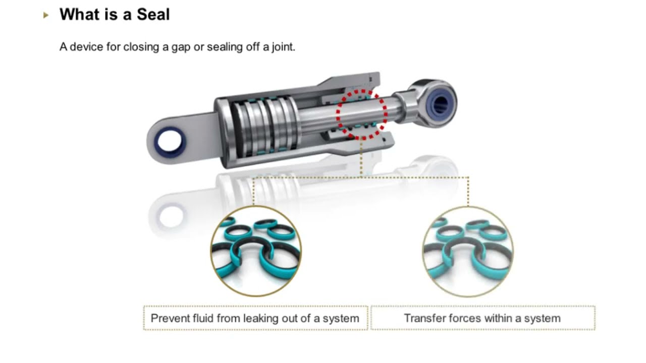
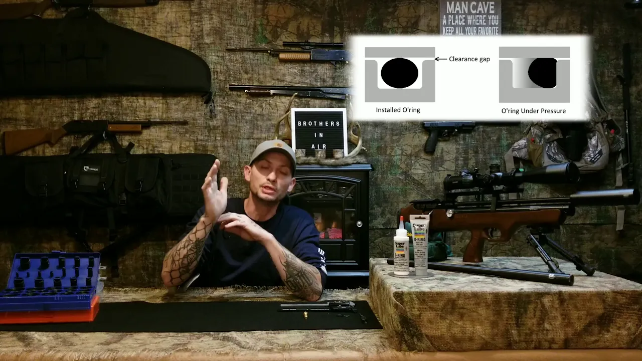
Oh rings of the epitome of elegant engineering the ring itself costs only a few cents and the groove it goes in is simple and easy to manufacture but despite the simplicity the resulting seal is able to reliably hold many thousands of psi of pressure o rings are definitely a machine design component you'll want to be familiar with and in this video we're gonna tell you all about how to design seals with them an o-ring forms a seal when it's squeezed between two adjacent surfaces as the ring is squeezed a contact stress between the o-ring and the surfaces emerge the fluid pressure is lower than the contact stress then the seal prevents the fluid from escaping in general as the fluid pressure increases the o-ring is compressed even tighter into the groove further increasing the contact pressure and hence helping the o-ring seal even better this positive feedback loop of increasing pressure needing to increase sealing is called self energizing seals can generally be classified as either static or dynamic this hydraulic cylinder has examples of both the seals between the cylinder and the end cap declaimed in the end captain the piston and the rod are static seals since these components don't move relative to one another after the cylinder is assembled the seals between the piston and the cylinder and the rod in the end cap are dynamic seals since these components slide when the cylinder is actuated the most common type of seal is a radial seal which can be designed in one of two ways if the groove is on the ID of the housing this is called a froth seal if the groove is on the OD of the shaft then this is a piston seal if you have a choice between a rod and a piston seal it's better to go with a piston seal because the groups are much easier to machine and inspect the biggest weakness of radial or ring seals is that the clearance between the components creates a path for the o-ring to extrude due the pressure acting on it components called backup rings can help alleviate this backup rings are designed to spring out of the gland and block the extrusion gap where an o-ring alone could withstand perhaps only 2,000 psi a backup ring can help it hold 5,000 or more backup rings are very cheap and effective they're made of a plastic like peak or teflon and they usually have a scarf cut to help you install them in the gland technically speaking if you only had pressure in one direction you could get by using only one backup ring however it's very easy to put the ring on the wrong side so is it designed for assembly precaution if designing with backup rings you should always design for two another configuration is a face seal what you might use when trying to seal an enclosure these are really a type of gasket and they require a clamping force usually provided by fasteners to compress the o-ring may seals are actually really tricky to get right because squeezing the o-ring requires a great deal of pressure the first lift design is far too thin and in the middle there's virtually no squeeze on the overhang and hence no sealing we can fix this design by adding a lip around the perimeter a third type of design is a boss seal you pretty much only see them on hydraulic fittings but they have a lot of advantages for other applications in this configuration the overing sits in a triangular space that is usually made with a special form tool boss seals are really easy to manufacture since there aren't any undercuts and if the gland gets damaged they can be reworked just by machining the profile slightly deeper regardless of the gland design you select you'll likely need to choose an off-the-shelf o-ring from a catalog o rings are available in standardized sizes the most common standard is a s 568 in each size is assigned a dash number o rings conforming to these sizes are available in many different materials the primary considerations for selecting material is the working fluid and a temperature Design tables like this one and the Parker o ring handbook are the easiest way to select the material that's appropriate for your application the same material is often available in a range of different harnesses the harness is typically expressed as the durometer hardness 70 is a fairly typical hardness and is good for most uses 55 durometer is much softer and is a good choice for pressures below maybe a thousand psi because of this easier to install and less sensitive to surface finish 90 durometer is extremely hard and consequently is more resistant to extrusion for higher pressure succeeding may be 6,000 psi you'll definitely want to consider using 90 do however the better high-pressure performance comes at a price ninety durometer rings can be really difficult to install particularly in small sizes a good tip is to drop them in hot water for a few minutes to let them soften they will be a bit easier to install another important installation tip is to apply high-quality oring grease before assembling the parts in addition to lubricating the rubber and helping it slide easier most overran grease is designed to cause the o-ring to swell slightly helping increase the squeeze after installation when you assemble the components you need to squeeze the o-ring quite a bit to create a seal it helps to have a shallow entry angle of about 15 degrees this surface should be totally smooth and free of burrs so that the ring is an inverted ly cut surface finish on the components is extremely important as a general rule decided a gland and a bore or rod should have a 32 rms service finish for static seals the wall of a gland can be slightly rougher at 64 this is where the piston seal really shines since it's typically more difficult to verify the dimensions and finish on a rod seal gland in a dynamic application ovens can work but there are much better options to consider this is called a tea seal and they are specifically designed for dynamic applications they're packaged with two pack of frames as a unit and their primary advantage is that they have a wide flat bottom to keep them from rolling around in the groove they don't cost much more than Oh rings and an hour experience are very reliable in dynamic applications up to this point we haven't mentioned where the dimensions for the components come from there are three seal parameters that will define the dimensions squeeze stretch and % gland fill squeezes how much you radially compress the overing when it's installed in the gland in general 18 to 25 percent squeeze is appropriate for most static seals but as high as thirty percent is sometimes used particularly for cold service applications stretch corresponds to how much the o-ring is tangentially stretched after it's installed at the group it doesn't directly have to do with how much you stretch the o-ring during installation though with small sizes of rings the installation stretch creates other problems stretch should be below 5% because high values of stretch can cause the cross section to become smaller decreasing the squeeze volumetric landfill is the final parameter the o-ring and backup rings are incompressible if you don't have enough space you won't be able to assemble the components because there will be nowhere for the o-ring to go you also have to watch out for thermal expansion because the o-ring will get bigger with temperature and it can actually crush the metal components and yield them if you don't a good guideline is to keep a gland filled below 85% while you could use these equations to calculate the claim to mention to yourself there's a source for pre calculated values called Parker overing handbook a digital copy is available for free from Parker's website and we've provided a link below we'll show you a quick example of how to design a static piston seal you'll flip to the static oring sealing section of the parker book on page 4 - 9 there's a figure defining the different dimensions for both broad and piston seals we'll select the number of backup rings we're planning to use then find the row for the 200 series o-rings in the table working across that row we can read off the limits for the groove width then we'll turn to page 4 - 13 for the 200 series o-ring start we'll find a to 1000 ring then work across the road to read off diameters a B 1 and C you'll notice that the tolerances for these dimensions are given at the top of the table then all we have to do is transpose this information onto our drawing unless you have a very unusual or demanding application the guidelines we've given you and the tables published by Parker just allow you to confidently design reliable coding connections if you found this video helpful we'd really appreciate it if you shared it we've got a long list of engineering topics that we'll be covering in future videos so be sure to subscribe so you don't miss these if you have feedback a question or an idea for a future video be sure to leave a comment thanks for watching you
Up Next

49:40
How to Create a Waterproof Electrical Connection
@KenTraining
51.9K views•2014-06-21

30:32
Ultrasonic Transducers: Resonant Frequency Measurement and Horn Design
@imajeenyus42
229.9K views•2017-02-22

54:16
Polymer Environmental Degradation: Mechanisms & Stabilization
@iit
1.8K views•2012-07-10

33:39
How a Student's Question Saved a NYC Skyscraper from Collapse
@veritasium
22.8M views•2025-04-26
Related Study Plans & Knowledge Roadmaps
Structured learning paths in Engineering
engineering
Building Acoustic Levitators: Physics & Arduino
01The Physics of Sound and Standing Waves
02Piezoelectric Transducers and H-Bridge Drivers
03Arduino Programming: Generating 40 kHz Signals
+ 2 more learning modules
14h5 modules
Explore Roadmap
engineering
Building Peltier Cloud Chambers: Particle Tracks
01Cosmic Rays & Cloud Chamber Physics
02Thermoelectric Cooling (TEC) Fundamentals
03Custom Liquid-Cooling Loop Design
+ 2 more learning modules
18h5 modules
Explore Roadmap
engineering
Yagi-Uda Antennas: Modeling, Build & VNA Test
01Introduction to RF and Antenna Fundamentals
02Yagi-Uda Antenna Design Principles
03Antenna Modeling and Simulation in 4NEC2
+ 2 more learning modules
18h5 modules
Explore Roadmap
engineering
ECG Monitor Design: Op-Amps, Filters & Noise
01Electronics & Breadboard Basics
02Op-Amps and Instrumentation Amplifiers
03Bioelectricity and ECG Fundamentals
+ 2 more learning modules
18h5 modules
Explore Roadmap