The piezoelectric effect enables quartz crystals to generate precise oscillations when electrified, allowing clocks to maintain accurate time by converting electrical energy into mechanical vibrations that drive the clock's ticking mechanism through a microchip-controlled stepping motor system.
Piezoelectric Effect in Quartz Clock Mechanisms
Added:Deep Dive
Fundamental concepts of mechanical oscillation, resonance, and natural frequency.

Mexaniki rəqslər @nicat_memmedov_2025
222
Mechanical oscillations are movements that repeat periodically along the same trajectory. They are classified into three types: forced oscillations (due to periodic external forces like a pushed swing), free oscillations (without external forces, based on internal forces), and natural oscillations (a specific type of free oscillations at natural frequency). All oscillations in nature are damped. Key physical quantities include: period (T = t/n, time for one oscillation), frequency (f = n/t, oscillations per unit time), angular frequency (ω = 2πf = 2π/T, radians per second), phase (φ = ωt + φ₀, position at any time), and amplitude (Xm, maximum displacement). Period and frequency are inversely related (f = 1/T).
Click to watch →

Resonance and Natural Frequency Explained
125.8K
Natural frequency is the frequency at which an oscillating object vibrates after an initial disturbance, while resonance occurs when the driving frequency of an external force matches the object's natural frequency, causing the amplitude of oscillation to increase dramatically to a maximum value before decreasing again.
Click to watch →

SSLC Physics | Sounds Waves | Complete Textbook line by line | Alex Sir
185.9K
Oscillatory motion is periodic back-and-forth movement around an equilibrium position. A complete oscillation requires returning to the starting position AND in the same direction. Amplitude is maximum displacement from equilibrium, measured in meters. Time period is time for one oscillation (seconds). Frequency is oscillations per second (Hz). They are reciprocals: f = 1/T. As pendulum length increases, time period increases and frequency decreases. Natural frequency depends on object's length, size, elasticity, and material. Forced vibration occurs when external force frequency differs from natural frequency, reducing amplitude. Resonance occurs when external force frequency matches natural frequency, causing dramatic amplitude increase. Applications include tuning forks on tables, musical instruments, and stethoscopes.
Click to watch →

NMDCAT PHYSICS | OSCILLATIONS | Horizontal Spring Mass System | MCQs SOLUTION | Sir ADIL RAZZAQ)
424
This section covers the core principles of oscillatory motion. Natural frequency is the inherent frequency at which a system oscillates when displaced without external forces, producing simple harmonic motion. Resonance occurs when an external driving force matches the natural frequency, causing dramatic amplitude increase and maximum energy transfer. Damping dissipates energy from oscillating systems, causing amplitude to decrease over time. These concepts apply to both mechanical systems (suspension bridges, musical instruments) and electrical systems (radio circuits, microwave ovens).
Click to watch →
📙 TGT/ PGT/GIC 📙 Physics 🔥 Wave & Oscillation #02🔥Damped , Free, Undamped Oscillation, Resonance
23.9K
This comprehensive section covers the fundamental principles of oscillation and resonance. Free oscillation occurs when a body oscillates about its mean position without external forces or damping, with natural frequency being a characteristic property (ν = (1/2π)√(k/m) for spring-mass systems). Damped oscillation involves resistive forces causing exponential amplitude decrease. Forced oscillation maintains amplitude through external periodic forces. Resonance is a special case where external frequency equals natural frequency, producing maximum amplitude. The resonance curve shows amplitude versus frequency with a sharp peak at resonance. Bandwidth represents the frequency range where response is significant. Mechanical resonance examples include soldiers marching on bridges (can cause collapse if frequency matches bridge's natural frequency) and earthquakes affecting buildings with matching natural frequencies. Sound resonance occurs when sound source frequency matches object's natural frequency. A tuning fork near a glass with water causes resonance when air column frequency matches fork's frequency, producing louder sound. Singers can break glass by producing sound at the glass's natural frequency. Electromagnetic resonance occurs in LCR circuits where energy oscillates between capacitor's electric field and inductor's magnetic field. Natural frequency is ω₀ = 1/√(LC). In ideal circuits with zero resistance, oscillations continue indefinitely. In real circuits, resistance causes damping, dissipating energy as heat. Quality factor (Q-factor) measures resonance sharpness: Q = ω₀/Δω, where Δω is bandwidth (frequency range where power is half maximum). Higher Q-factor means narrower bandwidth and sharper resonance peak. To increase Q-factor: reduce resistance (less energy dissipation) and increase inductance (more energy storage). Higher Q-factor circuits have better selectivity, responding only to frequencies very close to resonance. This is essential for radio receivers, filters, and oscillators requiring precise frequency selection.
Click to watch →
Deep Dive
Basic electrical circuit theory, including voltage, alternating current (AC), and electrical charge.

|Electric Circuit Theory||Electrical Engineering||Makaut|
2.7K
Electric circuit theory introduces fundamental concepts including electric circuits as interconnections of circuit elements (resistors, capacitors, ammeters), electric charge as an electrical property of atoms, electric current as the rate of change of charge with respect to time (i = dq/dt), where one ampere equals one coulomb of charge flowing in one second, direct current (DC) as constant current, alternating current (AC) as sinusoidally varying current, voltage as the energy required to move a unit charge away from an electric field (V = dw/dq), and power as the rate of energy transfer (P = VI), with power flowing from sources to sinks.
Click to watch →

Basic Electrical Revision | Part-01 |
31.2K
DC (Direct Current) flows in one direction with constant magnitude and zero frequency, making it unsuitable for long-distance transmission due to high energy losses. AC (Alternating Current) periodically changes both direction and magnitude, enabling efficient long-distance power transmission. Electric charge is a fundamental property of matter causing forces in electromagnetic fields. Electrons carry -1.602 × 10^-19 C, protons carry +1.602 × 10^-19 C. Protons and neutrons have nearly identical masses (~1.67 × 10^-27 kg). Current (I) is the rate of charge flow: I = dq/dt. Voltage (potential difference) is electrical potential per unit charge between two points. EMF is the energy supplied per unit charge by a source and remains constant regardless of circuit resistance, unlike potential difference which depends on circuit conditions.
Click to watch →

01 ENGR 2305 Intro
2.8K
Electric charge is monopolar (positive and negative charges exist independently) and quantized (exists in discrete amounts of 1.6 × 10⁻¹⁹ C). All electrical effects arise from charge separation (creating electric fields and potential differences) and charge motion (creating current). Voltage is energy per unit charge (V = W/q), measured in volts, with polarity but no direction. Current is the rate of charge flow (I = dq/dt), measured in amperes, and can be DC (constant) or AC (sinusoidal). Ideal basic circuit elements have two terminals, mathematical V-I modeling capability, and irreducibility: voltage sources, current sources, resistors (V=IR), inductors (V=Ldi/dt), and capacitors (I=Cdv/dt). Power is energy per time (P = VI). The passive sign convention determines power calculations: when current enters the positive terminal, P = +IV (absorbing power); when current enters the negative terminal, P = -IV (supplying power). The power check verifies circuit analysis by ensuring total power absorbed plus total power supplied equals zero.
Click to watch →

دوائر كهربائية: التيار والجهد
84.5K
Electrical circuits is a course teaching how to utilize materials and energy sources effectively, covering communications, computers, industry, hardware, and software. Circuit theory is a mathematical approach for solving circuit equations, easier than electromagnetism which involves more complex equations. Three conditions must be met to use circuit theory: (1) Electrical effects must occur simultaneously in all system parts (lumped parameter system), meaning signal wavelength must be much larger than system dimensions; (2) Net charge of all components must equal zero; (3) No magnetic coupling between components. For a 50 Hz signal with wavelength 6 × 10^6 meters, system dimensions must be ≤ 6 × 10^5 meters to qualify as lumped parameter. Electric charge (Q) is discrete, with elementary charge of an electron being approximately 1.6 × 10^-19 coulombs. Voltage (V) is defined as work done per unit charge (V = W/Q). Current (I) is the rate of charge flow (I = dQ/dt), measured in amperes. Charge is discrete but current appears continuous because it involves collective movement of many discrete charges. When analyzing circuits, reference directions must be established using arrows for current and plus/minus signs for voltage. For current: if calculated value is positive, actual current flows in assumed direction; if negative, it flows opposite. For voltage: plus sign indicates higher potential point, minus indicates lower potential point. Ideal components in circuit theory have three characteristics: (1) Exactly two terminals; (2) Can be described mathematically using voltage and current relationships; (3) Can be simplified to basic mathematical expressions. Examples include ideal resistors, capacitors, and inductors. Voltage drop occurs when moving from higher to lower potential (plus to minus reference), while voltage rise occurs when moving from lower to higher potential (minus to plus reference). Conventional current direction is defined as positive charge flow direction, opposite to actual electron movement. This convention was established historically and remains standard in circuit analysis.
Click to watch →

Circuit comportant uniquement une résistance
15.5K
A basic electrical circuit consists of a voltage generator, a resistor, and connecting wires. The generator provides electrical energy, the resistor limits current flow, and wires connect all components. Electrical current can be classified as AC (Alternating Current) or DC (Direct Current). AC current periodically reverses direction, while DC flows in one direction. In AC circuits, voltage and current follow sinusoidal patterns: VR(t) = Vmax × sin(ωt) and IR(t) = Imax × sin(ωt), where Vmax is the maximum voltage amplitude, ω is the angular frequency, and t is time.
Click to watch →
Deep Dive
The atomic structure of crystals, particularly the non-centrosymmetric arrangement of atoms in silicon dioxide (quartz).

Snellius Minerals LLC Quartz Slice
162
Quartz (SiO2) exemplifies how mineral chemistry and atomic structure determine all observable properties. Its helical chain structure of silica tetrahedra creates point group symmetry 3 2 with a three-fold c-axis and three two-fold a-axes. This asymmetry produces anisotropic behavior where properties vary by direction. The absence of a center of symmetry enables piezoelectric and pyroelectric properties. The optical indicatrix shows ω aligned to the a-axis plane and ε to the c-axis. These structural foundations explain why quartz behaves uniquely among minerals and form the basis for all subsequent optical observations.
Click to watch →
CRYSTAL STRUCTURE OF SILICON DIOXIDE(SiO2)|BSC,MSC CHEMISTRY
987
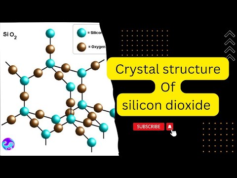
Silicon dioxide (SiO2) has a cubic crystal structure where silicon atoms occupy corner and face-centered positions, with oxygen atoms positioned between silicon atoms; each silicon atom is bonded to 4 oxygen atoms (coordination number 4), while each oxygen atom bridges 2 silicon atoms (coordination number 2), resulting in a unit cell containing 4 silicon atoms and 8 oxygen atoms.
Click to watch →

P Block Elements #10 | Carbon Family | Compounds of Silicon | Silica | Silicones |Silicates |Zeolite
11.6K
Silicon dioxide has an sp3 hybridized structure where each silicon atom bonds to four oxygen atoms in a tetrahedral geometry, forming a three-dimensional network. It exists in three crystalline forms: quartz (used in clocks), cristobalite (fluorescent lights), and tridymite (glass manufacturing). These forms interconvert at ~573°C. The alternating single and double bonds between Si and O atoms create resonance stabilization. SiO2 is chemically inert but reacts with HF, concentrated alkalis, and fluorine. Its applications include electronics (dielectric materials, capacitors), piezoelectric devices (watches, radios), chromatography (adsorbent), petroleum catalysis, and water purification.
Click to watch →
【2023重要問題集】259結晶の構造
1.2K
In the crystal structure of silicon dioxide (SiO2), each silicon atom is bonded to four oxygen atoms in a tetrahedral arrangement, and each oxygen atom bridges two silicon atoms. The distance between adjacent oxygen atoms (x) can be calculated using the relationship x = (2/3)√6 × r, where r is the Si-O bond length. This geometric relationship is derived by considering the crystal lattice as a cube with silicon at the center and oxygen atoms at alternate vertices, or alternatively by analyzing the regular tetrahedron formed by the oxygen atoms around each silicon atom.
Click to watch →

LE CRISTAL SE CONSTRUIT-IL UNIQUEMENT AVEC DES ATOMES ?
1.4K
Crystals are characterized by long-range order described by symmetry elements. Silica (SiO2) demonstrates polymorphism: the same SiO4 tetrahedra can form amorphous materials (sand, glass, opal) or crystalline quartz depending on symmetry arrangement. Quartz has hexagonal symmetry with channels at the atomic level corresponding to its external hexagonal form. Diamond and graphite are polymorphs of carbon with identical composition but different structures and properties, demonstrating that crystal structure depends on formation conditions (temperature, pressure, atmosphere) rather than composition alone.
Click to watch →
Deep Dive
The general concept of energy transduction (the conversion of mechanical energy to electrical energy and vice versa).

Electrical Machines - I Unit-01 Lec-01 || B.Tech 4th Semester AKTU 2nd year Machines-I Class | JE
1.7K
Electromechanical energy conversion is the process of converting electrical energy into mechanical energy and vice versa. This bidirectional conversion is the fundamental principle underlying all electrical machines, where electrical energy can be transformed into mechanical motion and mechanical motion can be transformed back into electrical energy.
Click to watch →

TRANSFORMAÇÃO DE ENERGIA | Cláudio e Gil
13.6K
Energy conversion can work in both directions: electrical energy can be converted to mechanical energy (motors), and mechanical energy can be converted to electrical energy (generators). The same device can function as either depending on the energy input and output.
Click to watch →

Canales Iónicos
2.9K
Transduction is the process by which one form of energy is converted into another - in sensory systems, mechanical energy is converted into electrical (neural) signals. This process occurs in all sensory systems, including touch, hearing, vision, and balance. The ability to transduce energy is fundamental to how organisms perceive and respond to their environment.
Click to watch →
Basics of Electromechanical Energy Conversion | Electrical Machines | Full lecture | Electrical
1.6K
Electromechanical energy conversion is the process of converting electrical energy into mechanical energy and vice versa. A device that converts electrical energy into mechanical energy is called a motor, while a device that converts mechanical energy into electrical energy is called a generator. This conversion occurs through a coupling medium of either an electric field or magnetic field.
Click to watch →
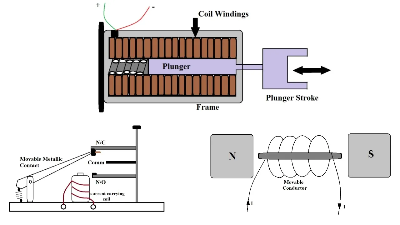
Electrical Machines | Electromechanical Energy Conversion Devices | Basic Concepts
3.7K
Electromechanical energy conversion involves transforming electrical energy into mechanical energy or vice versa, governed by the law of conservation of energy. The system comprises three components: electrical system, mechanical system, and coupling field. Devices are classified into three categories: transducers (for sensing and measurement), force-producing devices (for generating sudden motion), and continuous energy conversion devices (for bulk energy conversion). Transducers like microphones and loudspeakers operate on Fleming's rules, converting sound vibrations to electrical signals and vice versa.
Click to watch →
Prerequisite Knowledge
- Concept 01Fundamental concepts of mechanical oscillation, resonance, and natural frequency.
- Concept 02Basic electrical circuit theory, including voltage, alternating current (AC), and electrical charge.
- Concept 03The atomic structure of crystals, particularly the non-centrosymmetric arrangement of atoms in silicon dioxide (quartz).
- Concept 04The general concept of energy transduction (the conversion of mechanical energy to electrical energy and vice versa).
Subsequent Learning
- Step 01The integration of quartz crystals into feedback loops, specifically the Pierce oscillator circuit.
- Step 02Digital frequency division, explaining how a 32,768 Hz quartz oscillation is divided down to a 1 Hz pulse for digital and analog clocks.
- Step 03Temperature Compensation (TCXO/OCXO) techniques used to prevent frequency drift in high-precision timekeeping.
- Step 04Other industrial applications of piezoelectricity, such as in sonar, ultrasonic imaging, and micro-actuators.
Clock Function
Clock Function
0:00Playing Section
- 1
Explains quartz clock mechanism using piezoelectric effect.
- 2
Describes battery, circuit, and microchip detecting vibrations.
- 3
Details stepper motor pulses and cog rotation for ticking.
Silicon MEMS Resonators
While the piezoelectric effect in quartz crystals has dominated timekeeping for decades, Silicon Micro-Electro-Mechanical Systems (MEMS) resonators present a major technological alternative. Unlike quartz, which relies on the physical piezoelectric deformation of a crystal, MEMS resonators utilize electrostatic actuation of silicon microstructures. This alternative approach addresses key limitations of quartz, such as vulnerability to mechanical shock, larger physical size, and the inability to be integrated directly onto silicon microchips. MEMS technology allows for batch manufacturing alongside semiconductor circuits, offering superior shock resistance, smaller footprints, and lower power consumption, thereby challenging the necessity of quartz-based piezoelectricity in modern electronic timekeeping.
Deep Dive
The integration of quartz crystals into feedback loops, specifically the Pierce oscillator circuit.
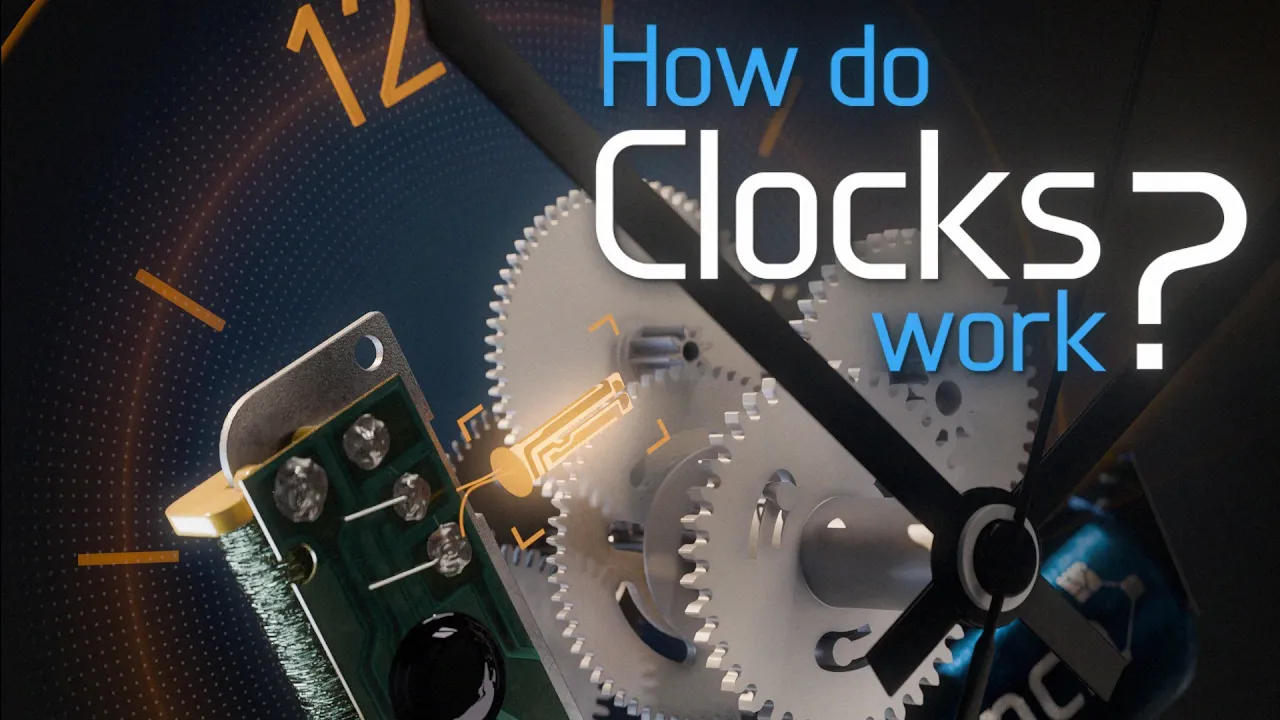
How do Digital and Analog Clocks Work?
629.4K
To create continuous oscillation in a quartz crystal, an integrated circuit with an inverter forms a feedback loop. When an inverter loops back on itself, its output continuously flips between 1 and 0 at very high speeds (a few picoseconds per cycle). Adding the crystal tuning fork and capacitors to this feedback path regulates the flipping rate based on the crystal's resonant frequency and the capacitors' charging/discharging cycles. For a wall clock, this produces 32,768 cycles per second (32.768 kHz), taking 30.52 microseconds per cycle.
Click to watch →
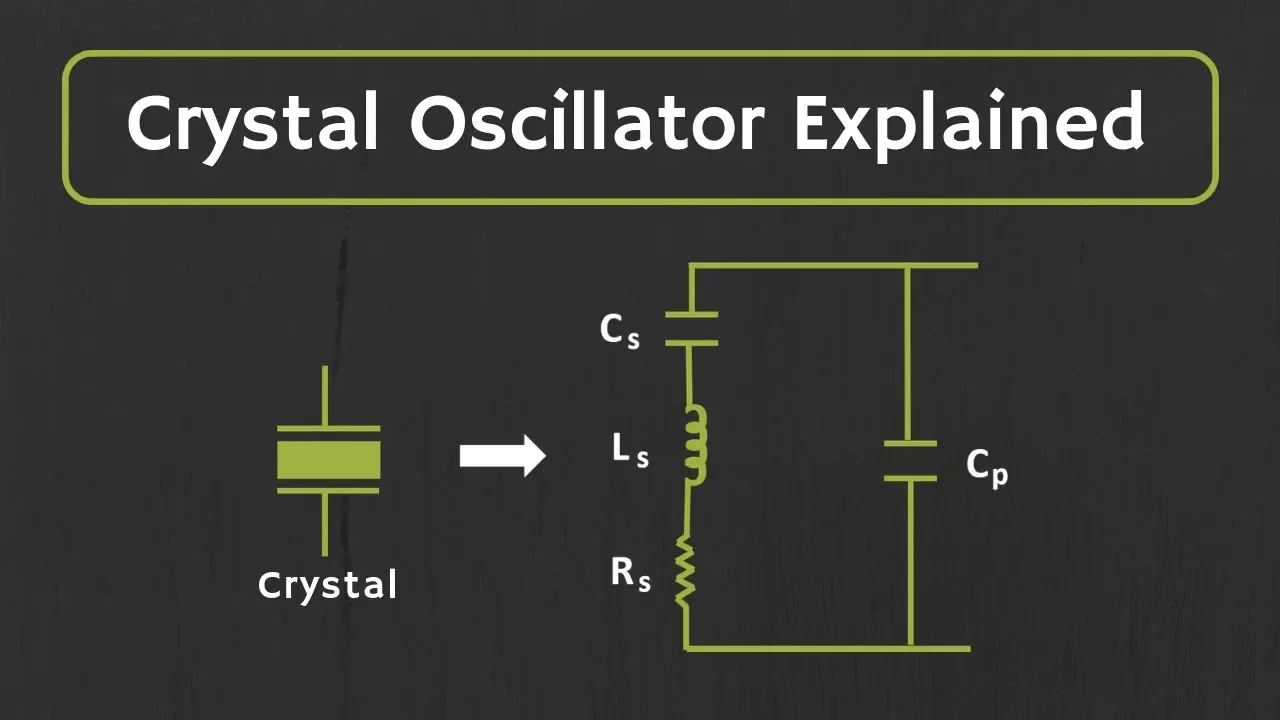
Crystal Oscillator Explained
435K
The Pierce oscillator uses a CMOS inverter with the crystal connected in parallel resonance mode. The crystal acts as an inductor, combining with capacitors C1 and C2 to form an LC tank circuit for frequency selectivity. A feedback resistor Rf (typically >1MΩ) connects input to output, forcing the CMOS inverter to operate in its linear region rather than switching mode. A series resistor Rs reduces overtone oscillations and improves start-up response. The Pierce oscillator produces square wave output, making it ideal for digital circuits, microcontrollers, and processors where internal resistors often replace external components.
Click to watch →

3 Simple Crystal Oscillator Circuits
23.3K
This section covers the first crystal oscillator circuit using a 74HC4 hex inverter chip. The Pierce oscillator creates oscillation by connecting the output to input via a 1MΩ resistor, creating an unstable state that causes continuous switching. Adding a crystal locks the oscillation to its resonant frequency (demonstrated with 4MHz, 8MHz, 16MHz, and 27.12MHz crystals). The 22pF capacitors provide phase shift, and a 220Ω resistor limits crystal current. Power connects to pins 14 and 7 with a 100nF decoupling capacitor. Unused inputs must be grounded. The circuit operates from 2-6V and produces square wave outputs suitable for digital clock applications.
Click to watch →

КАК СДЕЛАТЬ ГЕНЕРАТОР ЧАСТОТЫ. ГЕНЕРАТОР ПИРСА
105.3K
A quartz frequency generator can be built using the classic Pierce oscillator circuit, which consists of a single field-effect transistor and four supporting components (quartz resonator, two capacitors, and two resistors). The circuit operates on the principle of positive feedback, where a small initial impulse causes the system to oscillate and stabilize at the parallel resonance frequency of the quartz resonator. Key design considerations include minimizing parasitic parameters by keeping component leads and traces short, selecting appropriate capacitor values (10-100 pF, with lower frequencies requiring smaller capacitance), and choosing resistor values (100-2000Ω for R1, 0-100kΩ for R2) based on the quartz frequency. While homemade generators work, commercial quartz generators in metal cases provide more stable and accurate frequency output.
Click to watch →

#A193 Diseño, construcción y pruebas de un oscilador con cristal de cuarzo
575
A quartz crystal oscillator uses the piezoelectric effect of a quartz crystal to generate a highly stable frequency signal, where the crystal's mechanical resonance (with series and parallel resonances) provides superior frequency stability compared to LC oscillators; the circuit typically employs a Clapp oscillator configuration with a transistor, biasing resistors, and the crystal replacing the LC tank circuit, with proper biasing ensuring the base current doesn't affect the voltage divider for thermal stability.
Click to watch →
Deep Dive
Digital frequency division, explaining how a 32,768 Hz quartz oscillation is divided down to a 1 Hz pulse for digital and analog clocks.
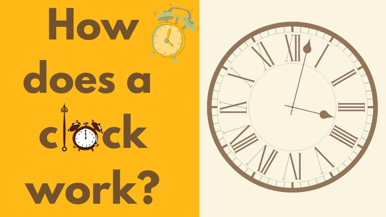
How Does a Clock work ? | Crystal oscillator | Flip-Flop | Lavet type motor
169.2K
Clock circuits use digital electronics to convert high-frequency oscillator signals into precise one-second pulses. A 32,768 Hz crystal oscillator produces exactly 32,768 oscillations per second. This number equals 2^15, making it ideal for binary division. D flip-flop circuits are used to count oscillator cycles - each flip-flop halves the input frequency. Sending the oscillator pulse into a D flip-flop produces an output at half the input frequency (time per cycle doubles). Feeding this output into another flip-flop halves the frequency again. By cascading 15 flip-flops in sequence, the 32,768 Hz signal is reduced to exactly 1 Hz (one pulse per second), providing the precise timing signal needed for clock operation.
Click to watch →
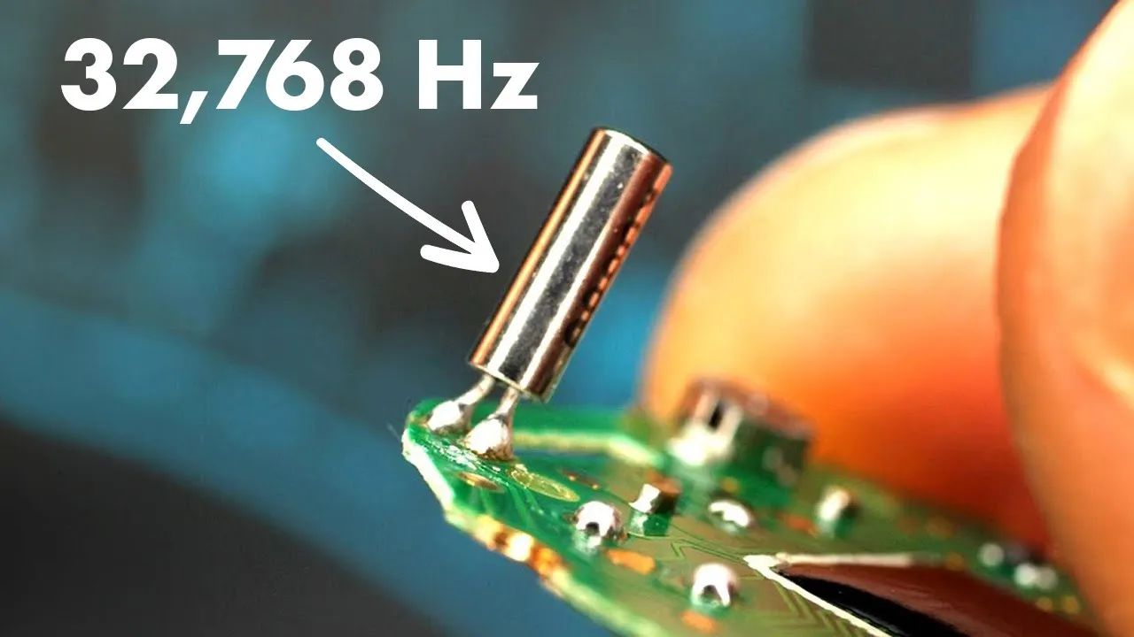
How a quartz watch works - its heart beats 32,768 times a second
8.4M
A chain of 15 flip-flops converts the 32,768 Hz quartz signal to 1 Hz through successive binary division. Each flip-flop divides the incoming frequency by two, creating a cascading effect where each stage produces exactly half the frequency of the previous one. This elegant binary approach enables precise timekeeping with minimal electronic complexity.
Click to watch →
Время - Владимир Сурдин.
148.6K
The 32,768 Hz oscillation from the quartz crystal is divided by powers of 2 to produce 1 Hz (one cycle per second). This 1 Hz signal drives the clock's timekeeping mechanism, which then generates 60 Hz for minutes and 3,600 Hz for hours. The division process is performed electronically, allowing precise timekeeping without mechanical components. This frequency division is fundamental to all quartz-based timekeeping.
Click to watch →
![Zegarek radzieckiego Bonda [TOWARY MODNE 89]](https://i.ytimg.com/vi/44DdV7DlCWs/maxresdefault.jpg)
Zegarek radzieckiego Bonda [TOWARY MODNE 89]
111.8K
Digital watches used a quartz oscillator as their timekeeping heart. The quartz crystal vibrated at a precise frequency of 32,768 Hz (2 to the power of 15). This high-frequency signal was fed through a series of 15 frequency dividers, with the final output being 1 Hz (one pulse per second). Intermediate frequencies like 2,048 Hz were also used for other functions. This frequency division system provided the stable timing reference needed for accurate timekeeping in digital watches.
Click to watch →

Rozmowa z Jankiem - Elektroniczne zegary #RS Elektronika #242
62.8K
Electronic clocks owe their existence to the quartz resonator invention, which enables high accuracy. Quartz serves as the synchronizing element, functioning as a generator of rectangular pulses with constant frequency. When stimulated at its natural vibration frequency, quartz maintains that frequency with high accuracy, with temperature being the primary factor affecting this frequency. Initially, quartz resonators operated at high frequencies (1 MHz or 10 MHz) because these were easiest to manufacture with high stability. Digital circuits contain frequency dividers, allowing these high frequencies to be divided by powers of ten to obtain 1 Hz or other multiples. This division does not reduce accuracy - the 1 Hz signal remains as accurate as the original high-frequency quartz source. This principle enables building clocks with high stability and accuracy by simply counting pulses from a 1 Hz, 10 Hz, or 100 Hz generator.
Click to watch →
Deep Dive
Temperature Compensation (TCXO/OCXO) techniques used to prevent frequency drift in high-precision timekeeping.

#336 How to get Precise Timing and Frequency to our Lab. From Crystals, TCXO, OCXO to GPSDO, BG7TBL
64.2K
Precision timing demands progressively sophisticated oscillator technologies. Temperature Compensated Crystal Oscillators (TCXOs) address temperature-induced drift by incorporating temperature sensors and compensation circuits, achieving 0.5 ppm stability (10 kHz at 10 GHz). Oven Controlled Crystal Oscillators (OCXOs) eliminate temperature effects entirely by heating the crystal to stable temperatures above ambient (70+°C), achieving 300 Hz stability at 10 GHz. However, neither provides long-term frequency calibration. Disciplined oscillators solve this by continuously comparing the local oscillator's phase against a more precise external reference, applying tiny corrections to maintain long-term accuracy while preserving short-term stability. This hybrid approach combines the best attributes of both worlds.
Click to watch →
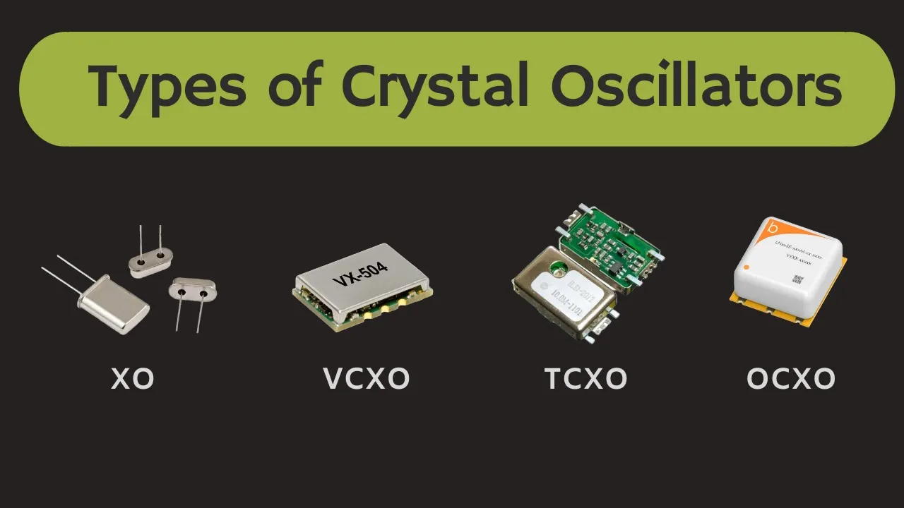
Types of Crystal Oscillators Explained | TCXO, OCXO, VCXO Explained
16K
Crystal oscillators utilize the piezoelectric effect of quartz to generate precise electrical signals at specific frequencies. Four main types exist: normal XO, TCXO, OCXO, and VCXO. Crystal oscillators face two primary stability challenges: aging (±1-5 ppm/year frequency drift) and temperature-induced frequency shifts. TCXOs achieve temperature stability of ±0.2-2 ppm over 0-50°C using thermistors, voltage dividers, difference amplifiers, and polynomial correction circuits to adjust varactor diodes. OCXOs provide exceptional stability of 1-100 ppb by maintaining crystals at constant temperature using internal ovens operating at turning points above ambient (60-70°C). Both technologies enable precision applications in telecommunications, instrumentation, and military systems despite their respective trade-offs in power consumption, cost, and warm-up time requirements.
Click to watch →
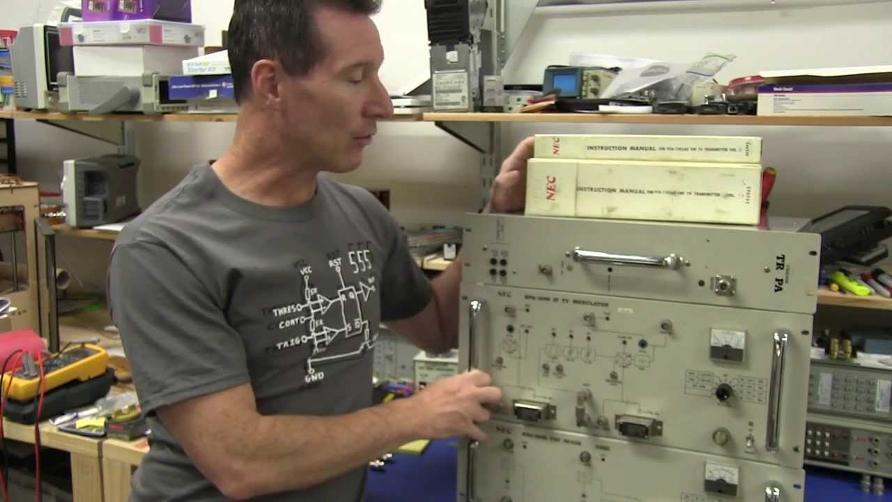
EEVblog #574 - NEC Analog TV IF Modulator Teardown
148.2K
The TCXO uses temperature compensation with two thermosensors and a transistor (instead of a diode) to compensate for crystal frequency drift with temperature. The compensation works by varying the impedance between base and collector based on temperature sensor readings. The TCXO provides frequency stability essential for broadcast transmission, with the documentation showing aging characteristics of ±2 PPM over time. The technology represents a balance between the stability of oven-controlled oscillators (OCXO) and the simplicity of temperature-compensated designs.
Click to watch →
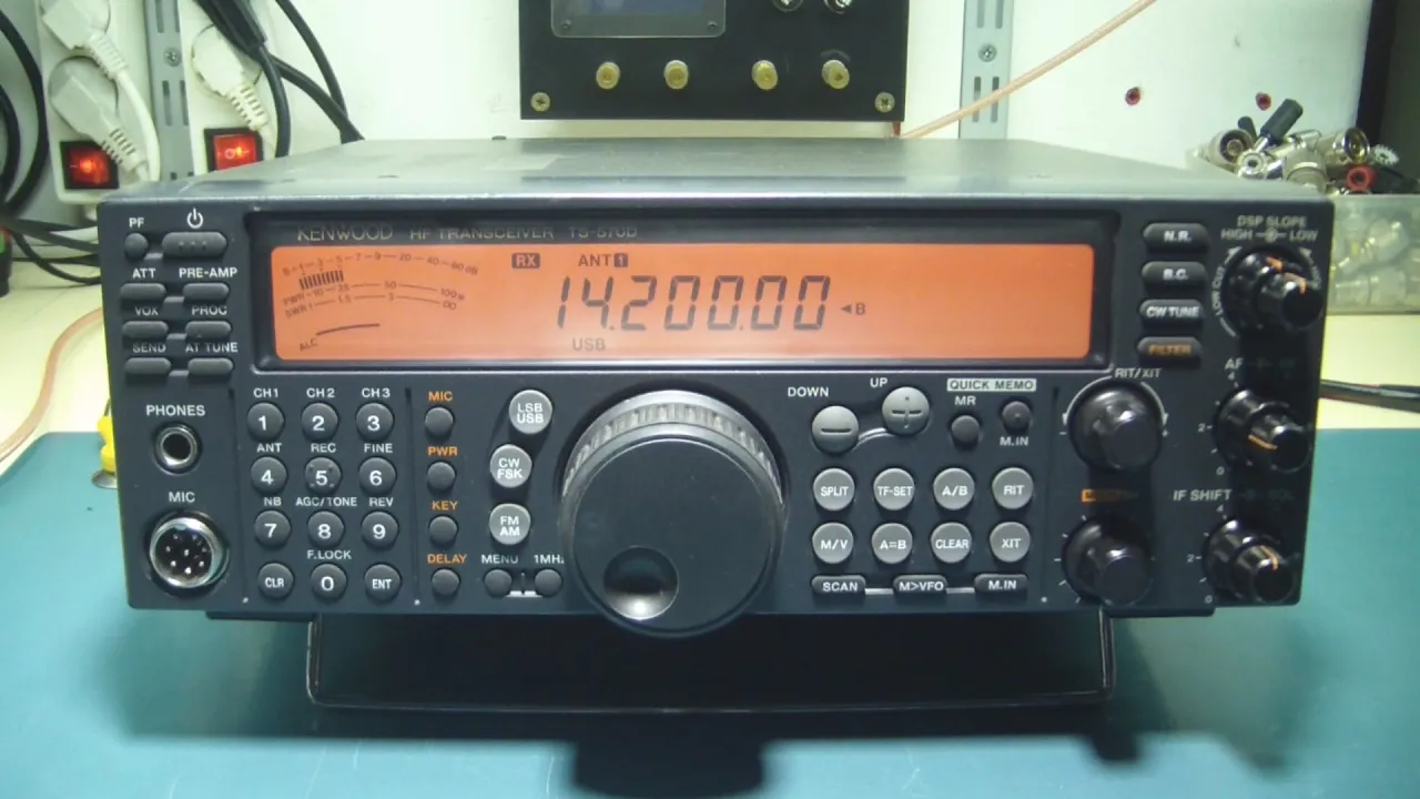
Kenwood ts 570D Reception Problems And TCXO Installation
5.9K
TCXOs are designed to compensate for temperature variations in crystal oscillators. When the radio is cold, the TCXO may produce a slightly different frequency than when it is warm. The technician allows the radio to warm up and then retests the frequency. The TCXO should stabilize to a consistent frequency after the radio reaches operating temperature. After powering on the radio, the TCXO requires time to stabilize to its operating temperature. The technician allows the radio to warm up for approximately 1.5 hours before final frequency verification. During this time, the frequency may drift as the TCXO reaches thermal equilibrium.
Click to watch →
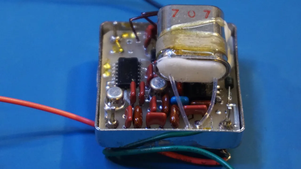
Inside an Oven Controlled Crystal Oscillator (OCXO)
10.2K
Oven Controlled Crystal Oscillators (OCXOs) provide significantly better temperature stability than standard crystal oscillators by heating the crystal to a constant temperature using a controlled oven, which prevents frequency drift caused by ambient temperature changes; this makes OCXOs essential for precision measurement equipment like frequency counters where measurement accuracy depends on the reference oscillator's stability.
Click to watch →
Deep Dive
Other industrial applications of piezoelectricity, such as in sonar, ultrasonic imaging, and micro-actuators.
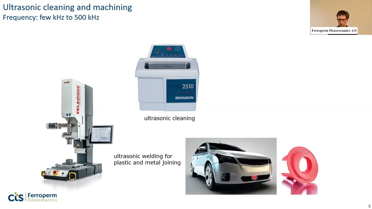
Applications of Piezoelectric Materials - Ferroperm Piezoceramics Webinars 2022
171
Piezoelectric materials convert between mechanical and electrical energy through direct and converse effects, forming the basis for over 20 diverse applications. The direct effect converts mechanical stress into electrical charge, powering ignition systems and pressure sensors, while the converse effect converts electrical signals into mechanical vibrations, enabling devices like buzzers and loudspeakers. Applications are categorized as resonant (exploiting high efficiency at resonance frequencies for filters, sensors, and ultrasonic devices) or non-resonant (operating in linear ranges for actuators and positioning systems). Industrial ultrasonic processing leverages high-frequency vibrations (kHz to 500 kHz) for enhanced manufacturing: ultrasonic cleaning removes contaminants through standing waves, ultrasonic welding joins materials via frictional heating, and ultrasonic cutting machines hard materials with abrasive slurries. Ultrasound dramatically accelerates chemical reactions, achieving 95% completion in 1.5 hours versus 88% in 18 hours without ultrasound. Underwater acoustics represents one of the most mature piezoelectric applications, enabling marine exploration through fish-finding systems, mapping applications capable of reaching depths exceeding 11 kilometers, and positioning systems functioning as underwater GPS. Ultrasonic flow measurement provides non-invasive methods including time-of-flight, Doppler, and vortex systems for determining fluid velocity. In medical diagnostics, ultrasound imaging operates from 100 kHz to several MHz, enabling visualization of internal structures including fetal development, with advanced 3D imaging and vector flow imaging providing detailed blood flow visualization.
Click to watch →

Piezoelectric transducer | Wikipedia audio article
115
Piezoelectric devices generate high voltages from mechanical stress—quartz can produce thousands of volts. Applications include electric cigarette lighters, gas stove igniters, and DARPA energy harvesting projects embedding generators in soldiers' boots. Piezoelectric transformers use acoustic coupling instead of magnetic coupling, achieving step-up ratios over 1000:1. Sensors detect sound, pressure, and vibrations through force-induced charge changes—microphones, guitar pickups, medical ultrasound transducers, and automotive knock sensors. Actuators provide extreme precision positioning—multi-layer ceramics achieve sub-micrometer strokes for loudspeakers, laser alignment, and inkjet printing. Common rail diesel engines use piezoelectric fuel injectors. Quartz oscillators serve as frequency standards in clocks, radios, and computers. Energy harvesting from human movement in dance floors and train stations demonstrates practical applications, with studies estimating 1.1 MWh annual harvesting potential from optimized piezoelectric tile deployment. Piezoelectric motors exploit dual orthogonal vibration modes with 90-degree phase differences, creating elliptical contact paths for frictional force—traveling wave motors for camera autofocus, inchworm motors for linear motion, and stick-slip motors for precision positioning.
Click to watch →

Piezoelectric crystal | Wikipedia audio article
112
Piezoelectric technology spans diverse applications from industrial to medical fields. Direct piezoelectricity generates thousands of volts—used in cigarette lighters where spring-loaded hammers strike piezoelectric crystals to ignite gas. Energy harvesting applications include piezoelectric generators in soldiers' boots (abandoned due to impracticality), dance floors powering club lighting, highway piezoelectric materials powering streetlights, and tire-mounted generators. Piezoelectric transformers use acoustic coupling instead of magnetic coupling: input voltage creates alternating stress in piezoelectric bars at resonant frequencies (100 kHz-1 MHz), generating higher output voltages across other sections. Step-up ratios exceeding 1000:1 have been demonstrated. Piezoelectric sensors transform physical dimensions into forces through longitudinal, transversal, or shear detection modes. Sound detection is most common—used in microphones and guitar pickups. Piezoelectric microbalances serve as sensitive chemical and biological sensors. Actuators exploit the converse effect: high electric fields produce tiny crystal deformations enabling extreme precision positioning. Multi-layer ceramics with layers under 100 micrometers achieve high electric fields at voltages under 150 V. Applications include loudspeakers, piezoelectric motors (traveling wave, ultrasonic, stick-slip types) for camera autofocus and precision positioning, laser mirror alignment, acousto-optic modulators for laser frequency tuning, inkjet printer heads, and diesel engine fuel injectors. Piezoelectric surgery uses 25-29 kHz frequencies causing 62-210 micrometer micro-vibrations to cut mineralized tissue without damaging neurovascular tissue. Piezoelectric activation of oocytes combined with intracytoplasmic sperm injection improves fertilization outcomes in cases of previous total fertilization failure. Cambridge researchers discovered piezoelectric thin films can function as efficient antennas when subjected to asymmetric excitation.
Click to watch →

Cómo extraer electricidad de los cristales - Ashwini Bharathula
18.4K
Piezoelectric materials convert mechanical energy (pressure, sound, vibrations) into electricity and vice versa. Discovered by Pierre and Jacques Curie in 1880, this phenomenon occurs when crystals lack a center of symmetry. When compressed, atoms shift, creating charge separation that generates voltage. The inverse effect causes crystals to deform under electrical fields. First used in WWI sonar for submarine detection, piezoelectricity now powers watches, speakers, inkjet printers, and medical imaging. Biological materials like DNA, bone, and silk also exhibit this property. Emerging applications include energy harvesting from footsteps and movements for powering devices.
Click to watch →
🧪 PIERRE CURIE y el fatídico 19 de abril de 1906
10.1K
The Curie brothers discovered piezoelectricity while studying piroelectricity, finding that certain crystals generate electrical charges when subjected to mechanical stress. This phenomenon occurs when crystals develop electrical polarization under tension or compression. The effect operates bidirectionally: mechanical stress produces electricity (direct effect), and electrical current causes mechanical deformation (inverse effect). Applications include lighters, hydrophones, sustainable energy generation from foot traffic and vehicle movement, and SONAR technology developed by Paul Langevin in 1917. These transducers convert between electrical and ultrasonic energy, enabling applications in microphones, speakers, airbags, parking sensors, and medical imaging.
Click to watch →
Clock Function
Clock Function
0:00- 1
Explains quartz clock mechanism using piezoelectric effect.
- 2
Describes battery, circuit, and microchip detecting vibrations.
- 3
Details stepper motor pulses and cog rotation for ticking.
Silicon MEMS Resonators
While the piezoelectric effect in quartz crystals has dominated timekeeping for decades, Silicon Micro-Electro-Mechanical Systems (MEMS) resonators present a major technological alternative. Unlike quartz, which relies on the physical piezoelectric deformation of a crystal, MEMS resonators utilize electrostatic actuation of silicon microstructures. This alternative approach addresses key limitations of quartz, such as vulnerability to mechanical shock, larger physical size, and the inability to be integrated directly onto silicon microchips. MEMS technology allows for batch manufacturing alongside semiconductor circuits, offering superior shock resistance, smaller footprints, and lower power consumption, thereby challenging the necessity of quartz-based piezoelectricity in modern electronic timekeeping.
Fundamental concepts of mechanical oscillation, resonance, and natural frequency.
Basic electrical circuit theory, including voltage, alternating current (AC), and electrical charge.
The atomic structure of crystals, particularly the non-centrosymmetric arrangement of atoms in silicon dioxide (quartz).
The general concept of energy transduction (the conversion of mechanical energy to electrical energy and vice versa).
The integration of quartz crystals into feedback loops, specifically the Pierce oscillator circuit.
Digital frequency division, explaining how a 32,768 Hz quartz oscillation is divided down to a 1 Hz pulse for digital and analog clocks.
Temperature Compensation (TCXO/OCXO) techniques used to prevent frequency drift in high-precision timekeeping.
Other industrial applications of piezoelectricity, such as in sonar, ultrasonic imaging, and micro-actuators.
67.9K views746likes1:55@SHArPEdgeGlobalOriginal Release: 2013-07-09
clock as an application of piso electric effect quartz crystals are nowadays used in clocks and watch to keep time now let us discuss the concept behind tick and talk functionality of the clock the clock circuitry consists of a battery quartz crystal oscillator mic microchip stepping motor and cogs now we will see the working of the clock circuitry in detail the electrons flowing from the battery electrifies the quartz crystal when quartz crystal is electrified it begins to vibrate or oscillate due to one of its properties called piso electric effect the microchip connected detects the number of vibrations in the Crystal and will calculate how many times the crystal should vibrate this means that every time the microchip detects a fixed number of vibrations around 33,000 it will send an electrical pulse to the stepping motor in the stepper motor due to the electrical pulse from microchip the polarity of the solenoid changes and as the polarity of the solenoid changes it causes the magnet to rotate which turns the cogs every second this is how the tick tock in the Clock Works
Up Next

25:09
How Atomic Clocks Work: Inside the HP 5061A Cesium Clock
@CuriousMarc
446.5K views•2020-03-20

12:53
21cm Hyperfine Transition in Neutral Hydrogen: Radio Astronomy Basics
@AaronRobertParsons
12.4K views•2011-10-13

32:32
NMR Spin Physics I: Zeeman Effect, Resonance Condition & Larmor Frequency
@nptel-indianinstituteofsci8064
2.3K views•2024-01-17

27:14
Entropy and the Second Law of Thermodynamics Explained
@veritasium
27.5M views•2023-07-01
Related Study Plans & Knowledge Roadmaps
Structured learning paths in Physics
physics
Nuclear Physics (Decay, Fission & Reactors)
01Atomic Structure and the Binding Force
02Radioactive Decay and Half-Life
03Nuclear Fission Mechanics and Chain Reactions
+ 2 more learning modules
12h5 modules
Explore Roadmap
physics
Soft Matter (Polymers, Colloids & Rheology)
01Foundations of Soft Matter & Thermal Forces
02Polymer Physics and Macromolecules
03Colloids, Surfactants, and Self-Assembly
+ 2 more learning modules
38h5 modules
Explore Roadmap
physics
Analytical Mechanics: Lagrangian & Hamiltonian
01Mathematical Foundations: Calculus of Variations
02From Newtonian Mechanics to Constraint Dynamics
03The Principle of Least Action & Lagrangian Mechanics
+ 3 more learning modules
28h6 modules
Explore Roadmap
physics
General Relativity (Spacetime & Cosmology)
01Foundations of Relativity: Special Relativity
02The Geometry of Spacetime: Equivalence Principle & Curvature
03Einstein's Field Equations: The Mathematics of Gravity
+ 2 more learning modules
55h5 modules
Explore Roadmap