RTK (Real-Time Kinematic) technology improves GPS accuracy from meter-level to centimeter-level by using corrections from a surveyed base station located within approximately 20 miles of the rover. Since GPS signals travel through the atmosphere and experience delays that vary with weather conditions and time of day, causing position estimation errors, RTK applies these corrections to account for atmospheric distortions and inherent GPS system errors, effectively sharpening the 'fuzzy tape measure' of standard GPS positioning.
Centimeter-Level GPS: How RTK Corrections Work
Added:Deep Dive
Basic GNSS/GPS operational principles, specifically how trilateration and time-of-flight calculations are used to determine a receiver's position.

GPS mathematics
19.7K
GPS positioning uses trilateration, calculating distances from multiple satellites to determine location. Given satellite positions and signal travel times, multiply each time by signal speed (2 m/s) to find radii: 2s × 2m/s = 4m for satellite A, 1s × 2m/s = 2m for satellite B. The receiver lies at the intersection of circles centered at each satellite with these radii. This geometric approach transforms time-of-flight measurements into spatial coordinates, forming the fundamental principle behind global navigation satellite systems.
Click to watch →
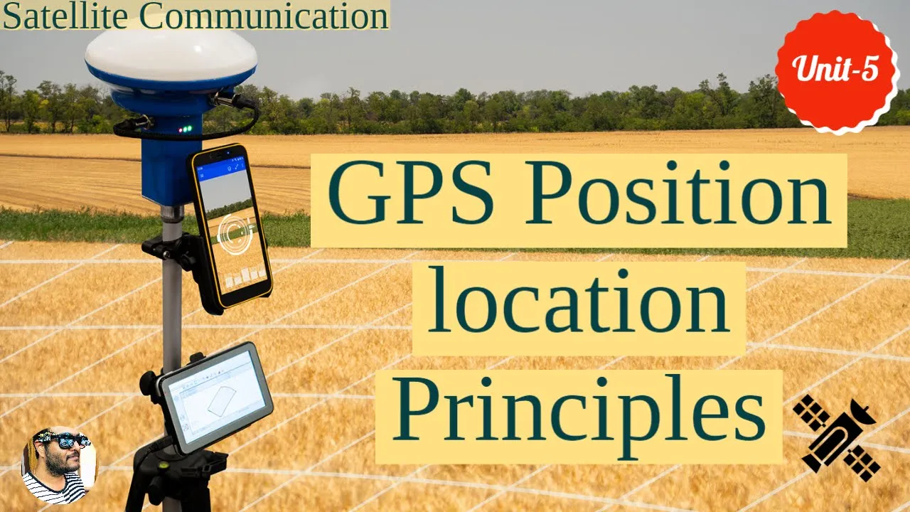
GPS position location principles || Trilateration method in GPS || Position determination
18.3K
GPS determines receiver position using trilateration, which requires measuring distances from the receiver to at least three satellites. Each satellite transmits signals modulated by either P-code (for military/security applications) or C/A-code (for civilian use). Since the 1980s, both satellites and receivers use atomic clocks for precise time synchronization. The receiver calculates distances to three satellites using ephemeris data (orbital positions), then solves the intersection of three spheres defined by these distances to determine the exact coordinates of the unknown point (receiver location).
Click to watch →

GNSS
3.5K
This section explains the fundamental principles of how GNSS calculates position. Each GPS satellite transmits two signals: L1 and L2, with different frequencies and wavelengths. L1 carries both C/A code (Coarse/Acquisition) and P code (Precision), while L2 only carries P code. The C/A code enables rapid signal acquisition but provides lower precision, while P code is used by authorized users for higher accuracy. Receivers are classified by precision: navigation receivers use C/A code achieving ~10 meters, topographic receivers record raw data including phase observations achieving <3 meters, and geodetic receivers record L1 and L2 phase data achieving centimeter-level precision after post-processing. Positioning works through trilateration, where the receiver calculates distances to at least four satellites by comparing transmission and reception times using the speed of light (300,000 km/second). This provides four equations to solve for four unknowns: the three position coordinates and the receiver's clock error. More visible satellites improve accuracy, and the system can derive additional information like velocity and time of arrival.
Click to watch →

Como funciona o GPS? Satélites, trilateração e precisão: entenda o GPS de uma vez
119K
GPS determines position using trilateration, not triangulation. Each satellite continuously broadcasts radio signals containing its precise location and transmission time. The receiver measures how long the signal took to arrive, knowing radio waves travel at light speed. This time measurement calculates distance to each satellite. Since position requires three dimensions (latitude, longitude, altitude), the receiver needs signals from at least four satellites to solve for the exact intersection point where all calculated distances converge.
Click to watch →
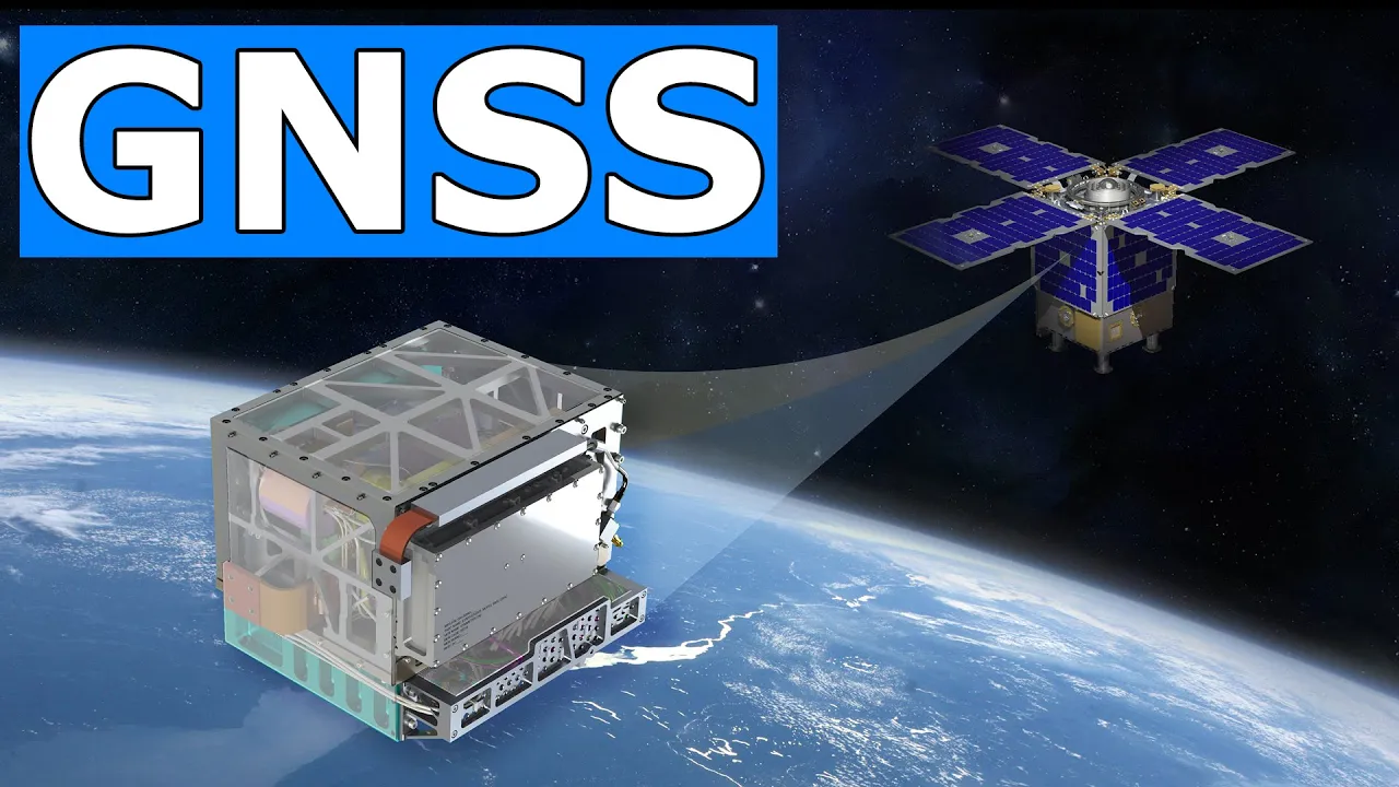
✅ Basics of GNSS Explained For Pilots | GNSS & GPS (2023)
46.1K
GNSS works on the principle of trilateration, where satellites transmit signals on different frequencies (L1 and L2) to account for ionospheric effects. Each signal contains navigation messages including satellite position (ephemeris), atomic clock time stamps, almanac data, and ionosphere information. By calculating the time difference between transmission and reception, multiplied by the speed of light, the receiver determines its distance from each satellite. This process is repeated simultaneously with multiple satellites to determine 3D position.
Click to watch →
Deep Dive
Common sources of satellite positioning errors, particularly how ionospheric and tropospheric atmospheric layers distort signal propagation.
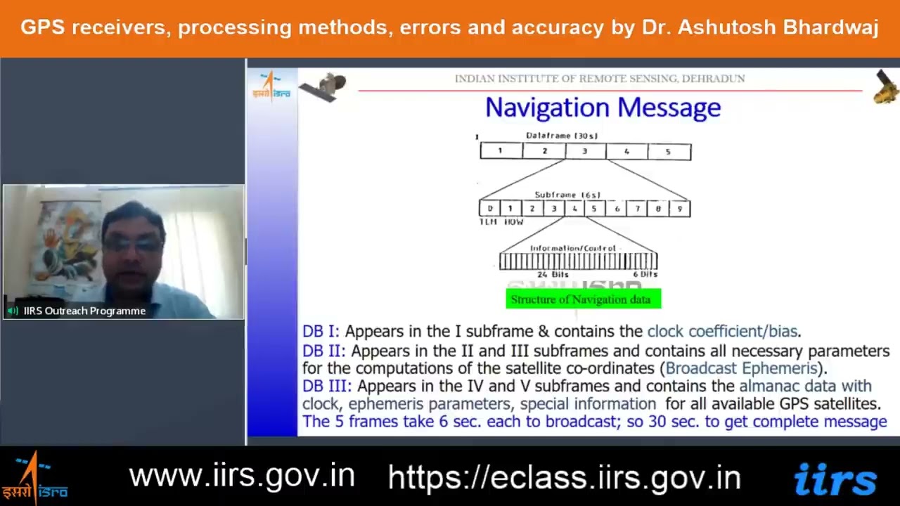
GPS receivers, processing methods, errors and accuracy by Dr. Ashutosh Bhardwaj
141
GNSS positioning errors arise from multiple sources: satellite clock errors, orbital (ephemeris) errors, atmospheric delays (ionosphere and troposphere), multipath reflections, and receiver noise. Atmospheric delays are corrected through differential techniques and standard models (Hopfield/Saastamoinen). Tropospheric delays range from 2m (zenith) to 30m (low elevation) depending on temperature, pressure, and humidity. Ionospheric delays are the largest error source after human factors, proportional to electron content and inversely proportional to frequency squared. Defense receivers using dual frequencies can correct ionospheric errors, while civilian receivers use new signals like L1C for partial compensation.
Click to watch →

Gate GE 2024 - GNSS | Class 4| DGPS | SOURCES OF ERRORS | GAGAN |
288
GPS positioning errors stem from multiple systematic sources: ionospheric and tropospheric propagation delays cause signal bending and slowing; satellite clock drift introduces timing errors translating to meter-scale position errors; multipath errors occur when signals reflect off surfaces before reaching receivers. These errors affect all GPS receivers similarly and form the foundation for differential correction techniques. GAGAN (GPS Aided Geo-Augmented Navigation) is India's regional satellite-based augmentation system comprising eight reference stations across major cities with a master control center in Bengaluru. It broadcasts correction data via geostationary satellites, providing centimeter-level accuracy for aviation and critical navigation applications across India.
Click to watch →

#3 - Emisje i propagacja
28.8K
Tropospheric propagation extends VHF/UHF range beyond line-of-sight through atmospheric refraction. Tropospheric ducting occurs when temperature inversions create 'ducts' trapping signals, enabling communications hundreds or thousands of kilometers away. This phenomenon is most common in late summer/early autumn and near sunrise/sunset. Sporadic E propagation uses ionized patches in the E region to reflect VHF signals, enabling long-distance communications on frequencies that would normally be blocked. The ionosphere consists of D, E, F1, and F2 layers that form and change based on solar radiation. At night, the D layer disappears, affecting which frequencies can be reflected. Solar activity (sunspots, solar flares) affects propagation, particularly on shortwave bands.
Click to watch →
Видео инструкция Спутниковая геодезия 1ч
1.9K
Major error sources include satellite clock errors, orbit errors, ionospheric delay, tropospheric delay, multipath effects, and electromagnetic interference. Geometric Dilution of Precision (GDOP) describes how satellite geometry affects accuracy—spread satellites improve precision. Ionospheric correction uses Klobuchar model (single-frequency, ~20 km) or dual-frequency elimination. Tropospheric correction uses Saastamoinen model. Single-frequency systems limited to 20 km baselines; dual-frequency systems handle 1000 km.
Click to watch →

πZZ∀MAT Coloquio: ¿ Cómo funciona un GPS y qué matemáticas hay detrás ?
243
GNSS positioning accuracy is affected by multiple error sources: (1) Ionospheric error (20-200 meters) from ionized particles in the upper atmosphere; (2) Tropospheric error (2-10 meters) from water vapor and dry air in the lower atmosphere; (3) Satellite clock errors (up to 10 meters) despite atomic clocks; (4) Ephemeris errors (1-5 meters) from satellite position uncertainties; (5) Multipath error (up to 20 meters) from signal reflections off surfaces; (6) Receiver oscillator errors (up to 100 meters). These errors are corrected through various techniques to achieve usable accuracy.
Click to watch →
Deep Dive
The conceptual difference between code-phase measurements (standard GPS) and carrier-phase measurements (which track the actual signal wave).

Global Positioning Basics - 4 End User Segment
7.4K
GPS receivers calculate satellite distances using two ranging methods: code phase and carrier phase. Code phase ranging analyzes pseudo-random noise (PRN) codes—unique 1000-byte sequences transmitted by each satellite. Receivers compare incoming signals against stored databases to identify satellites and measure time offsets, then apply the velocity equation (distance = speed × time) using the speed of light. This achieves approximately 3-meter resolution. Carrier phase ranging uses the higher-frequency carrier wave (1575.42 MHz vs. 1 MHz message rate), achieving 19-centimeter wavelengths and theoretical 2-millimeter resolution. However, carrier phase introduces challenges: phase ambiguity (determining partial wavelengths) and cycle ambiguity (counting whole wavelengths without two-way communication). High-accuracy receivers often combine both methods—using code phase for coarse positioning and carrier phase for fine-tuning.
Click to watch →

GPS Applications - Lecture and Questions Jan. 28
939
GPS calculates distance by measuring time differences between signal transmission and reception. Code-based measurements use the pseudorandom codes to determine signal travel time. Carrier phase measurements track the actual carrier wave cycles, achieving approximately 20 centimeter accuracy (L1 wavelength 24.4 cm, L2 wavelength 19 cm). Carrier phase can achieve sub-centimeter accuracy if the receiver can determine the precise phase angle. The Nevada Geodetic Lab uses carrier phase measurements with precise codes on L2 for high-accuracy geodetic applications.
Click to watch →

GNSS Chapter 3 - GNSS Positioning Concept
176
Phase observations have much higher precision than code observations because phase measures the signal at the carrier frequency (wavelength ~20-24 cm), while code observations are modulated at lower frequencies (wavelength ~300-30 m). Phase precision is approximately 1% of wavelength (~2 mm), while code precision is ~1% of 300 m (~3 m). Code observations use group velocity (signal envelope speed), while phase observations use phase velocity (carrier wave speed), which differ due to atmospheric effects.
Click to watch →

RSGIS L22: DGPS, SBAS, RTK, PPS: How GPS Becomes More Accurate
261
GNSS positioning uses two ranging methods: code-based ranging and carrier-based ranging. Code-based ranging measures distance using the pseudo-random code transmitted by satellites, achieving typical accuracy of 5-10 meters. Carrier-based ranging uses the carrier wave's phase to measure distance with millimeter-to-centimeter precision. The carrier wave is a continuous sinusoidal electromagnetic wave defined by amplitude, frequency, and phase. The key challenge is integer ambiguity—the unknown whole number of carrier cycles between satellite and receiver—which must be resolved using algorithms like double differencing, Kalman filtering, and Lambda methods.
Click to watch →

GPS RTK Surveying Workshop
237.6K
RTK uses both the PRN (pseudo-random number) and carrier phase measurements. The carrier phase is the phase of the radio signal's carrier wave. By measuring the phase difference between the expected and received signal, the receiver can compute the distance to the satellite with much greater precision than using the PRN alone.
Click to watch →
Deep Dive
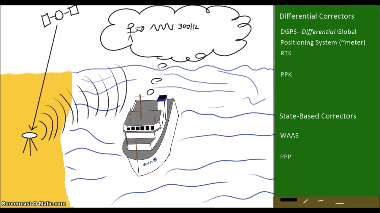
The fundamental concept of Differential GPS (DGPS), where a stationary base station is used to calculate errors for a nearby mobile receiver.
5 Minute Modules - GPS, Part 3
1.9K
Differential GPS works by placing a GPS receiver at a fixed, precisely known location called a base station. Since the base station's true position is known, any difference between its actual position and what the GPS signal indicates represents the positioning error. When a mobile receiver (rover) is close enough to this base station, it is assumed that the same atmospheric and other errors affect both locations similarly. This allows the rover to remove these common errors from its position calculation, improving accuracy.
Click to watch →

Building an affordable differential GPS positioning system
2.6K
Differential GPS (DGPS) exploits the fact that major GPS errors are spatially correlated - errors at one location are highly correlated with nearby locations. A reference station with known true position measures its own GPS errors, then transmits these per-satellite corrections to a moving rover. The rover applies these corrections to its pseudo-ranges, resulting in improved position estimates. DGPS requires knowing the absolute true position of the reference station for absolute positioning, though relative positioning can work without this knowledge.
Click to watch →

Open Source Archaeological Geophysics
1K
Differential GPS improves accuracy by using a base station that measures errors common to all nearby units. The base station communicates these error corrections to a mobile unit, allowing the mobile unit to compensate for its own measurements. This technique achieves 1-2 meter accuracy compared to standard GPS accuracy.
Click to watch →
b GPS Receivers, Processing methods Error Accuracy
214
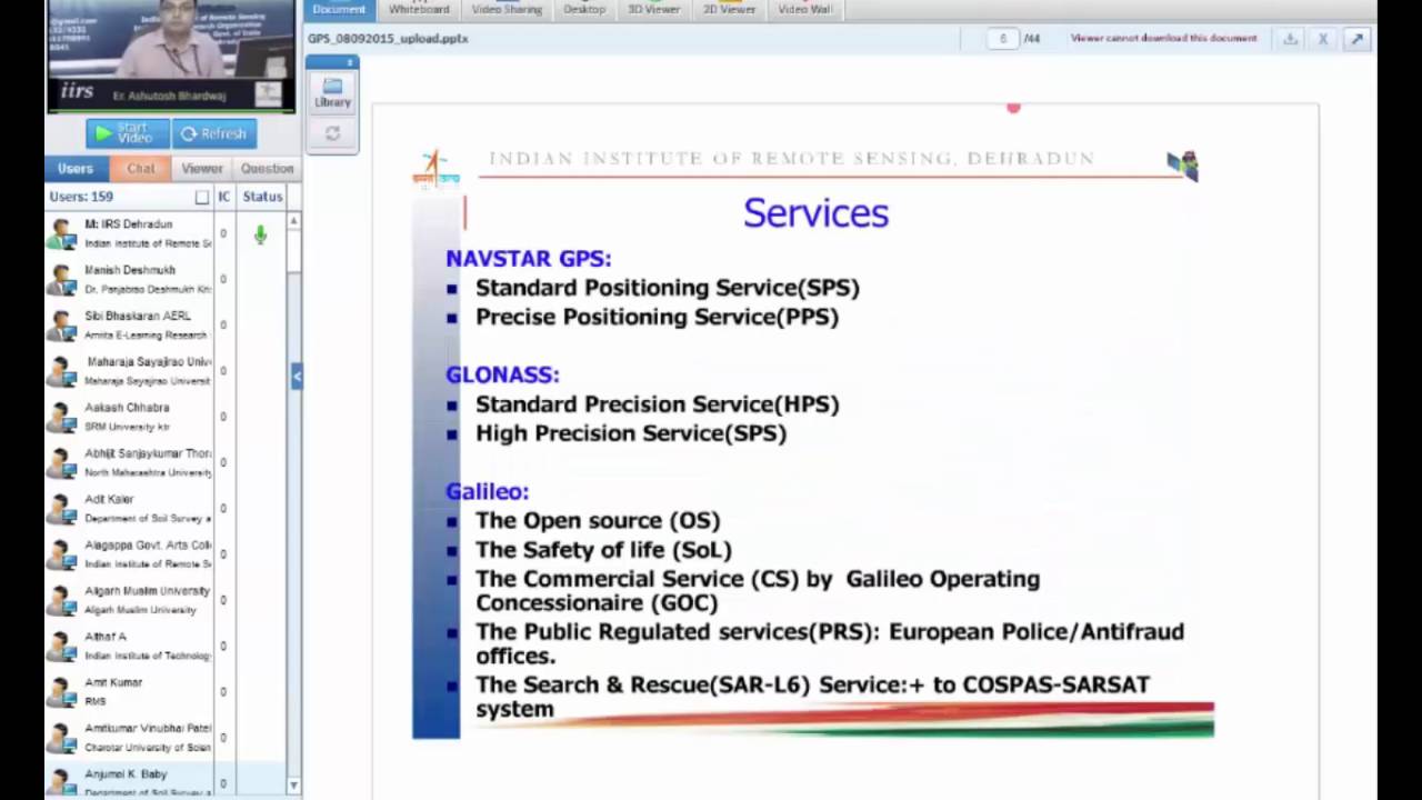
Differential GPS uses a minimum of two receivers: a base station at known coordinates and a rover station at unknown coordinates. The base station calculates errors in real-time by comparing known and calculated positions from broadcast ephemeris. These errors are applied to rover measurements. Baseline length affects observation time requirements, with longer baselines requiring more time to ensure four common satellites. The one-way ranging system calculates pseudo-range by multiplying signal travel time by light velocity. In differential GPS, the error is calculated as the difference between known and calculated positions. For example, if X, Y, Z is the known position and X', Y', Z' is the calculated position, the error is (X - X'), (Y - Y'), (Z - Z'). This error is applied to rover coordinates. The range between satellite and base station is known from ephemeris and reference coordinates. The difference between known and calculated ranges is translated into time corrections applied at the rover station. Two DGPS methods exist: post-processing (data downloaded and processed in office) and real-time (corrections transmitted via modem using RTCM format). Real-time kinematic (RTK) surveying provides immediate results for applications like aircraft landing.
Click to watch →
Lecture 28 : GPS errors and DGPS
18.9K
Differential GPS achieves centimeter-level accuracy through cooperative receiver operation. A stationary reference station at a known location calculates error differences between actual and computed satellite distances. These corrections are transmitted to a mobile rover, which applies them to its measurements. This approach eliminates common errors including satellite clock discrepancies, atmospheric delays, and orbital inaccuracies. The system requires at least four satellites for initial positioning, with the base station transmitting corrections to rovers within its communication range. This technology enables accuracies of 10-20 cm for moving applications and 1 cm or better for stationary surveys.
Click to watch →
Prerequisite Knowledge
- Concept 01Basic GNSS/GPS operational principles, specifically how trilateration and time-of-flight calculations are used to determine a receiver's position.
- Concept 02Common sources of satellite positioning errors, particularly how ionospheric and tropospheric atmospheric layers distort signal propagation.
- Concept 03The conceptual difference between code-phase measurements (standard GPS) and carrier-phase measurements (which track the actual signal wave).
- Concept 04The fundamental concept of Differential GPS (DGPS), where a stationary base station is used to calculate errors for a nearby mobile receiver.
Subsequent Learning
- Step 01Network RTK (NRTK) and Virtual Reference Station (VRS) technologies, which expand centimeter-level accuracy over wider regions using multiple base stations.
- Step 02Precise Point Positioning (PPP), a satellite-based alternative to RTK that provides decimeter-to-centimeter accuracy without requiring a local base station.
- Step 03Integration of RTK with Inertial Navigation Systems (INS/IMU) to maintain high-precision positioning during temporary satellite signal loss (GNSS dead reckoning).
- Step 04Practical applications of RTK in automated industries, such as autonomous farming, drone photogrammetry, and self-driving vehicle navigation.
RTK Basics
RTK Basics
0:02Playing Section
- 1
Defines RTK as real-time kinematic correction from base stations.
- 2
Improves GPS accuracy from meter to centimeter level.
- 3
Corrects atmospheric distortions affecting satellite signal timing.
Precise Point Positioning (PPP) and Sensor Fusion Alternatives
While Real-Time Kinematic (RTK) technology offers centimeter-level accuracy, it has significant limitations, notably its dependency on proximity to physical base stations (usually within 10–20 km) or stable communication links for correction data. This makes RTK costly and impractical in remote regions, marine environments, or areas with poor infrastructure. A major alternative is Precise Point Positioning (PPP), which delivers high-accuracy positioning globally using satellite orbit and clock corrections without requiring local base stations, though it typically suffers from longer convergence times. Furthermore, critics emphasize that RTK is highly vulnerable to signal blockages and multipath interference in 'urban canyons' or under dense canopy. In these scenarios, autonomous systems increasingly rely on Sensor Fusion—integrating GNSS with Inertial Navigation Systems (INS) and visual SLAM (Simultaneous Localization and Mapping). This approach provides robust, centimeter-level localization even when satellite signals are entirely obstructed, challenging the necessity of RTK-only solutions.
Deep Dive
Network RTK (NRTK) and Virtual Reference Station (VRS) technologies, which expand centimeter-level accuracy over wider regions using multiple base stations.

How Network RTK Works | NTRIP, VRS, CORS Explained
1.3K
Network RTK achieves centimeter-level accuracy by using a network of continuously operating reference stations (CORS) that broadcast correction data via NTRIP (Network Transport of RTCM via Internet Protocol) over the internet, eliminating the need for a local physical base station; this correction data is received by a single GNSS receiver like the Emlid Reach RX2, which uses either direct CORS mount point connections or virtual reference station (VRS) networks to calculate precise position corrections in real-time, with modern receivers also incorporating built-in IMUs for tilt compensation and enabling smartphone-based photogrammetry and LiDAR applications.
Click to watch →

Demystifying Network RTK: What Drives your Corrections Accuracy
133
This comprehensive section establishes the foundational concepts of Real-Time Kinematic (RTK) correction technologies for achieving centimeter-level GPS accuracy. Single baseline RTK uses a single fixed base station with a known position to correct rover observations by comparing raw GPS measurements, eliminating common errors like satellite orbit and clock biases. Network RTK extends this by using multiple distributed base stations with a central server that synthesizes virtual reference stations through geometric interpolation, extending effective correction range. VRS (Virtual Reference Station) is a delivery format where servers generate synthetic observations indistinguishable from single base stations, though they never match true single baseline performance. SSR (Satellite-Based Augmentation System) takes a physics-based approach by decomposing errors into orbits, clocks, ionosphere, troposphere, and receiver biases, allowing fewer stations to cover larger areas but requiring custom receiver software. The fundamental distinction lies in whether systems work directly with raw observables (OSR approaches) or model physical error sources, each with distinct trade-offs in coverage, complexity, and receiver compatibility.
Click to watch →

Webinar: GNSS Signal Processing and Navigation Techniques
973
Virtual Reference Station (VRS) extends RTK coverage by using a network of reference stations instead of a single station. The central processing facility computes atmospheric propagation errors from the network and generates virtual station data emulated at the user's approximate location. The user sends approximate coordinates via radio link, and the central facility returns corrected measurements simulating a nearby real reference station. This technique extends baseline limits to 100+ km while maintaining RTK-like performance. However, it requires two-way communication links and network density sufficient to cover the target area (approximately 5-10 stations for 10,000 km²).
Click to watch →
👨🏫 Curso ¡GRATIS! #02 - Levantamiento y Procesamiento de Puntos de Control con GPS Diferencial
5.7K
Advanced GNSS correction services include Satellite-Based Augmentation Systems (SBAS) providing internet-delivered corrections, Virtual Reference Station (VRS) creating synthetic nearby base stations, and network RTK using multiple reference stations. Single-baseline connects to specific stations; multi-baseline dynamically selects nearest stations. VRS virtually eliminates distance-related errors, achieving near-full receiver precision. These technologies represent the future of GNSS positioning, offering improved accuracy without local base station infrastructure, though they require compatible receivers and subscription services.
Click to watch →

GNSS測量ネットワーク型データサービス料金について 単点観測法の場合
554
Network RTK (Real-Time Kinematic) is a surveying technology that uses communication networks to provide real-time correction data. VRS (Virtual Reference Station) creates virtual reference stations at user-specified locations by interpolating data from nearby physical reference stations. This technology enables centimeter-level accuracy without establishing physical reference stations. The system requires communication with data service providers, which may involve subscription fees. Understanding these fundamentals is essential for surveyors considering network RTK for their work.
Click to watch →
Deep Dive
Precise Point Positioning (PPP), a satellite-based alternative to RTK that provides decimeter-to-centimeter accuracy without requiring a local base station.

GeoMax Webinar - Zenith40 and PPP
153
PPP (Precise Point Positioning) is a global satellite-based correction service that delivers centimeter-level positioning accuracy (2.5-3 cm horizontal, 5 cm vertical) directly to receivers via communication satellites, eliminating the need for local base stations; however, it requires a convergence time of approximately 15-18 minutes to achieve centimeter accuracy, and when combined with RTK networks, requires position adjustment calculations due to differences between global PPP reference frames and local network coordinate systems.
Click to watch →
RSGIS L22: DGPS, SBAS, RTK, PPS: How GPS Becomes More Accurate
261
PPP is an advanced GNSS technique using only a single receiver to achieve sub-meter level accuracy. It combines global GNSS satellite signals with correction data from a worldwide network of reference stations. PPP processes undifferenced measurements (raw observations without receiver-to-receiver differencing) and incorporates sophisticated modeling of error sources including atmospheric delays, ionospheric/tropospheric errors, satellite clock errors, and receiver biases. PPP requires a convergence period (estimating local errors) before achieving full accuracy. Advanced PPP can achieve 2.5 cm accuracy in 1 minute. Unlike RTK, PPP does not require a nearby base station.
Click to watch →

Practical Precise Point Positioning (PPP): Properties and Performance | Part 2: Q&A | Park & Weaver
316
Precise Point Positioning (PPP) achieves high-accuracy positioning through precise satellite orbit and clock corrections. Broadcast products offer 100 cm orbit accuracy and 1.5 m positioning error, while ultra-rapid products achieve 5 cm orbit precision with no latency. PPP differs from RTK in infrastructure requirements: conventional RTK needs direct reference station links, while PPP-RTK provides corrections as a space-based service. PPP-RTK offers broader coverage in remote areas lacking dense GNSS networks but typically achieves lower accuracy. OPUS uses differential processing requiring reference station visibility, while PPP uses standalone techniques constraining only satellite positions. PPP networks managed by analysis centers estimate parameters enabling standalone user solutions. Kinematic PPP requires convergence periods before achieving centimeter-level precision, unlike RTK's single-epoch capability. GPS-only solutions converge in ~1 hour, multi-system configurations reduce this to ~30 minutes, and multi-system integer ambiguity resolution further reduces it to ~15 minutes. PPP variants range from conventional PPP with float ambiguities to advanced PPP-RTK incorporating multi-system, multi-frequency, integer ambiguity resolution, and regional atmospheric constraints. The Galileo High Accuracy Service currently concentrates in Europe with planned global expansion. Dense regional reference networks enhance PPP-RTK performance by providing atmospheric constraints, demonstrating that PPP adoption complements rather than replaces existing infrastructure.
Click to watch →
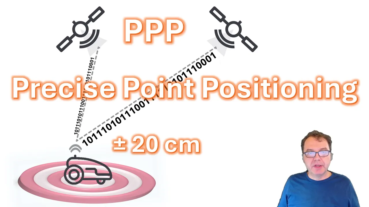
Precise Point Positioning (PPP) on Unicore GNSS Modules: Step-by-Step Setup
6.5K
Precise Point Positioning (PPP) is a GNSS navigation technique that achieves centimeter-level accuracy (approximately 20 cm) by combining satellite signal timing with additional correction data from global networks, eliminating the need for local base stations; to enable PPP on Unicore UM980/UM982 modules, users must first verify firmware version meets minimum requirements (11833+ for UM980, 11826+ for UM982), configure signal groups to include Galileo E6-HAS or BeiDou B2b-PPP services based on geographic location, set convergence parameters, and monitor solution quality through NMEA output where quality indicator '5' confirms PPP float solution has been achieved.
Click to watch →

Practical Precise Point Positioning (PPP): Properties and Performance |Part 1: Lectures| Park&Weaver
357
Precise Point Positioning (PPP) is a GNSS positioning technique that achieves centimeter-level accuracy using a single receiver by combining un-differenced carrier phase and code observations with precise satellite orbit and clock corrections from external sources such as the International GNSS Service (IGS). Unlike standard point positioning which relies solely on redundant observations to mitigate errors, PPP applies external corrections to model and eliminate systematic errors including ionospheric delay (corrected via dual-frequency combinations or external TEC products), tropospheric delay (separated into hydrostatic and wet components), tidal effects, relativistic effects, and antenna phase center variations. PPP offers advantages over relative positioning methods like RTK by eliminating the need for nearby reference stations, enabling global coverage without infrastructure limitations, though it requires an initial convergence period (typically 15-30 minutes) during which the carrier phase integer ambiguities are estimated before achieving high-precision solutions. Static PPP can achieve 2-6 mm horizontal and 4-6 mm vertical accuracy after convergence, while kinematic PPP provides approximately 1 cm horizontal accuracy in motion. Modern PPP services such as CSRS-PPP, Galileo High Accuracy Service, and PPP-RTK further enhance performance by providing real-time corrections and integrating atmospheric constraints.
Click to watch →
Deep Dive
Integration of RTK with Inertial Navigation Systems (INS/IMU) to maintain high-precision positioning during temporary satellite signal loss (GNSS dead reckoning).

Efisiensi Global Positioning System (GPS) - Real Time Kinematic (RTK) Untuk Kegiatan Konstruksi
109
IMU (Inertial Measurement Unit) integrates with RTK to provide enhanced positioning capabilities. IMU contains accelerometers, gyroscopes, and magnetometers that measure acceleration, rotation, and magnetic fields. This integration allows accurate positioning even when GPS signals are degraded or unavailable. The combination is particularly valuable for autonomous equipment navigation, drone mapping, and surveying in challenging environments where GPS signals are obstructed.
Click to watch →

Inside GNSS Webinar Case Studies in GNSS INS Integration 12 15 15 Recording
130
Three integration modes exist: loose integration (solution-level fusion, fails without GNSS fixes), tight integration (navigation measurement fusion even during outages), and deep integration (signal processing level, accumulating signals for 1 second vs. 20ms). For automotive applications, loose integration is inadequate. Deep integration accumulates signals for longer periods, enabling recovery of weak/attenuated signals. Inertial estimates help adjust replica signals for dynamic changes, preventing energy loss.
Click to watch →
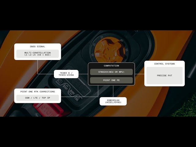
Getting it Right - Precise Navigation for Lawn and Turf
215
Uncorrected GNSS achieves only 1-2 meter accuracy due to clock errors, orbital errors, atmospheric delays, multipath effects, and signal occlusion. RTK solves these by using base stations with known positions to provide real-time corrections. Modern receivers track multiple constellations (GPS, GLONASS, BeiDou, Galileo) and multiple frequency bands (L1, L2, L5, B2B, B3i, E6) to improve signal availability and anti-jamming capability. When GNSS is unavailable, sensor fusion incorporating IMUs, wheel sensors, cameras, and LIDAR maintains continuous positioning through dead reckoning until signals return.
Click to watch →

Dev Kit Weekly: ACEINNA OpenRTK330LI Evaluation Kit
465
The OpenRTK330LI is a high-performance GNSS receiver that integrates three redundant six-axis inertial measurement unit (IMU) sensors with a Teseo V chipset, enabling centimeter-level dead reckoning accuracy for precision navigation applications such as autonomous vehicles, ADAS systems, agricultural vehicles, and commercial drones. The system supports multi-constellation GNSS (GPS, GLONASS, BeiDou, Galileo, QZSS, SBAS) with RTK accuracy down to 0.02 meters horizontally and 0.03 meters vertically, while also providing velocity measurements accurate to 0.01 m/s horizontally and 0.02 m/s vertically, heading accuracy within 0.5 degrees, and altitude accuracy within 0.1 meters. The platform features an open-source software stack with GNSS RTK/PPP correction engine, sensor fusion algorithms, and connectivity options including Ethernet, CAN, UART, SPI, and Bluetooth.
Click to watch →
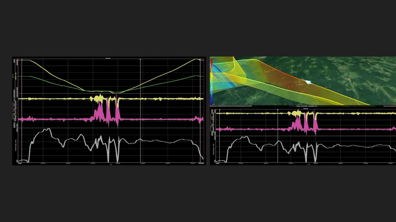
Dewesoft Inertial Navigation Systems (GPS/GNSS and IMU/INS)
2.4K
Modern navigation systems combine GPS/GNSS receivers with Inertial Measurement Units (IMUs) containing accelerometers and gyroscopes to achieve accurate positioning; GPS provides long-term position tracking while IMUs maintain short-term stability and accuracy in areas with poor or no satellite signal, such as urban canyons, tunnels, and forests, with advanced systems achieving centimeter-level accuracy through Real-Time Kinematics (RTK) corrections and sensor fusion algorithms.
Click to watch →
Deep Dive
Practical applications of RTK in automated industries, such as autonomous farming, drone photogrammetry, and self-driving vehicle navigation.

Will This Track Survive It’s Last Job!?
196.2K
RTK (Real-Time Kinematic) GPS technology enables precise mapping of agricultural field lines. The farmer uses an RTK globe mounted on the tractor to map tile lines, drive on top of them, close trenches, and level the ground. This technology allows farmers to locate tile lines within 5 feet accuracy, making future maintenance and modifications much easier. The farmer explains that since adopting RTK and precision tiling, adding new tile lines has become very simple - farmers can walk to their phone, draw on their operation center, and locate lines within 5 feet.
Click to watch →

con el PILOTO AUTOMATICO ahora es más fácil cosechar fjdynamic
21.1K
RTK GPS guidance systems enable automated steering for agricultural machinery by using a stationary base station antenna that provides centimeter-level accuracy, allowing tractors to follow precise straight lines during planting, spraying, and harvesting operations with minimal overlap or missed areas.
Click to watch →
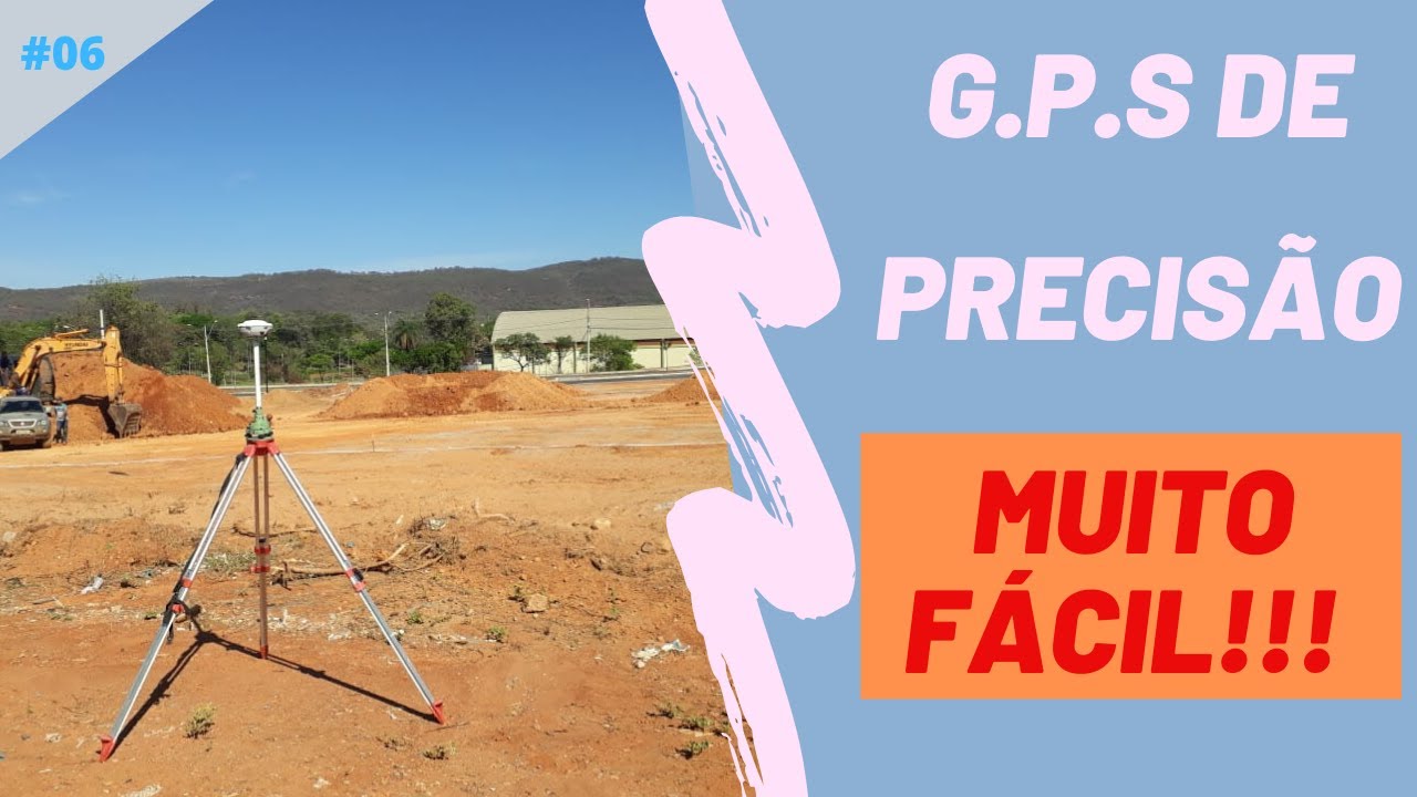
Tudo que Precisa saber para operar um GPS de Precisão RTK - Simples, Rápido e Prático
58.5K
GPS RTK (Real-Time Kinematic) technology enables millimeter-precision surveying by using a base station and rover device that communicate via radio to correct satellite positioning errors; the system requires proper setup including base station configuration with known coordinates, rover connection via Bluetooth, and understanding of key parameters like frequency (typically 6 MHz) and elevation angle (typically 10 degrees), with accuracy ranging from 2-3mm in fixed mode to 10-12mm when searching for satellites.
Click to watch →

RTK GPS/GNSS with Base and Rover
195.2K
RTK (Real-Time Kinematic) GPS/GNSS achieves high-accuracy positioning by using two receivers: a stationary base station at a known coordinate that observes satellites and broadcasts corrections, and a mobile rover that receives these corrections in real-time to determine its precise location relative to the base, enabling survey-grade accuracy of approximately 1 centimeter plus 2 parts per million.
Click to watch →
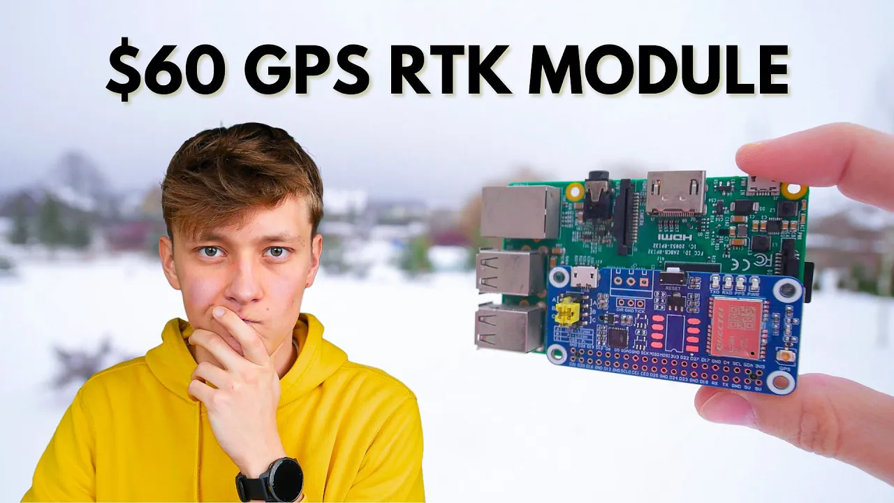
This $60 GPS RTK Module Claims Centimeter-Level Positioning.
117.4K
GPS RTK (Real-Time Kinematics) is a satellite positioning technology that achieves centimeter-level accuracy by using a base station with a known precise location to calculate and correct positioning errors for a rover unit, making it significantly more accurate than standard GPS systems which only achieve meter-level precision; this technology can be implemented cost-effectively using affordable $60 modules that connect directly to a Raspberry Pi, with open-source networks of base stations available in many countries to eliminate the need for expensive proprietary infrastructure.
Click to watch →
RTK Basics
RTK Basics
0:02- 1
Defines RTK as real-time kinematic correction from base stations.
- 2
Improves GPS accuracy from meter to centimeter level.
- 3
Corrects atmospheric distortions affecting satellite signal timing.
Precise Point Positioning (PPP) and Sensor Fusion Alternatives
While Real-Time Kinematic (RTK) technology offers centimeter-level accuracy, it has significant limitations, notably its dependency on proximity to physical base stations (usually within 10–20 km) or stable communication links for correction data. This makes RTK costly and impractical in remote regions, marine environments, or areas with poor infrastructure. A major alternative is Precise Point Positioning (PPP), which delivers high-accuracy positioning globally using satellite orbit and clock corrections without requiring local base stations, though it typically suffers from longer convergence times. Furthermore, critics emphasize that RTK is highly vulnerable to signal blockages and multipath interference in 'urban canyons' or under dense canopy. In these scenarios, autonomous systems increasingly rely on Sensor Fusion—integrating GNSS with Inertial Navigation Systems (INS) and visual SLAM (Simultaneous Localization and Mapping). This approach provides robust, centimeter-level localization even when satellite signals are entirely obstructed, challenging the necessity of RTK-only solutions.
Basic GNSS/GPS operational principles, specifically how trilateration and time-of-flight calculations are used to determine a receiver's position.
Common sources of satellite positioning errors, particularly how ionospheric and tropospheric atmospheric layers distort signal propagation.
The conceptual difference between code-phase measurements (standard GPS) and carrier-phase measurements (which track the actual signal wave).
The fundamental concept of Differential GPS (DGPS), where a stationary base station is used to calculate errors for a nearby mobile receiver.
Network RTK (NRTK) and Virtual Reference Station (VRS) technologies, which expand centimeter-level accuracy over wider regions using multiple base stations.
Precise Point Positioning (PPP), a satellite-based alternative to RTK that provides decimeter-to-centimeter accuracy without requiring a local base station.
Integration of RTK with Inertial Navigation Systems (INS/IMU) to maintain high-precision positioning during temporary satellite signal loss (GNSS dead reckoning).
Practical applications of RTK in automated industries, such as autonomous farming, drone photogrammetry, and self-driving vehicle navigation.
9K views75likes2:09@InertialsenseOriginal Release: 2021-05-07
[Music] [Music] so rtk stands for real-time kinematic what it means is it's taking a correction service from a surveyed gps base station applying that correction to the the rover or the moving gps system it's able to correct for atmospheric distortions and errors in the in the existing gps system which is what brings it down from meter level accuracy to centimeter level accuracy and positioning because the gps system is triangulating itself off of these gps signals from moving satellites in in free space the satellite signal is traveling through great distances of atmosphere and those distances of atmosphere affect the the speed at which the signal arrives at the gps receiver the position estimate is is critical to the timing of those signals but because the atmosphere changes and the time of arrival changes on on each of those signals based on weather conditions time of day there's there's a lot of factors then the actual position estimate will vary there's error as a result it's kind of like having a a fuzzy tape measure where your your mark isn't isn't very clear and it's just simply you can't read it there's also air in the in the gps signals themselves so what rtk does is it takes a correction from a surveyed known location that is in relatively close proximity to the to the rover which can be up to 20 miles and it applies that correction to account for these atmospheric distortions and errors [Music] foreign
Up Next

19:55
iNav Flight Controller Introduction: GPS Flight Modes Explained
@Painless360
110.5K views•2017-01-20

12:54
Triumph of Orthodoxy Icon: Byzantine Art & History Explained
@BenCallan
2.1K views•2024-08-06

9:49
FastAPI vs Flask vs Django: Choosing the Right Python Web Framework
@TechWithTim
302.5K views•2024-05-26

1:42
Game of Thrones Opening Credits: A Cinematic Analysis
@gameofthrones
46.3M views•2011-04-18
Related Study Plans & Knowledge Roadmaps
Structured learning paths in General & Interdisciplinary Studies
general-studies
Elevator Engineering: History, Physics & Cities
01From Hoists to Safety Brakes: The Dawn of Vertical Lift
02Hydraulic vs. Traction: The Engineering Physics of Elevators
03Modern Speed, Safety, and Algorithms
+ 2 more learning modules
12h5 modules
Explore Roadmap
general-studies
Rubber: Material Science, History & Geopolitics
01Origins of Natural Rubber & Mesoamerican History
02The Chemistry of Natural Rubber & Vulcanization
03The Geopolitics of the Rubber Boom & Colonization
+ 2 more learning modules
12h5 modules
Explore Roadmap
general-studies
Containerization: Evolution, Logistics & Trade
01Ancient Trade & Bulk Cargo: Amphorae to Barrels
02The Industrial Revolution & Cardboard Packaging
03The Containerization Revolution: Malcom McLean
+ 2 more learning modules
12h5 modules
Explore Roadmap
general-studies
Textile Tech: Evolution, Labor & Global Impact
01Pre-Industrial Textiles: Handloom & Cottage Industry
02Mechanization: The Spinning Jenny to the Power Loom
03The Factory System & Global Labor Transformation
+ 2 more learning modules
10h5 modules
Explore Roadmap