















![[Curso de Verão 2023] OF4 Detectores de partículas no LHC - 2/5](https://i.ytimg.com/vi/Q7R2aUMIFEY/maxresdefault.jpg)

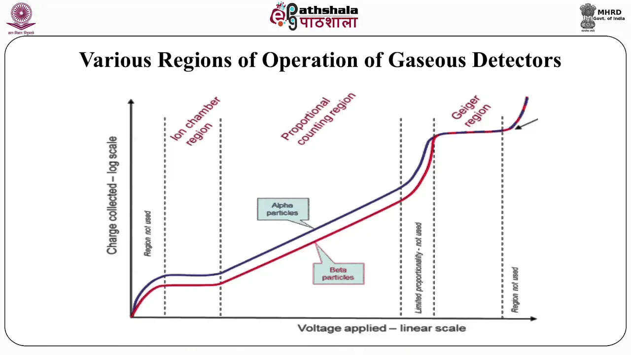




Gas-filled radiation detectors operate through five distinct voltage regions: (1) Recombination region where ion-electron pairs recombine without detection; (2) Ion chamber region where pulses are proportional to primary ionization charge; (3) Proportional region where gas amplification begins but maintains approximate proportionality; (4) Limited proportionality region where secondary ionizations swamp primary signals; and (5) Geiger-Mueller region where all primary ionization information is lost due to massive gas amplification, producing uniform large pulses regardless of initial charge deposition.
Radiation Detection: Gas Amplification and Ionization Chambers
Added:Fundamentals of ionizing radiation, including the distinctions between alpha, beta, and gamma radiation.
The concept of atomic ionization, specifically how incoming radiation strips electrons from gas atoms to create electron-ion pairs.
Basic electromagnetism, particularly how electric fields exert forces on charged particles (electrons and ions) to induce current.
The relationship between voltage, electric field strength, and the drift velocity of free charges in a medium.
The detailed design and chemistry of Geiger-Mueller counters, including the critical role of quenching gases to stop continuous discharge.
Signal processing electronics for radiation detection, such as pre-amplifiers, pulse-shaping circuits, and multi-channel analyzers.
Alternative radiation detection technologies, specifically solid-state semiconductor detectors and scintillation counters.
Practical calibration techniques and radiation protection protocols using gas-filled survey meters in clinical or industrial settings.
12.5K views134likes4:38Original Release: 2017-09-27
Now let’s go look at the construction details of gas-filled detectors.
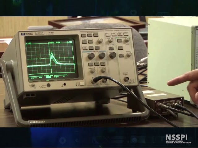
Usually these detectors are cylinders with an anode wire along the center line of the detector.
The electrons are collected by the anode, and the large gas ions migrate to the walls of the detector, the cathode, and are neutralized there by the electrons returning back through the electronics.
If the voltage between the anode and the cathode is sufficiently high, then recombination is stopped, and the electrons drift towards the anode wire, having multiple collisions with gas molecules in the detector.
These electrons reach the anode wire, not all at the same time, but over the course of a few milliseconds because of the random nature of how often they collided with gas molecules, how much energy was taken away during the collisions, where in the sensitive volume each electron was created, and other factors.
With the voltage set only to stop recombinations, the electrons collected are those created directly by the interaction of the ionizing radiation with the detector, or primary ionization.
If we raise the voltage difference between the anode and the cathode, something interesting begins to happen.
An electron, after being stopped by a collision with a gas molecule, can gain enough energy from the electric field between hits to cause an ionization the next time it hits a gas molecule, creating secondary ionization.
This multiplication of electrons by secondary ionization is called gas amplification.
The primary and secondary ionization are generally indistinguishable, and what comes from the detector is just a larger pulse.
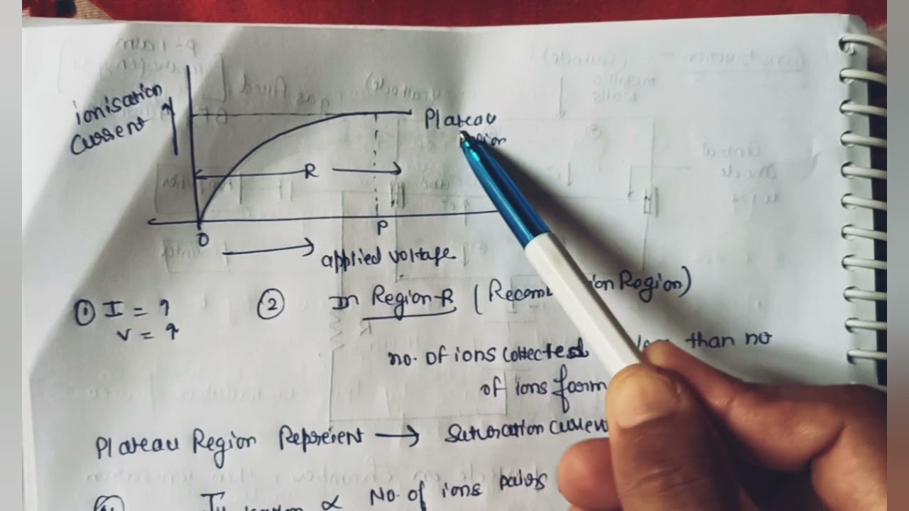
This graph shows what happens to the detector signal as the voltage difference between the anode and cathode is increased.
With no, or very low, voltage, the ion electron pair will simply recombine, and because scientists are such dull and boring folks, this is called the recombination region.
When enough voltage is applied to stop recombination, but is not high enough to cause gas amplification, the detector is in the ion chamber region, region two here on this graph.
The two lines here represent the size of the pulse coming from the detector.
The lower line is set at some arbitrary amount of charge, and the higher line is for double that amount of charge in the detector.
As we can see, the pulses in the ion chamber region are proportional to the amount of charge deposited in the detector’s sensitive volume.
As the voltage is increased, gas amplification starts, first, rarely, because only a few of the electrons will escape gas collisions long enough to gain the energy they need to cause secondary ionization.
But, finally at the end of the region three, the proportional region on this graph, a significant fraction of the electrons do.
Next is out region four, the region of limited proportionality, where the height of the pulse does not necessarily correspond to the number of primary ionizations, because the secondary ionizations are beginning to swamp the original primary ionization signal.
Region five is the Geiger-Mueller region, and in this region, all of the information from the primary ionizations is lost.
Whether one electron or billions of electrons were created by a primary ionization, the gas amplification is so large that the primary signal is insignificant.
Above this is the region called, “Burning your anode wire if you do.” This should be avoided if you want to keep your detector working.
Up Next
12:35
How Scintillation Counters Work: PMT & Electron Multiplication Explained
@PhysWhiz
56.9K views•2016-09-12

12:53
21cm Hyperfine Transition in Neutral Hydrogen: Radio Astronomy Basics
@AaronRobertParsons
12.4K views•2011-10-13

3:53
Semiconductor Detectors Explained: Energy Bands & Physics
@nuclearsecuritynsspi
60.5K views•2010-12-02

27:14
Entropy and the Second Law of Thermodynamics Explained
@veritasium
27.5M views•2023-07-01
Related Study Plans & Knowledge Roadmaps
Structured learning paths in Physics
physics
Nuclear Physics (Decay, Fission & Reactors)
01Atomic Structure and the Binding Force
02Radioactive Decay and Half-Life
03Nuclear Fission Mechanics and Chain Reactions
+ 2 more learning modules
12h5 modules
Explore Roadmap
physics
Soft Matter (Polymers, Colloids & Rheology)
01Foundations of Soft Matter & Thermal Forces
02Polymer Physics and Macromolecules
03Colloids, Surfactants, and Self-Assembly
+ 2 more learning modules
38h5 modules
Explore Roadmap
physics
Analytical Mechanics: Lagrangian & Hamiltonian
01Mathematical Foundations: Calculus of Variations
02From Newtonian Mechanics to Constraint Dynamics
03The Principle of Least Action & Lagrangian Mechanics
+ 3 more learning modules
28h6 modules
Explore Roadmap
physics
General Relativity (Spacetime & Cosmology)
01Foundations of Relativity: Special Relativity
02The Geometry of Spacetime: Equivalence Principle & Curvature
03Einstein's Field Equations: The Mathematics of Gravity
+ 2 more learning modules
55h5 modules
Explore Roadmap