





















Propellers generate thrust by acting as rotating airfoils that create pressure differentials, accelerating air rearward and producing forward thrust through Newton's third law; their efficiency depends on accelerating large masses of air at low velocities rather than small masses at high velocities, which is why they feature large diameters and twisted blades designed to maintain optimal angle of attack across the span, though they face fundamental speed limits when blade tips approach the speed of sound (around Mach 0.85-0.9), constraining maximum aircraft speed to approximately Mach 0.6-0.7.
Propeller Physics: Aerodynamics, Design, and Efficiency Explained
Added:Basic fluid mechanics, including Bernoulli's principle and the generation of lift and drag on an airfoil.
Newton's laws of motion, particularly the conservation of momentum and action-reaction forces.
Rotational dynamics, specifically the relationship between angular velocity, linear velocity at a radius, and torque.
The concept of control volumes and mass flow rate in fluid dynamics.
Blade Element Momentum (BEM) Theory, combining 2D airfoil theory with 1D momentum theory for detailed aerodynamic analysis.
The mechanics and control systems of variable-pitch and constant-speed propellers in practical aviation.
Computational Fluid Dynamics (CFD) methods for simulating propeller wake interactions, hub losses, and tip vortices.
Advanced propulsion configurations, such as contra-rotating propellers, ducted fans, and open rotor designs.
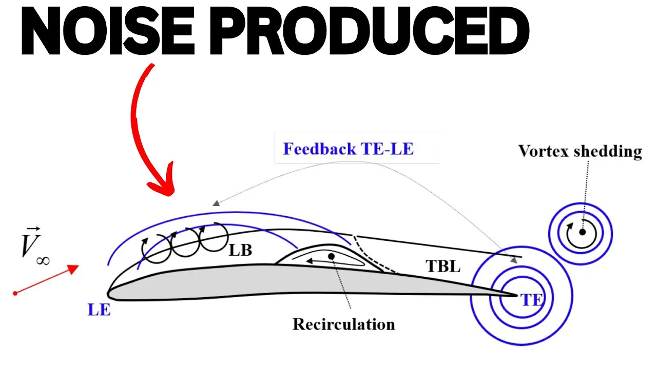
Propeller aeroacoustics, focusing on noise generation mechanisms and acoustic reduction techniques.
222 views9likes16:51Original Release: 2025-12-18
Propellers are making a comeback. As aviation electrifies, they're returning to center stage because they're remarkably efficient, converting 85% of shaft power into thrust. But to understand why they work so well, and why we'll see them powering the next generation of aircraft, we need to understand the physics. How does a spinning blade actually create thrust?
Why are they twisted? What determines how much thrust you get? And critically, what are the fundamental limits that forced aviation toward jets for high-speed flight? The complete propulsion system has two components.
The power plant generating mechanical energy and the propeller converting that power to thrust. Today, we're focusing entirely on the propeller. How it works, why it's designed the way it is, and what limits its capabilities. Let's start with the fundamental question. How does a propeller create thrust?
At its core, a propeller is really just a rotating wing, or rather wings. Each propeller blade is an air foil, very similar to an aircraft wing. In fact, lift and thrust are generated by almost the same physics. As the propeller spins, the air foils create a pressure differential. Lower pressure in front of the blade and higher pressure behind it.
The high pressure air has increased energy and accelerates rearward, trading pressure for velocity, equalizing the pressure to the ambient. By Newton's third law, this acceleration of the air rearwards results in an equal and opposite force, thrust. The propeller basically grabs the air and throws it backward. If we could visualize the air flow, we'd see the air velocity gradually increases as it approaches the propeller, jumps significantly across the blades themselves, then continues accelerating behind the propeller before tapering off. This accelerated column of air, the slipstream, represents the momentum change that creates thrust. The propeller's job is momentum transfer.
The more air mass you accelerate, and the faster you accelerate it, the more thrust you produce. To understand propeller performance, engineers begin with momentum theory, also known as actuator disc theory. This treats the propeller as an infinitely thin disc that creates a pressure jump, accelerating the air that passes through it. Real propellers have blades, tips, roots, all sorts of complexity. But this simplified model gives us incredibly valuable insights, and it's the foundation for everything else. By applying conservation of momentum to the air passing through the disc, we get a nice simple thrust equation. Thrust equals the mass flow rate time the change in velocity where v kn is the free stream velocity and v is the exit velocity in the wake. So for a given propeller and flight condition, thrust depends entirely on how much we increase the exit velocity. Want more thrust?
Accelerate more air. But how that air is accelerated is the key to propulsive efficiency.
This is the equation. Efficiency is 2 over 1 plus the exit velocity over the free stream velocity.
If exit velocity equals free stream velocity, we'd have 100% efficiency, but zero thrust because we haven't actually accelerated anything. For thrust, we needed that exit velocity greater than the free stream velocity. But the larger this ratio, the lower our efficiency.
For a given thrust, you can either accelerate a small mass of air by a large velocity change or a large mass of air by a small velocity change. This equation tells us it's more efficient to accelerate a large mass of air by a small amount than a small mass by a large amount. This is why propellers have large diameters. They're designed for low specific thrust, moving lots of air slowly to maximize efficiency.
So, we've established that propellers create thrust by accelerating air and that efficiency depends on the velocity ratio. But how do we characterize the actual operating condition of a propeller? We need a different way to compare different flight scenarios, takeoff versus cruise, different aircraft speeds, different propeller sizes. Engineers use a dimensionless parameter called advance ratio denoted by J where V is the flight velocity, N is the rotation speed in revolutions per second and D is diameter. This captures the fundamental relationship between how fast you're flying and how fast the propeller is turning relative to its size. It's essentially comparing the distance the aircraft travels per revolution to the propeller diameter. If you look at a typical propeller efficiency curve plotted against advanced ratio, you'll see efficiency rises, peaks somewhere around J= 1 to 1 1/2, depending on the design, then drops off sharply at higher values.
For low J's, like takeoff, when you're moving slowly but the propeller is spinning fast, you get high thrust but lower efficiency. At high j like cruise flight at high speed gives lower thrust but much better efficiency.
Advance ratio is the key parameter for understanding propeller operation. But these parameters are driven by another part of the blad's geometry. Its pitch.
Geometric pitch is a design parameter chosen when the propeller is manufactured. It determines how aggressively the blade is angled. Higher pitch means steeper blade angles trying to move more air per revolution.
When propellers were introduced, you had to choose the pitch for your primary mission. A climb prop has lower pitch optimized for takeoff and climb performance, while a cruise prop has higher pitch, optimized for high speed efficiency. You're essentially choosing which point on the J curve you want to operate at for your typical flight condition. I'm sure you've noticed the problem with these fixed pitch propellers. you can only be optimal at one advance ratio. The solution was the constant speed propeller, which automatically adjusts blade angle to maintain optimal RPM as flight conditions change. The pilot sets a target RPM with the propeller control. A governor system, which is typically hydraulic or electric, continuously measures the actual RPM and adjust the blade angle to match the target. During takeoff at low speed, the system commands low blade angles for high thrust. As you accelerate and climb, the blades automatically rotate to steeper angles to maintain that target RPM, keeping you near peak efficiency on the J curve. You can think of this similar to changing gears. This is why most high performance aircraft have constant speed props. They operate across a wide range of speeds and need to maintain efficiency throughout the flight envelope.
But as with everything, there are trade-offs. Small aircraft like drones usually have constant pitch propellers because the weight and complexity just aren't worth it.
Now that we understand the operating parameters, let's see how we characterize and predict thrust performance. Here's the equation for thrust, where CT is the thrust coefficient, row is air density, N is the rotation speed, and D is the diameter. Thrust scales with rotation speed squared and diameter to the 4th.
Double the diameter and all else equal, you get 16 times more thrust potential.
This is why diameter is such a critical design choice. It's not just about efficiency. But just as wings have a lift coefficient, propellers have a dimensionless thrust coefficient that lets us compare different designs across size and operating conditions. It allows us to have a single number which tells us how effectively the propeller converts rotation into thrust.
We can rearrange the thrust equation to define the thrust coefficient. By pulling out all the size, speed, and density effects of thrust, we get the dimensionless number that characterizes the propeller's aerodynamic design. A small propeller at high RPM and a large propeller at low RPM can have the same thrust coefficient if they have the same geometry and operate at the same advanced ratio. Most propeller manufacturers publish charts showing CT versus J for their designs. These charts let you verify that a particular propeller will work for your aircraft by checking whether it produces enough thrust at your cruise condition while operating at good efficiency.
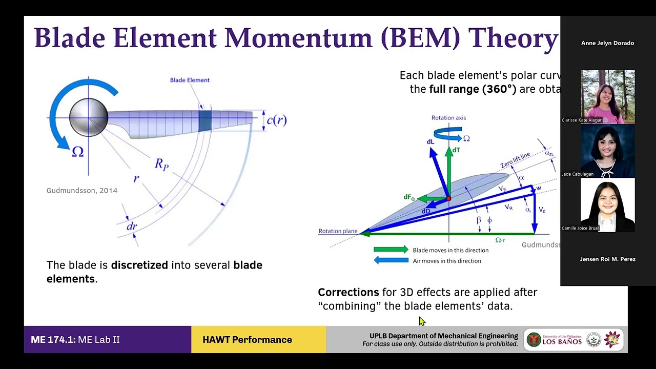
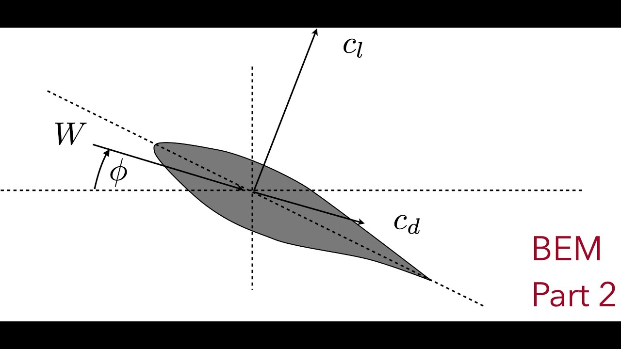
Thrust coefficient typically decreases as J increases. Maximum thrust at low J during takeoff, lower thrust at high J in cruise. With this understanding of how we characterize propeller performance, let's zoom in and see exactly how the propeller blade actually works. We need to look at what's happening along the span. Because air flow and the blades themselves are not the same from root to tip. This is called blade element theory. Imagine dividing the propeller blade into thin sections at different radi. Each section experiences two velocity components. The first is rotational velocity which increases linearly with the radius. The tip moves much faster than the route.
Second is forward velocity, the aircraft's speed, which is the same for all sections. These combine to create the relative wind that each blade section actually sees. Here's the key though. Near the hub, where rotational velocity is low, the relative wind comes almost straight ahead. Out at the tip, where rotational velocity is very high, the relative wind comes from an angle much more aligned with the rotation plane. To maintain an optimal angle of attack across all sections, which is typically 4 to 8°, we must change the blade's geometric angle along the span.
This is why propellers are twisted. An untwisted blade would be a disaster. The root sections would stall from excessive angle of attack while the tip sections would produce almost no thrust. The twist ensures every section operates efficiently. This blade element framework is one of the main ways engineers actually design propellers and calculate those thrust coefficient curves we discussed earlier by analyzing each section's contribution and integrating along the span. As you can imagine, this gets complicated quickly when considering the inflow of air and bending of blades under stress and more.
But hopefully this helps you understand the general concept. Now, let's look at how designers apply these principles to create real efficient propellers. But before we continue into design considerations and limitations, I'm curious, what brought you to this video?
Are you working on a project, studying for a class, or just genuinely curious how these things work? Let me know in the comments. And if you've made it this far, consider liking and subscribing.
With a small channel, every last person makes a huge difference. Now, let's explore how designers translate theory into hardware and what real world constraints they face. As with everything in engineering, every propeller is a carefully balanced set of compromises. The twist isn't just linear from root to tip. Designers commonly use blade element theory to optimize the distribution for specific operating conditions with the goal to have each section operating near its optimal angle of attack at cruise speed where aircraft typically spend most of their time. But propellers need to operate across a range of speeds from takeoff to landing.
So most propellers must make compromises. Twist is not the only thing that varies across the span. Blades are typically wider near the root and narrower toward the tip. The root must carry the centrifugal force of the entire outer blade and resist bending moments from thrust. So it needs more structural depth. The tapering toward the tip means less of the thrust is generated there lowering the bending moment. Remember from earlier if you want more thrust increase diameter thrust scales with d 4th. So this is powerful. More swept area means more mass flow which means you got it better efficiency. But unfortunately, we have to live in the real world with constraints. First, structural constraints. Longer blades mean higher centrifugal forces and bending moments. Second, ground clearance on takeoff becomes an issue.
Third, and most critically, tip speed.
Tip speed is the limiting factor for high-speed flight. This is why high-speed props must be smaller than you'd think. Instead of increasing diameter, you can increase the number of blades. Why? More blades mean more blade area working on the air per revolution, moving more air. But there are diminishing returns. Each blade operates in the disturbed flow from the blade ahead of it. This interference reduces blade efficiency per blade.
Different sections of the blade use different air foils. Near the route, where flow speeds are lower and angles of attack higher, designers use thicker air foils optimized for good low- speed performance and good stall characteristics. Near the tip, flow speeds are higher, so thinner sections are used, which handle high speeds better. The blade tips are where some of the worst losses occur. Air spills around the tip from high to low pressure, creating strong vortices.
These are energy that doesn't contribute to thrust.
Modern designs use elliptical tips, sweat tips, or even small winglets to minimize these losses. Specialized tip shapes can recover 2 to 3%, which may not sound like much, but is massive.
A well-designed modern propeller achieves 85 to 90% efficiency rather than the theoretical 95% plus. And that's a remarkable achievement given all of these competing constraints. But there's one constraint we haven't discussed yet that fundamentally limits what propellers can do. The speed of sound. Each point on the blade moves at a velocity combining the aircraft's forward speed and the rotational velocity at that radius. As blade tips approach the speed of sound, shock waves form on the blade surfaces, causing a massive drag increase and thrust reduction leading to efficiency collapse and an intense noise which is essentially a continuous sonic boom. The practical limit is around Mach.85 to.9 for blade tips. But because the blades are moving relative to the aircraft, that means the aircraft's speed is limited even more. If you're cruising at Mach 6, your tip speed is probably close to Mach.8. You have very little margin.
This constrains maximum aircraft speed to around Mach. 6 to 7 before efficiency collapses. And there isn't really a way around this. It's a fundamental barrier.
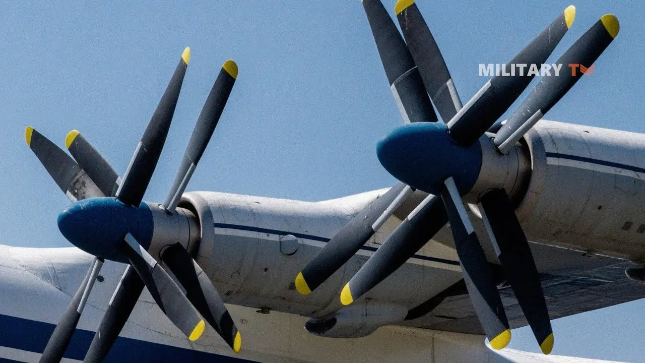
The Russians ran up against it in the 50s with the Tupalev TU95 employing contraotating propellers to achieve Mach 73, which is about as fast as you can practically go. The TU95 uses swept blades and careful design to operate near this limit, but it's incredibly loud and mechanically complex.
The US did try to push through this barrier. Meet the XF84H, also known as Thunder Screech, an experimental aircraft from the 1950s with supersonic tip propellers. It produced a continuous sonic boom audible for miles that could be heard indoors through closed windows. Personnel reported nausea, headaches, and seizures. It was the loudest aircraft ever built and a complete failure as a practical machine.
More modern prop fan designs with thin swept blades, more like fan blades on a jet engine, can push to mock 75 to8.
Sweep helps delay shock formation like swept wings on a high-speed aircraft.
They also employ many blades 8 to 12 or more to maintain thrust at smaller diameters. But beyond this, the physics just work against you. You can't just brute force past the sound barrier with propellers. That's why jet engines were developed and why they dominate high-speed aviation today. Propellers will always have their place in aerospace due to their efficiency in converting rotation to thrust. And as electric aircraft become more prevalent, more research has continued to go into their design. I hope this deeper dive into propellers gave you a clearer picture of their engineering trade-offs, but I want to be clear that there is so much more than I can cover in just one video. But for now, I'll leave it here.
Thanks for watching and I'll see you in the next
Up Next
70:33
Fluid Mechanics: Shock Waves & Compressible Flow (29 of 34)
@CPPMechEngTutorials
70.9K views•2018-08-11

12:53
21cm Hyperfine Transition in Neutral Hydrogen: Radio Astronomy Basics
@AaronRobertParsons
12.4K views•2011-10-13

32:32
NMR Spin Physics I: Zeeman Effect, Resonance Condition & Larmor Frequency
@nptel-indianinstituteofsci8064
2.3K views•2024-01-17

27:14
Entropy and the Second Law of Thermodynamics Explained
@veritasium
27.5M views•2023-07-01
Related Study Plans & Knowledge Roadmaps
Structured learning paths in Physics
physics
Nuclear Physics (Decay, Fission & Reactors)
01Atomic Structure and the Binding Force
02Radioactive Decay and Half-Life
03Nuclear Fission Mechanics and Chain Reactions
+ 2 more learning modules
12h5 modules
Explore Roadmap
physics
Soft Matter (Polymers, Colloids & Rheology)
01Foundations of Soft Matter & Thermal Forces
02Polymer Physics and Macromolecules
03Colloids, Surfactants, and Self-Assembly
+ 2 more learning modules
38h5 modules
Explore Roadmap
physics
Analytical Mechanics: Lagrangian & Hamiltonian
01Mathematical Foundations: Calculus of Variations
02From Newtonian Mechanics to Constraint Dynamics
03The Principle of Least Action & Lagrangian Mechanics
+ 3 more learning modules
28h6 modules
Explore Roadmap
physics
General Relativity (Spacetime & Cosmology)
01Foundations of Relativity: Special Relativity
02The Geometry of Spacetime: Equivalence Principle & Curvature
03Einstein's Field Equations: The Mathematics of Gravity
+ 2 more learning modules
55h5 modules
Explore Roadmap