Bernoulli's principle states that as the velocity of a fluid increases, its pressure decreases; this can be demonstrated using a Venturi tube where air flows faster through the narrow section, creating lower pressure that causes colored water in a U-shaped tube to rise in the middle section.
Bernoulli's Principle Demo: Venturi Tube Physics Experiment
Added:Deep Dive
The concept of fluid pressure, including how fluids (liquids and gases) exert force over a given area.

GRAVITATION class 9 | Thrust and Pressure, Pressure in fluid | Buoyant force | RC Sir
119
Pressure in fluids (liquids and gases) is created by the continuous collision of fluid particles with container walls. Fluid particles have kinetic energy and move randomly, colliding with each other and with container walls. When particles collide with walls, they exert force, creating pressure. The more particles collide with a given area, the higher the pressure. Unlike solids, which exert pressure only downward due to their weight, fluids exert pressure in all directions. Pressure in a confined fluid is transmitted equally in all directions. This is demonstrated by a container with holes at different heights - water jets out at different distances because pressure increases with depth.
Click to watch →

lect -02 | lucent physics in english | lucent physics in english playlist | lucent physics
964
Fluid pressure is the pressure exerted by fluids (liquids or gases) on the walls of their container. When a fluid is placed in a container, it exerts pressure on all surfaces of that container. This pressure is also referred to as liquid pressure or gaseous pressure depending on the state of the fluid.
Click to watch →

المراجعة المركزة للفصل الثالث فيزياء الرابع علمي منهج المتميزين
111
Fluid pressure is defined as the force exerted by a fluid per unit area. Mathematically, pressure equals force divided by area (P = F/A). This definition applies to both liquids and gases, as both exert pressure on surfaces they contact.
Click to watch →

Pressure Part 2
184
A fluid is anything that can flow, including liquids and gases. In solids, particles are tightly packed with strong intermolecular forces preventing movement. In liquids, particles are slightly farther apart and can move freely. In gases, particles are very far apart and move independently. Fluid pressure is the force per unit area exerted by a fluid on surfaces it contacts. This pressure acts perpendicular to surfaces at every point and is fundamental to understanding fluid behavior.
Click to watch →

Pressure // दाब // Thrust // Force // Er. Rajan Sir // THE HOPE CLASSES
275
A fluid is a substance with the ability to flow, found in liquids and gases but not solids. Fluid pressure is the pressure exerted by fluids on surfaces. Pressure is defined as the perpendicular force applied per unit area, with the formula P = F/A. The force must be perpendicular (90°) to the surface for accurate pressure calculation. Thrust force is another term for this perpendicular force.
Click to watch →
Deep Dive
The Equation of Continuity, which states that fluid velocity must increase when passing through a narrower channel to maintain a constant mass flow rate.

fluids-lecture and problems
268
The equation of continuity states that for an incompressible fluid flowing through a pipe, A₁v₁ = A₂v₂, where A is cross-sectional area and v is velocity. This means that when the pipe narrows (smaller area), the fluid velocity must increase to maintain the same mass flow rate. The principle is based on conservation of mass.
Click to watch →
9.3 Fluid Dynamics (including Equation of Continuity and Bernoulli's Equation) | General Physics
43.6K
The equation of continuity states that the volume flow rate remains constant throughout a single pipe or hose: A₁v₁ = A₂v₂. This means that whatever volume of fluid enters a pipe must exit at the same rate. When a pipe narrows (smaller cross-sectional area), the fluid velocity must increase to maintain constant flow rate, and vice versa.
Click to watch →

MECHANICAL PROPERTIES OF FLUIDS in 1 Shot : All Concepts, Tricks & PYQs | NEET Crash Course | UMMEED
241.2K
The equation of continuity states that for an incompressible fluid flowing through a pipe, the volume flow rate is constant: A₁v₁ = A₂v₂, where A is the cross-sectional area and v is the velocity. This is a consequence of conservation of mass. If the pipe narrows (A decreases), the velocity must increase to maintain constant flow rate. This principle explains why water speeds up when flowing through a narrower section of a pipe.
Click to watch →

IMG 7336---Fluid Dynamics, Kinetic Theory of gases, Equation of State for an Ideal gas
196
The equation of continuity states that for any fluid, the product of cross-sectional area and velocity remains constant: A₁V₁ = A₂V₂. This means that when a fluid flows from a wider section to a narrower section of a pipe, its velocity must increase to maintain constant mass flow rate.
Click to watch →

Plus One Physics | Mechanical Properties of Fluids | Full Chapter | Chapter 9 | Exam Winner +1
167.5K
The equation of continuity states that for incompressible fluid flow, the volume flow rate remains constant: A1v1 = A2v2. This means when a pipe narrows, velocity increases proportionally. The derivation considers that the volume entering a section must equal the volume leaving it. This principle applies to steady, incompressible flow and forms the basis for understanding how fluid velocity changes with pipe cross-section.
Click to watch →
Deep Dive
Basic principles of classical mechanics, particularly Newton's laws of motion and the conservation of energy.

“Classical Mechanics: History, Newtonian & Lagrangian Methods | BSc Major”
320
Newton's Laws of Motion are the fundamental principles of Classical Mechanics. The First Law (Law of Inertia) states that an object at rest stays at rest and an object in motion stays in motion with constant velocity unless acted upon by a net external force. The Second Law states that the net force on an object equals its mass times acceleration (F = ma). The Third Law states that for every action, there is an equal and opposite reaction. Conservation Laws are fundamental principles that underlie Classical Mechanics: Conservation of Linear Momentum, Conservation of Angular Momentum, and Conservation of Energy. These laws are essential for solving problems in Classical Mechanics and provide the mathematical framework for analyzing motion.
Click to watch →

01: Introduction and Fundamental principles
233.2K
This comprehensive section establishes the foundational principles of classical mechanics. Beginning with Newton's Second Law (dP/dt = F), it derives key conservation laws: linear momentum is conserved when net external force is zero, and angular momentum is conserved when net torque is zero. The work-energy theorem shows work equals change in kinetic energy (W = T₂ - T₁). For conservative systems where forces derive from potentials (F = -∇V), mechanical energy (kinetic plus potential) is conserved (T + V = constant). These principles form the analytical framework for solving mechanical problems systematically.
Click to watch →

Starting Classical Mechanics? Here's what you need to know.
6.9K
Newton's second law states F_net = dp/dt = m dv/dt = ma, applying only in inertial frames. Objects in circular motion experience centripetal acceleration ac = v²/r toward the center. Key forces include gravity (Fg = mg near Earth, Fg = -Gm₁m₂/r²/r̂ generally), springs (Fs = -k|l-l₀|l̂), static friction (Fs ≤ μsN), and kinetic friction (Fk = μkN). In collisions with no external forces, momentum is conserved: p_initial = p_final. Elastic collisions conserve both momentum and kinetic energy, while completely inelastic collisions result in objects sticking together with shared final velocity. Work equals the path integral of force: W = ∫F·dr. Kinetic energy is KE = ½mv². Conservative forces relate to potential energy: ΔU = -W, allowing force derivation via gradients: F = -∇U. Common potentials include gravitational (U = mgy near Earth, U = -Gm₁m₂/r generally) and spring (U = ½k(l-l₀)²). Torque is τ = r × F, angular momentum is L = r × p, and the angular momentum principle states τ_net = dL/dt. The center of mass of a system is R_cm = (Σmi ri)/M_total.
Click to watch →

1.3b. HIGGS - Newton's Law
2.3K
Classical mechanics describes macroscopic objects as point-like particles with position vectors. Velocity is the rate of change of position, and acceleration is the rate of change of velocity. Newton's second law (F = ma) relates forces to acceleration. Momentum (p = mv) can be used to rewrite Newton's law as F = dp/dt, leading to conservation of momentum for isolated systems. Kinetic energy (T = ½mv²) represents energy from motion. The work-energy theorem states that work done by a force equals the change in kinetic energy. Potential energy (V) is defined such that work equals negative change in potential energy. Total energy (E = T + V) is conserved, demonstrating that conservation of energy is a fundamental principle in classical mechanics.
Click to watch →

Learning PHYSICS is easy, actually
3.8K
Classical mechanics explains motion through Newton's three laws: objects maintain motion unless acted upon by external forces (First Law); force equals mass times acceleration (Second Law); every action has an equal and opposite reaction (Third Law). Friction opposes motion and depends on surface roughness. Energy exists as kinetic (motion) or potential (stored), with the Law of Conservation stating energy transforms but cannot be created or destroyed. Momentum is mass in motion, and its conservation explains collision outcomes.
Click to watch →
Prerequisite Knowledge
- Concept 01The concept of fluid pressure, including how fluids (liquids and gases) exert force over a given area.
- Concept 02The Equation of Continuity, which states that fluid velocity must increase when passing through a narrower channel to maintain a constant mass flow rate.
- Concept 03Basic principles of classical mechanics, particularly Newton's laws of motion and the conservation of energy.
Subsequent Learning
- Step 01The formal mathematical representation of Bernoulli's Equation and how to solve for pressure and velocity changes quantitatively.
- Step 02Aerodynamic applications of pressure differentials, such as how lift is generated on aircraft airfoils.
- Step 03Practical engineering applications of the Venturi effect, including Venturi meters, carburetors, and medical aspirators.
- Step 04The limitations of Bernoulli's principle in real-world fluids, introducing concepts like viscosity, boundary layers, and turbulent flow.
Venturi Effect
Demo Recap
Venturi Effect
0:00Playing Section
- 1
Explains air velocity increases in narrow tube section.
- 2
High velocity leads to lower pressure per Bernoulli's principle.
- 3
Colored water column rises demonstrating pressure drop.
Causal Direction and Viscous Limitations
While Bernoulli's principle accurately describes the relationship between fluid speed and pressure in an ideal system, physics educators often critique how it is taught as a causal explanation (i.e., that 'velocity changes cause pressure changes'). From a Newtonian perspective, the causality is reversed: a pressure gradient (a difference in pressure) is the physical force that actually accelerates the fluid into the narrow section. Additionally, Bernoulli's principle assumes an inviscid (frictionless) fluid. In real Venturi tube experiments, viscosity and boundary-layer effects—governed by the Navier-Stokes equations—introduce friction and energy loss. Consequently, relying solely on Bernoulli's principle overlooks the fundamental forces driving the flow and oversimplifies real-world fluid dynamics.
Deep Dive
The formal mathematical representation of Bernoulli's Equation and how to solve for pressure and velocity changes quantitatively.
XI-10-04 Fluid flow and Bernoulli's theorem (2015) Pradeep Kshetrapal Physics
179.6K
Bernoulli's Equation mathematically expresses Bernoulli's Principle: P1 + (1/2)ρv1² + ρgh1 = P2 + (1/2)ρv2² + ρgh2. This equation states that the total energy per unit volume at point 1 equals the total energy per unit volume at point 2. The equation can also be expressed per unit mass by dividing all terms by density ρ.
Click to watch →

Physics 34 Fluid Dynamics (2 of 7) Bernoulli's Equation
480.7K
To find the pressure at point 2 (P₂), rearrange the simplified Bernoulli equation: P₂ = P₁ + ½ρ(V₁² - V₂²). This shows that when fluid velocity decreases, pressure increases, and vice versa. The calculation involves factoring out ½ρ and computing the difference in squared velocities.
Click to watch →

فيزياء الرابع العلمي | الفصل الثالث ( معادلة الاستمرارية - معادلة برنولي ) محاضرة - 4
406.3K
Bernoulli's equation states that the sum of pressure energy, kinetic energy per unit volume, and potential energy per unit volume remains constant along a streamline for an ideal fluid. The equation is expressed as P + ½ρv² + ρgh = constant, where P is pressure, ρ is fluid density, v is velocity, g is gravitational acceleration, and h is height. This principle explains various fluid phenomena including the Venturi effect, aircraft lift, and the operation of atomizers. The equation applies to incompressible, non-viscous fluids flowing along a streamline.
Click to watch →
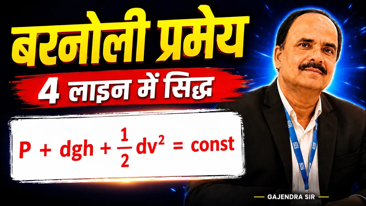
बरनौली प्रमेय , #bernoulli #bernoulli_theorem , #barnoli 11th physics , barnauli ka pramey
174.7K
The derivation begins by expressing work done as P × A × d, where d represents distance traveled. Since velocity equals distance per unit time, this becomes P × A × v. For two points in the flow, the net work done equals P₁A₁v₁ - P₂A₂v₂. Using the continuity equation (A₁v₁ = A₂v₂ = volume flow rate), and substituting mass flow rate (m/density), the equation simplifies to P₁ - P₂ = ρg(h₂ - h₁) + ½ρ(v₂² - v₁²). Rearranging terms yields Bernoulli's equation: P₁ + ρgh₁ + ½ρv₁² = P₂ + ρgh₂ + ½ρv₂², demonstrating that the sum of pressure, potential, and kinetic energy per unit volume remains constant along a streamline.
Click to watch →
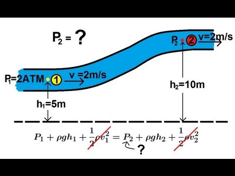
Physics 34 Fluid Dynamics (1 of 7) Bernoulli's Equation
1.3M
To calculate pressure changes when fluid rises in elevation, rearrange Bernoulli's equation to solve for P₂ = P₁ + ρg(H₁ - H₂). For example, if water (ρ = 1000 kg/m³) rises from 5m to 10m elevation while maintaining 2 m/s velocity, the pressure decreases by ρgΔh = 1000×9.8×5 = 49,000 N/m² (Pascals). Converting to atmospheres (1 atm ≈ 101,300 N/m²), this equals approximately 0.48 atmospheres. If initial pressure was 2 atmospheres, final pressure becomes 1.52 atmospheres. This demonstrates how elevation gain directly reduces pressure in static or slow-moving fluids.
Click to watch →
Deep Dive
Aerodynamic applications of pressure differentials, such as how lift is generated on aircraft airfoils.
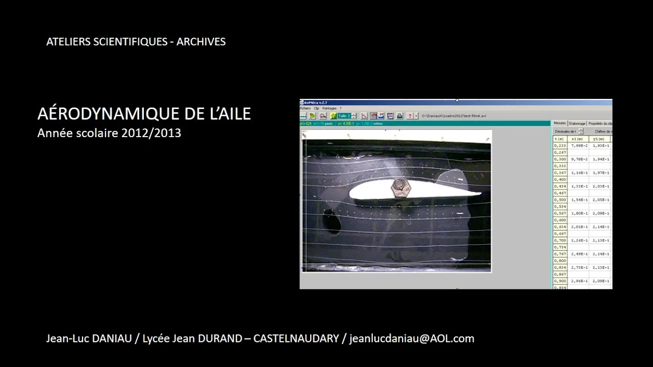
Aérodynamique de l'aile d'un avion
1.9K
Lift (portance) on an aircraft wing is generated by the pressure differential between the upper and lower surfaces. On the upper surface (extrados), the curved shape causes air to accelerate, creating a region of lower pressure (Venturi effect). On the lower surface (intrados), the relatively flat shape results in slower-moving air and higher pressure. Since the extrados experiences lower pressure than the intrados, there is a net upward force called lift. This pressure difference arises because the same volume of air must pass over both surfaces, but the longer path over the curved upper surface requires higher velocity and thus lower pressure.
Click to watch →

¿QUE ES EL DIFERENCIAL DE PRESIONES?
789
The differential pressure (diferencial de presiones) is the pressure difference between the upper and lower surfaces of an airfoil that generates lift, explained by Bernoulli's principle which states that pressure decreases as velocity increases, and complemented by Newton's laws of motion. The lift force equals pressure multiplied by area (F = P × A), and the center of pressure moves based on the angle of attack, which is the angle between the chord line and the relative wind.
Click to watch →

Carburetors a Crash Course
327
Airplanes and helicopters generate lift through pressure differentials created by wing shape. When air flows over an airfoil, it travels faster over the curved upper surface than the flatter lower surface. According to Bernoulli's principle, faster-moving air creates lower pressure. This results in higher pressure beneath the wing pushing upward, creating lift. Similarly, bird wings are shaped to create this same pressure differential for flight.
Click to watch →

Video #19 - Fluid Mechanics - External Incompressible Viscous Flow 1
4.3K
Lift is generated on airfoils through pressure differences created by the shape of the wing. According to Bernoulli's principle, faster-moving fluid has lower pressure. On an airfoil, the curved upper surface causes airflow to accelerate (creating low pressure above), while the flatter lower surface causes slower airflow (creating high pressure below). The resulting pressure differential generates an upward force called lift. This principle explains why wings generate lift during flight.
Click to watch →

SGC Zoom Talk by Peter Gill - Principles of Flight
519
As air flows faster over the top of an airfoil, pressure decreases because molecules have less time to collide with the surface. This pressure difference creates lift. The total reaction force from airflow has both vertical (lift) and horizontal components (drag). Modern airfoils are designed to keep airflow attached for longer, producing lift from both the bottom deflection and the pressure differential on top, resulting in much better lift-to-drag ratios than simple flat wings.
Click to watch →
Deep Dive
Practical engineering applications of the Venturi effect, including Venturi meters, carburetors, and medical aspirators.

EXPERIMENTOS CON EL EFECTO VENTURI | ¿QUÉ ES Y CÓMO FUNCIONA?
343.6K
The Venturi effect has widespread applications across multiple fields. In agriculture, Venturi tubes inject fertilizers into irrigation systems without pumps. In automotive engineering, carburetors use the effect to draw fuel into air streams. Maintenance tools use Venturi principles for oil extraction. Household items like perfume atomizers and aquarium filters rely on this principle. Medical applications include oxygen delivery masks and dental suction units. Fuel pumps use Venturi mechanisms for automatic shutoff. These diverse applications demonstrate how a single physical principle enables countless practical solutions across industries and daily life.
Click to watch →
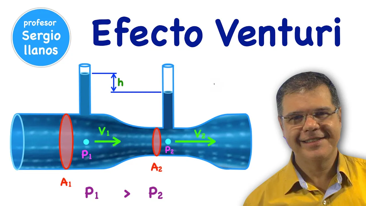
EFECTO VENTURI: ¡Cómo un Tubo Puede Controlar la Presión y la Velocidad del Aire!
1.6M
The Venturi effect has diverse practical applications across multiple fields. In agriculture, Venturi tubes automatically inject fertilizers into irrigation water by using pressure differences to draw solutions into flowing streams. In water purification, ozone generators mix ozone gas with water using Venturi principles. Medical oxygen masks use Venturi effects to deliver precise oxygen concentrations. Carburetors in internal combustion engines mix air and fuel using pressure drops from constricted passages. In motorsports, Formula 1 cars use Venturi-shaped underbody tunnels to create low-pressure zones that generate downforce, pressing tires against the track for improved stability at high speeds.
Click to watch →

Je construis le BARBECUE le plus puissant DU MONDE ?!
242.3K
The Venturi effect describes how fluid pressure decreases when flowing through a narrowing conduit, causing acceleration. Discovered by Giovanni Venturi in 1797, this principle enables aspirating, mixing, and efficient combustion. Applications span aviation (paint guns), medicine (oxygen masks), and automotive engineering (carburetors). In gas appliances, Venturi injectors mix air and gas for hotter, more complete combustion. The video demonstrates building a gas barbecue using plumbing fittings, warning about high-pressure gas dangers. Key components include regulators, T-fittings, valves, and small orifices that create the pressure differential necessary for the effect to function.
Click to watch →

venturi effect
330.5K
The Venturi effect, scientifically described by Giovanni Battista Venturi, states that fluids under pressure passing through converging pipes gain speed and lose head (pressure), while diverging pipes cause fluids to slow down and regain pressure; this principle was applied by Clemens Herschel in his 1889 invention of the Venturi meter, which measures flow rate by detecting pressure differences using manometers, and is widely used in flow meters, carburetors, steam injectors, and sprays due to its reliability and lack of moving parts.
Click to watch →

f2f Hidráulica #18, Principio de Bernoulli #2, Efecto Venturi
236.1K
This comprehensive section demonstrates how the Venturi effect translates into real-world technology. In carburetors, air acceleration through a narrowed passage creates negative pressure that draws fuel into the airstream. Aircraft wings utilize the same principle—curved upper surfaces cause faster airflow above, generating lower pressure that creates lift. Firefighting foam proportioners apply the effect by using water flow through restricted passages to draw foam concentrate into the stream. Each application shows how controlled flow restrictions create pressure differentials that enable essential functions in transportation, combustion, and safety equipment.
Click to watch →
Deep Dive
The limitations of Bernoulli's principle in real-world fluids, introducing concepts like viscosity, boundary layers, and turbulent flow.

Bernoulli’s Principle Explained Through Stories, Not Formulas| From Book to Real life! Sufitramp!
105.5K
Bernoulli's principle has important limitations: it applies only to incompressible fluids and laminar flow without viscosity. Real-world fluids like air are compressible, and real flows often involve turbulence and energy loss as heat. Despite these limitations, Bernoulli's principle provides the foundational understanding for fluid dynamics. When viscosity is present, energy is lost as heat, violating the conservation of mechanical energy assumed in Bernoulli's equation. However, Bernoulli's principle serves as the starting point for more complex analyses in fluid dynamics, demonstrating how fundamental principles can be extended to understand more complex real-world phenomena.
Click to watch →

Lec-10 II FM & HM II ME 3rd Sem II Unit-3(A) Fluid Flow @PolytechnicPathshala
4.3K
This section covers the limitations and practical applications of Bernoulli's Theorem. The limitations include: (1) Flow must be steady (no change with time), (2) Fluid must be non-viscous (no friction losses), (3) Fluid must be incompressible with constant density, (4) Velocity must be uniform across any cross-section, (5) No external forces other than gravity should act on the fluid. In real flows, viscosity causes energy losses that must be accounted for. The theorem assumes uniform velocity, but in laminar flow velocity distribution is parabolic (maximum at center, zero at walls), while in turbulent flow it is logarithmic. The average velocity is used in practice. Applications include channel flow, pipe flow, free jets, and radial flow. Flow measurement devices based on Bernoulli's principle include Venturi Meter, Orifice Meter, Pitot Tube, Rotameter, and Flow Nozzle.
Click to watch →
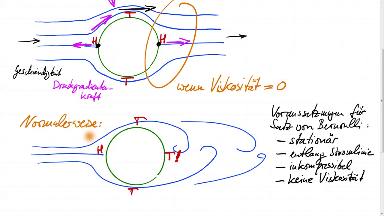
Drei Überraschungen beim Satz von Bernoulli
29.6K
Bernoulli's equation has strict assumptions: stationary flow, constant motion patterns, incompressibility, and zero viscosity. In reality, viscosity causes vortices to form behind objects, violating these assumptions. While theoretically possible under perfect conditions, real-world applications require careful consideration of these limitations. High viscosity or slow flows can produce nearly symmetric behavior, but true inviscid conditions are rarely achieved.
Click to watch →

Mechanical Properties of Fluids, One Shot Video NCERT Class 11 Physics for CBSE Board Term II 2022
134.4K
Streamline flow occurs when liquid particles follow smooth, parallel paths called streamlines, with constant velocity at each point. Streamlines never cross. Turbulent flow occurs when particles move in irregular, chaotic paths with random velocity changes. The transition depends on Reynolds number (Re = ρvd/η). For Re < 2000, flow is laminar; for Re > 3000, flow is turbulent. An ideal fluid has zero viscosity, is incompressible, and has no rotational motion. The equation of continuity states that for incompressible fluid flow, A₁v₁ = A₂v₂, meaning the product of cross-sectional area and velocity remains constant. In steady flow, a fluid possesses three forms of energy per unit volume: kinetic energy (½ρv²), potential energy (ρgh), and pressure energy (P). Bernoulli's Principle states that for an ideal fluid in steady, streamline flow, the sum of pressure energy, kinetic energy, and potential energy per unit volume remains constant: P + ½ρv² + ρgh = constant. Limitations: applicable only to ideal fluids (zero viscosity), incompressible fluids, steady flow, streamline flow, and non-rotational flow. Applications include venturimeters (flow measurement), spray bottles (velocity increase causes pressure decrease), and aerodynamic lift (curved wings create pressure difference).
Click to watch →

Как работают крылья. Общее заблуждение о подъемной силе.
505.6K
Bernoulli's principle states that along a streamline, the sum of static pressure and dynamic pressure (½ρv²) remains constant. As velocity increases along a streamline, pressure must decrease. This is demonstrated using a Venturi tube where narrowing the cross-section increases velocity and decreases pressure. However, Bernoulli's principle applies only along a single streamline, not between different streamlines. This limitation is critical because comparing air above and below an airfoil involves different streamlines with different Bernoulli constants.
Click to watch →
Venturi Effect
Demo Recap
Venturi Effect
0:00- 1
Explains air velocity increases in narrow tube section.
- 2
High velocity leads to lower pressure per Bernoulli's principle.
- 3
Colored water column rises demonstrating pressure drop.
Causal Direction and Viscous Limitations
While Bernoulli's principle accurately describes the relationship between fluid speed and pressure in an ideal system, physics educators often critique how it is taught as a causal explanation (i.e., that 'velocity changes cause pressure changes'). From a Newtonian perspective, the causality is reversed: a pressure gradient (a difference in pressure) is the physical force that actually accelerates the fluid into the narrow section. Additionally, Bernoulli's principle assumes an inviscid (frictionless) fluid. In real Venturi tube experiments, viscosity and boundary-layer effects—governed by the Navier-Stokes equations—introduce friction and energy loss. Consequently, relying solely on Bernoulli's principle overlooks the fundamental forces driving the flow and oversimplifies real-world fluid dynamics.
The concept of fluid pressure, including how fluids (liquids and gases) exert force over a given area.
The Equation of Continuity, which states that fluid velocity must increase when passing through a narrower channel to maintain a constant mass flow rate.
Basic principles of classical mechanics, particularly Newton's laws of motion and the conservation of energy.
The formal mathematical representation of Bernoulli's Equation and how to solve for pressure and velocity changes quantitatively.
Aerodynamic applications of pressure differentials, such as how lift is generated on aircraft airfoils.
Practical engineering applications of the Venturi effect, including Venturi meters, carburetors, and medical aspirators.
The limitations of Bernoulli's principle in real-world fluids, introducing concepts like viscosity, boundary layers, and turbulent flow.
172.8K views2.3Klikes2:13@physicsdemosOriginal Release: 2016-08-20
this is a Venturi tube I've got a source of uh air that'll come in to this side of the tube it'll pass through this region where the tube is wide and then here where the tube is quite narrow and then back to wide again since the same amount of air has to pass through this wide cross-section as passes through here the namely the volumetric flow rate has to be the same the number of cubic cm per second passing this spot has to be the same as the um volumetric flow rate that passes this spot and because this spot this spot has a smaller cross-sectional area the air has to flow faster here so we've got a high velocity region here a low velocity region here but beni's principle says that the higher the velocity the lower the pressure so in this spot here contrary to what your intuition might say instead of the pressure being high here the pressure is actually low and we can demonstrate that using this colored water I filled the bottom of these uh this this uh u-shaped uh glass tubing with water that has a little bit of food coloring added to it what you'll see is uh when we turn on on the air this uh column of water in the middle will rise because the pressure here is lower and essentially acts as a suction for um for for the water so this one will rise higher than either the other other two so that's a Venturi tube a demonstration of the Bern's principle and um very important in in a lot of areas of fluid dynamics
Up Next

15:21
Principles of Flight: Aerodynamics Explained for Pilots
@ERAUSpecialVFR
784.5K views•2016-08-25

22:39
Fluorescence & Jablonski Diagram | Molecular Photophysics
@yairmeiry
192.2K views•2012-01-12

32:32
NMR Spin Physics I: Zeeman Effect, Resonance Condition & Larmor Frequency
@nptel-indianinstituteofsci8064
2.3K views•2024-01-17

27:14
Entropy and the Second Law of Thermodynamics Explained
@veritasium
27.5M views•2023-07-01
Related Study Plans & Knowledge Roadmaps
Structured learning paths in Physics
physics
Analytical Mechanics: Lagrangian & Hamiltonian
01Mathematical Foundations: Calculus of Variations
02From Newtonian Mechanics to Constraint Dynamics
03The Principle of Least Action & Lagrangian Mechanics
+ 3 more learning modules
28h6 modules
Explore Roadmap
physics
General Relativity (Spacetime & Cosmology)
01Foundations of Relativity: Special Relativity
02The Geometry of Spacetime: Equivalence Principle & Curvature
03Einstein's Field Equations: The Mathematics of Gravity
+ 2 more learning modules
55h5 modules
Explore Roadmap
physics
Chaos Theory: Pendulums, Bifurcation & Limits
01Foundations of Classical Mechanics and Pendulums
02The Transition to Nonlinearity and the Double Pendulum
03Core Principles of Deterministic Chaos
+ 3 more learning modules
18h6 modules
Explore Roadmap
physics
Optics (Lenses, Wavefronts & Instruments)
01Foundations of Light and Geometrical Optics
02Mirrors, Lenses, and Image Formation
03Wave Optics: Wavefronts and Interference
+ 2 more learning modules
28h5 modules
Explore Roadmap