
![✅tutorial solidworks 2016 ►ejercicio #1 [FACIL]](https://i.ytimg.com/vi_webp/t3P3TSy9sVA/maxresdefault.webp)















![[製品紹介]3DEXPERIENCE CATIAによる射出成型金型設計](https://i.ytimg.com/vi/eWqT5qClv0M/maxresdefault.jpg)

This video demonstrates how to design wind turbine blades in SolidWorks by importing airfoil data from airfoildb.com, scaling the coordinates to achieve a 3-inch chord width, creating cross-sections using curve through points or image tracing, and then using loft features with guide curves to create the twisted blade profile with a 16-inch total length and 1.5-inch hub attachment.
SolidWorks Wind Turbine Blade Design Tutorial: Airfoil Lofting
Added:Basic SolidWorks Navigation and 2D Sketching: Familiarity with reference planes, sketch relations, and basic 2D sketching tools in SolidWorks.
Fundamentals of Lofting in CAD: Understanding how the loft feature creates 3D shapes by blending multiple 2D profiles along a path.
Basic Aerodynamic Concepts: Familiarity with airfoil terminology such as chord line, leading edge, trailing edge, and angle of attack.
Working with Curves and External Data: Knowledge of importing XYZ coordinate data (such as coordinate files for NACA airfoils) to generate curves in CAD software.
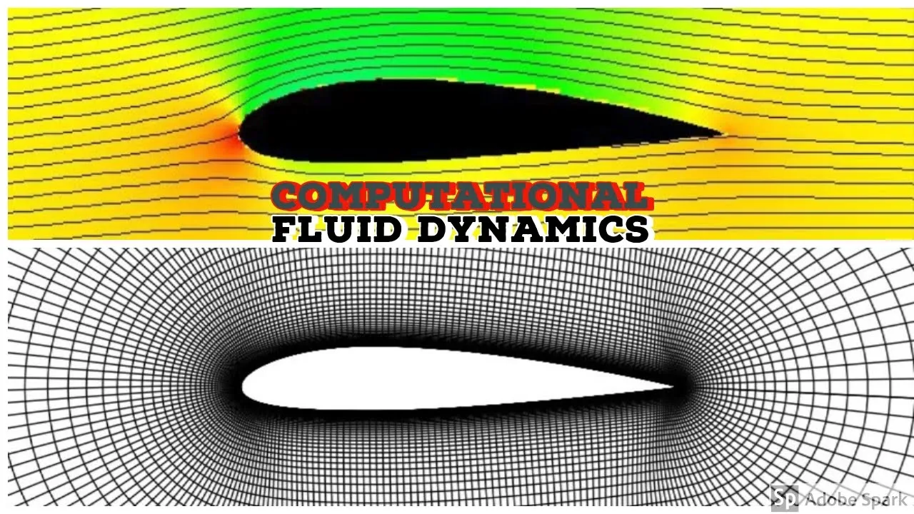
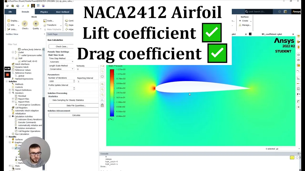
Computational Fluid Dynamics (CFD) Simulation: Using tools like SolidWorks Flow Simulation or ANSYS to analyze aerodynamic performance, lift, and drag of the designed blade.
Finite Element Analysis (FEA): Evaluating the structural integrity of the blade under aerodynamic and centrifugal loads to check for stress concentration and deformation.
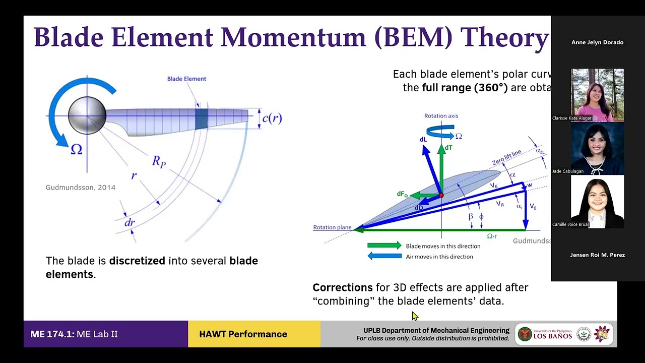
Blade Element Momentum (BEM) Theory: Applying aerodynamic mathematical models to optimize the chord and twist distribution of the turbine blade for maximum efficiency.
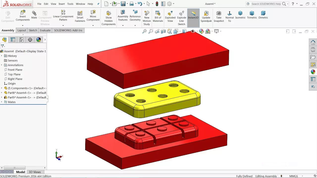
Manufacturing Preparation and Mold Design: Designing two-part molds in CAD for composite layup fabrication or preparing the model for additive manufacturing (3D printing).
116.5K views1.1Klikes26:48Original Release: 2014-12-01
this is Dan Abbott I am making this video as an aid for the comp 115 technical graphics for composits class at Southern main Community College uh this is toh help you with the wind blade uh exercise that we're doing the intent here is for each of you to design a wind Blade with a different cross-section and possibly Different Twist and other characteristics the basic Dimensions I want you to use are indicated in this AutoCAD drawing and the reason for the limitation and this is inches now the reason for this limitation is we're planning on vacuum forming these blades and our equipment is a uh going to allow us a maximum blade length of 18 in so being a little conservative with 16 16 in total length from the bottom of the or the end of the Hub out to the tip of the blade itself the widest point the cord on the cross-section is going to be 3 in and we'll have it tapered down to8 in overall we're after and here's a um an example of one in solid works we're after a shape that looks something like this and if you notice the front view is looking at the small end looking down the blade and the reason for that is I would like to print some of these in fact if you're you may hear some sound in the background right now and there's a 3D printer with the stepper Motors making that sound printing this particular blade in two pieces in order for that to work as well as possible what you want to do is start with the front view being the crosssection so what I want to do is to show you some techniques for locating a cross-section um a variety of cross-sections and bring them into solid works either as a uh curve through points or bringing in an image and then tracing that image in solid so we'll start by going to a website called airfoil db.com and airfoil is the reference to air foils mostly these are airplane based air foils but the basic shape of the basic cross-section is used in horizontal wind EMS um quite frequently so we're going to look there for a basic shape and the DB is a database this website was really set up for hobbyists who are doing uh radio controlled um airplanes but if you get out of the browse and search area this website it has a large number of air foils and if you just kind of drag over you'll get a sense of what the different shapes are so what I want you to do is to go through and this is just starting with the A's ah's in fact and there's uh just thousands of these things in here so I want you to look through and find something unusual find something interesting that we can try as a an experiment so um I'm just going to grab 79100 C air foil looks pretty good to me so I'm going to grab that and what happens when you pick it is it gives you an image and it also gives you a means of downloading this image in in a format that can be brought into another program and the DAT format is text based indication of the X Y and Z locations and by the way all of these have a unit length from the tip of the air foil to the tail of one unit so depending on how you bring it into solid works that will either be one inch or one millimeters so we're going to go through first and change that so that that comes in at the 3 inches that we want one technique is just to do a screen capture and then to bring the image itself into solid works and trace it the other though is to go to the DAT file if we were to open that file and take a look at it it's a series of X and Y coordinates starting with one zero also has the name of the uh particular air foil right here in order for us to use this in solid works we need a couple of things one we need a third column that has zeros in it and we need to get rid of that header material so what I'll do go back to the original page and instead of selecting dat and opening it up we're going to rightclick and then we're going to do a save linked content as gives us an opportunity to save this file it's going to be saved with the DAT extension and change that to a txt extension and I'll put it in the downloads file and just so I can keep track of it with something more descriptive I'll call it 70h ah 79-100 which is the number that it was given to it then save it now I need to modify it a little bit so I'm going to do that by going into an Excel spreadsheet here's our spreadsheet right here and I'm going to go and open up that file to do that I need to change the file type from the Excel files to a text file type now when we go down looking for the ah in our downloads folder which is where I put it it's right here I'm going to go ahead and open it up now as I'm opening it up I'm going to have some decisions to make one of them is whether to bring it in delimited which I want to do that simply means you want to put it into columns based on a delimeter of some kind I go to next and now I get to pick the kind of limiter and since this is comma delimited I'm going to change it from tab to comma and it shows me down here that it'll come in in two columns I go to next I now finish it and I've got two separate Excel spreadsheet columns here the first thing I'm going to do is to rightclick and delete that row that has the information in it about the header material so now we're starting with one which is the overall cord length and zero and then after that it's a series of XY coordinates solid works is going to expect a um Z coordinate as as well so we just go ahead and put a zero here after that zero is in there I'll just right click and copy it drag down through to the end of this column and add a zero of the z-axis zero so we'll have a flat pattern when we bring it into solid works just cover everything right click and then do a paste once you've done that there'll be zeros in all these locations now I really want all of these values increased by uh factor of three so that I can have a chord length of three and then end up with the overall shape the three meaning that 3 in right here on the maximum length um an overall shape that's 16 inch long and then the 3 in wide I can do that here with a formula uh or I can do that when I bring it into solid works by just scaling it up what I'm going to do is to save this file and I'm going to save it on my computer as a a CSV comma delimited file and I I need that because it has to be comma delimited so I'll go to my downloads file and I um will call this ah 90 uh 79-100 some features might be lost I'm going to do it anyway now I'm just going to close out this Excel spreadsheet file um say don't bother to save it I've already got it I'll close this one out as well so we don't have the spreadsheet open it at all what I'm going to do is to change the extension on this CSV file and I'm doing this because solid works won't recognize it if it doesn't have a txt extension now this is one we're going to use now if I open that file up as a text file you'll see that it consists of columns separated by commas which is what I need for solid works now I'm going to go back to solid works I'm going to start a brand new file it's going to be a part file and I'm just going to make make sure that it's in inches so when those when that um those curves come in those points come in they're going to be measured in inches I'm going to go to features and what I'm needing to do at this point is go to the curves menu and under the curves menu there are two types of Curves a helix and spiral or a curve through XYZ points and this is the whole point of going through that Excel spreadsheet downloading the DAT file Etc if I go and browse for that file I'm going to look for it it's looking for an sldd CRV file which is not the file extension that I placed on there I made it a text file so we'll go up to downloads which is where I had it stored that's the file that I just created I bring it in pick okay and it literally sketches out that shape that you just saw now it does that on the front plane you can see that looks very much like the shape that we have right here so go back to solid works and what I'm going to do now is to use that uh curve that was brought in and I'll use that curve by converting it into a sketch so I'll go to the sketch function pick the sketch Bunch button say let's sketch on the front plane convert entities select that curve that was brought in pick the check button and now what you can see is I have a closed shape fully defined that is based on those curves that came in and at this point I can use that as a way of creating a um Loft and that Loft will then be our air foil the other technique that you could use for this we'll just I'm going to pick okay here and I'll start a new file another part file also in inches so other thing that I could do is to go over and actually get an image of some kind now there are a number of ways to get images of course in this particular case what I'm going to do is just to make it larger so it looks like that so I can get a pretty good look of look at it on the screen and then what I'm going to do is a uh as a print screen actually I happen to have snag it so what I'll do is print it using snag it which allows me to crop it as I'm copying it you could do a print screen and bring it into a piece of software and crop it there if you wanted to um in fact let's do this just as an image file so instead of clop copying it to the clipboard I'm just going to copy this and then go to the snagit file and under here then it asks me what I want to do with it I'm going to do a save as and I'll create a JPEG file out of this one and I'll put that since I've been using my downloads folder to put everything else I think that's where I'll put this as well uh so my downloads folder which is here and here okay now I'm gonna change the name of this and I'll give it the same name I gave the other files ah 79-100 it's a JPEG file we'll save that now I don't need this anymore I'll just close that out and I'll minimize this and minimize this so now I'm back in solid works in order to use that what I need to do is to start a sketch this time I'll start a sketch on the front plane and then before I actually start sketching anything what I'm going to do let's go to the tools pull down and under the tools pull down there's something thing down here called sketch tools and under sketch tools there is a tool called sketch picture which is off the screen the way it's set up right here me see if I can get it to show up okay tools sketch tools well down at the bottom it's just off the screen here a little bit I'm going to make uh I'm going to move my now I guess I can't get it down without changing the way I've got my set up well I'll tell you that if you right now you're looking it says close sketch to models you know check sketch for feature if you get on a couple more there's a uh an option called sketch picture which is what I'm selecting right now when you do the sketch picture it's asking you to go and find the sketch you want to use the one I want to use is right here so I'm going to open it up and it just drops it right into my sketch and it looks like that now this one because I just did a screen capture it has no idea how how long this is so I'm going to start now by just picking this bringing this in going to draw a center line goes to my origin I'll bring it out put a dimension on it because I want this overall to be three inches so I'm just going to give it that a dimension of three and then I'm going to go and grab my image and when I grab the image and double click on it it allows me to to reduce the size and to move it so I'll move it so that point is right about here and then I'll scale it down so it's about the right length and this is an approximation I have to say this is all done by I but you can still be uh come pretty close by just going back and forth a little bit deciding right about there how close you need to get and I think that's good enough so now that I've got this what I would do is go and I just sketch on top of that shape and that sketch is going to be something I'm going to do with a spline the spline command is right here when sketching with um solid works and sketching an existing on top of an existing image sort of nice to have a Target so since this is three let's just say I want to go um every I don't know quarter inch or so so let's take uh and create 13 divisions here by drawing another Center Line we'll draw that center line through the origin so it's nailed down to the origin and then I'm going to use a linear sketch pack pattern the x- axis in this case requires that I have another sketch so I'm going to draw another line that comes out through oh I've already got a line there don't I oh yes I do sorry so I'm going to go back and do a linear sketch pattern and when it asks me for the x axis I'm going to select that line that I've already drawn and I will make the distance between a quarter of an inch and we'll put 13 of them in there pick okay and now what it did is it oh uh I'm going to back up here and the reason I'm backing up is because I wanted to pick the line that I drew as my Direction but I didn't want that to be the line that was actually being um arrayed so go back my x-axis is going to be that line right there now the object that I want to array which I need to select down here is going to be this line the one going up like that I want a quarter of an inch space so 0.25 and I want 13 objects so I'm going to go to 13 so now you'll notice that I've got these 13 lines going through here and the only reason I put those there is just to have a sort of logical Target for placing points I actually probably want more points here because of the way that turns around so let me go back and do another linear sketch pattern and now instead of a quarter let's just go with 0.005 and we'll put a number of those in here 05 not offset but linear also the x axis and we still want is our entities to pattern to be that line right there we'll go up 0.005 and uh 054 oh let's just say we want 10 of those and that just gives us um a little more uh control as we come through the area that's going to change pretty dramatically so now we'll go back over here I'll do a spline I'll start the spline out at the end here and I'm just going to go and just select a point on each of these lines that is as close as possible to going through my sketched image if I come here here I guess you don't really need to see me do the whole thing but I do want to get to the point about there so what I'm trying to do is to stay as much as possible in the center of this and because this starts to change a little more dramatically I'll go along until I have to make a change so now I've got a spot here here here and this is really where this dramatic change is most noticeable so you can see what it did is it wrapped around the nose a little more um like the actual sketch itself so you just go through and then finish this up I'm going to pause this so now I'm at the end when I'm done I just press the enter key and now I've got a sketch that I can use I'll come back out of here and you can see that sketch a lot of things going on in it but you can see the basic sketch itself with all those lines those lines can be hidden if you don't care to see them so my sketch looks like this it's a sketch on the front view so what I'm doing now is I'm going to going to go and make a few planes and then uh and then change overall the length of that now what I need to do is to create a plane that I can draw the small end of the wind blade on and uh if you've been paying attention you might notice that I've actually switched overall shapes I've opened up a file that I've already used to create a wind turbine so I can maybe make this video a little bit quicker so the first thing I need to decide is this do I want this blade to turn counterclockwise or clockwise if I want it to turn counterclockwise what I want to do is to add the small end out here coming toward the the screen if I wanted to turn clockwise I need to add the small end on the other end so let's go with clockwise on this one since that's what most wind blades do seem to be doing so we're going to go over to Features reference geometry and under reference geometry I'm going to say I'm going to add another plane since we started by drawing on the front plane I'll select the front plane as one of my references and then I'll type in 12 and a half 12 1/2 is the length I want this blade to be it's coming out instead of going in so I'm going to go over the left and pick flip now that plane gives me a place to draw the small portion of the uh wind blade on I'll go over to the sketch function pick the sketch button and I'm already on that plane so now I'm going to look at this let's look at it instead of from the front let's look at that from the back so that the small piece is closer to us as we're viewing it first thing I need to do is to convert the entities themselves and then I'm going to scale them down if we look at our original wind blade shap AP the small end8 the largest end which is what we're creating right what we already created right there is three so if I want to figure out how far to scale that I'll take 08 divide by three to determine what the ratio would be 26 so if we make it 27% it'll give us almost will give us the the 08 so go back to solid works first thing we need to do is to do a convert entities let select that sketch shows up over here I pick the green check and it converts the entities shows them there now I'm going to go to the move entities drop down little arrow beside it pick scale entities put a window around all of those sketch entities pick scale about over in the properties manager I'm going to select the origin since that's where I placed this initially uh and because I've already done this once 0 27 comes up as the default that's the value that I got when I divided 08 by 3 I'll pick okay looks like that now most wind blades have a Twist to them there are two ways to place the twist one is to do it here and one is to do it with a um a Twist option of the flex feature instead I'm going to do it right here and because I want this to go clockwise the appr appropriate way to tilt this is to tilt this end right here down uh I'm going to go about 10 degrees anywhere from from uh 5 to 20 is considered okay so we're going to twist this 10 degrees for right now so I'll go back up to the move entities drop down this time I'm going to pick rotate entities put my window around all of them Center rotation will also be the origin we'll go over and type in a 10 for 10 degrees and that's the opposite direction that I want to go so I'll go and put a negative in here so again this is when we want a clockwise rotating wind blade looking at it from the small end down to the wide end with the larger part of the profile to the right now that I've got that we'll come back out I've got my two sketches I'll go over to the features indicate that I want to do a lofted boss or base I'll pick one of the sketches near the top the other sketch near the top and it comes in like that and if we now I'm just going to hide that sketch and that plane so now if we look at it straight down from one end you'll see we have a shape where this end twists down a little bit so that whole twist comes down through the blade like that and there's our basic our functional fundamental part of the blade so now what I'll do is add the uh base the circular base that we're going to use to attach the wind blade to the hub to do that I'm going to add a plane away from this surface um 2 and a half inches away actually already put that in so we'll come over here and look at it there it's just a reference plane and then I'm going to sketch on that reference plane what I plan to sketch on that reference plane is that Circle right there so looking at it from the front what I did was sketched a construction line that went from the origin to the tail then I placed a circle on that construction line and I made sure that the circle itself right through the origin by adding a relationship gave it a diameter of 1.5 since I want a 1 and a half inch Hub at the end and now that it's in place what I want to do is to make a loft that goes from this surface to this surface right here I need another sketch of that shape so I'll go into the sketch function side let's sketch on that surface right there do a convert entities of that entire face now I have another sketch and you can see it over here it's just sitting sketch 11 that's called sketch three is the circle sketch 11 so if I do a laof from sketch three to sketch 11 I'll have a that shape I won't really care for it though and I'll show you why if I come over here to the lofted base I say do a loft from here to the circle it goes straight down like that and what I want is a little more control I don't want that to curve in I want that to kind of sweep down and a reverse OG so that it looks a little better nothing particularly wrong with that I just don't happen to like it so we'll get out of the Loft itself I'll go back and now what I need is to add a couple of guide curves so I'll do that from the top view looking down at it from the top I'm going to go back and sketch on the top plane when I sketching the top plane I'm going to start by just sketching a line that goes from the origin right down to my circular sketch now what I want to make sure is that end point right there which you see right now can go almost anywhere I want that to be have a pierce relationship with that Circle to make sure that it goes through that Circle so I'm done with that sketch now I want to put another sketch and this new one is going to be also on the top [Music] plane okay so I've got my profile another profile and then a guide curve so go back into sketches go back to the top plane looking at it directly from the top I'm going to sketch a spline that goes kind of in like that over like this down like this I don't really want it to go quite all the way but that's more or less the shape that I want so now I'm going to take the end point of that spline holding the control key down I'm now going to select the circle and once again I'm going to create a pierce relationship so it pierces the circle on the same plane do the same thing at this end take that and the other sketch that I created have a pierce relationship we've already got a coincident relationship there so let's go back and do that again okay there is our Pierce relationship is already set so now it's pierced yeah that point is on that surface right there so now if I look down at it from the top I'm GNA do go and do a little little graphic problem here I'm just going to adjust that so that it comes down a little more smoothly so I'll have it kind of continue on for a little while come down transition into this I like the look of It kind of a reverse OG pick okay so I've got four sketches that are going to be involved with this next Loft and those four sketches will allow me to do a lofted base pick a profile pick a profile go down to guide curves pick that guide curve which what you see kind of makes the whole thing go off squirly so I'm going to add the straight guide curve as well so now one Edge is going to be straight the other one's going to go down in Reverse OG that's my basic shape right there now if I go over and extend this by sketching on that surface doing another convert entities of that surface sketching on that surface convert entities of that surface now that circle is going to be the same size as the one that was originally created with we'll go over here and do an extruded boster base I'll go out an inch and a half inch and a half gives me what I want and that's my entire wind blade now what I'm going to do is to split it so that I can print it because the printer I'm going to print it on will not print the entire length of that wind blade which at this point should be about 16 and 12 inches let's go and just check that going to measure it from that surface to this surface here 16 and a half inches that's um is well in within our 18inch limit I don't want to get too close to that 18inch limit so we're going to be well within our 18-inch limit so we have a 16 and 1 12 inch uh wind blade because my printer won't go up above N9 Ines I would then put a plane in the middle and then add What's called the split relationship into split it into two that's enough for this one
Up Next

5:43
Measuring Power From a KidWind Turbine With Multimeters
@casejmu116
383 views•2024-12-02

12:54
Triumph of Orthodoxy Icon: Byzantine Art & History Explained
@BenCallan
2.1K views•2024-08-06

9:49
FastAPI vs Flask vs Django: Choosing the Right Python Web Framework
@TechWithTim
302.5K views•2024-05-26

1:42
Game of Thrones Opening Credits: A Cinematic Analysis
@gameofthrones
46.3M views•2011-04-18
Related Study Plans & Knowledge Roadmaps
Structured learning paths in General & Interdisciplinary Studies
general-studies
Elevator Engineering: History, Physics & Cities
01From Hoists to Safety Brakes: The Dawn of Vertical Lift
02Hydraulic vs. Traction: The Engineering Physics of Elevators
03Modern Speed, Safety, and Algorithms
+ 2 more learning modules
12h5 modules
Explore Roadmap
general-studies
Rubber: Material Science, History & Geopolitics
01Origins of Natural Rubber & Mesoamerican History
02The Chemistry of Natural Rubber & Vulcanization
03The Geopolitics of the Rubber Boom & Colonization
+ 2 more learning modules
12h5 modules
Explore Roadmap
general-studies
Containerization: Evolution, Logistics & Trade
01Ancient Trade & Bulk Cargo: Amphorae to Barrels
02The Industrial Revolution & Cardboard Packaging
03The Containerization Revolution: Malcom McLean
+ 2 more learning modules
12h5 modules
Explore Roadmap
general-studies
Textile Tech: Evolution, Labor & Global Impact
01Pre-Industrial Textiles: Handloom & Cottage Industry
02Mechanization: The Spinning Jenny to the Power Loom
03The Factory System & Global Labor Transformation
+ 2 more learning modules
10h5 modules
Explore Roadmap