





![[ 번역 ] MOOC - STM32Cube.AI workshop (2/2)](https://i.ytimg.com/vi/hau_HaahwZ4/sddefault.jpg)







![[ STM32 ] Bài 17: I2C với STM32 Phần 01 Lý thuyết về I2C](https://i.ytimg.com/vi/KUcw2TBnrT4/maxresdefault.jpg)

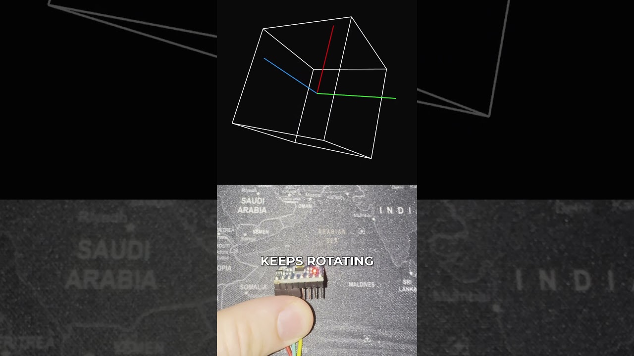




This video demonstrates how to configure I2C communication on STM32 using the HAL library to interface with the MPU6050 IMU sensor, covering pin configuration (PB8/SCL, PB9/SDA), I2C peripheral setup with standard mode, device address calculation (including the read/write bit), and register manipulation using memory write/read functions to configure sensor parameters like gyroscope full-scale range.
STM32 HAL I2C Tutorial: Interfacing MPU6050 IMU Sensor
Added:Basic understanding of the I2C communication protocol, including master/slave roles, addressing, and read/write operations.
Familiarity with C programming, particularly bitwise operations (AND, OR, shift) used for register manipulation.
Fundamentals of STM32 microcontrollers and the STM32CubeMX/HAL ecosystem for peripheral configuration.
Basic concepts of Inertial Measurement Units (IMUs), specifically how accelerometers and gyroscopes measure motion.
Implementing sensor fusion algorithms (such as Complementary or Kalman filters) to combine accelerometer and gyroscope data for stable orientation tracking.
Configuring non-blocking I2C communication using STM32 HAL with Interrupts (IT) or Direct Memory Access (DMA) to optimize CPU utilization.
Sensor calibration techniques to identify and compensate for zero-g offsets and gyroscope bias drift.
Utilizing the MPU6050's onboard Digital Motion Processor (DMP) to offload complex orientation calculations from the host STM32 microcontroller.
36.7K views378likes13:48Original Release: 2022-05-02
hello guys in the previous video we set up a serial wire viewer so we can easily use printer function next we have to work with the i square c protocol to communicate with the imu sensor first we have to open iuc file to configure isqrc peripheral so in this specific board we have pb8 and pb9 we have to configure these two pins as serial clock and serial data lines if you have other microcontroller boards in that case you just need to check the datasheet to find the appropriate pins next as you might notice we have yellow corner color meaning that we haven't fully configured i square c protocol so we need to go to connectivity i2c1 and among these options we have to choose i square c then we will have a new window that shows different parameters right now we don't need to touch any parameters because the default values are are enough for us it's worth mentioning that in in icecreasy protocol we have different speed modes so we have a standard mode fast mode and the fast mode plus but standard mode is more than enough for us so i will keep it as it is next we will save our our configuration by pressing ctrl s remember my decision yes so the generation of the code is over so we can start coding sqrc protocol next i ask you to open the following folder drivers hub driver include then inside of this we have this file that comprises all functions all markers everything related to a square c protocol so if you scroll down and on these lines you will find the declaration of different functions in order to proceed further i want to clarify one thing in general in in the hull api we have three working modes we have polling modes we have interlab modes and dma when using polling mode we manually trigger i square c protocol using these functions but when using these functions cpu will be busy handling these functions so we can do nothing but just to wait the end of the end of the execution of these functions that's why we have blocking mode but we can also use interrupt modes when we trigger i square c but we don't need to wait after using this function we can we can immediately switch to other actions for instance if we use this function we we ask i square c protocol to transmission data then we can do other things but when the transmission is over and after the end of the transmission there will be some interrupt service routine function that will be invoked so that's why we have non-blocking mode and finally we have also dma mode which is using direct memory access but right now we don't need to bother about it because i will explain that later so first we will work with this functions at the beginning we will use this function just to check that we connected our sensor properly to the microcontroller that we've powered everything properly so let's copy all of that we need to paste it within the main function after all these initialization functions so next we have to provide all the arguments so first we go to this function so we need this variable so we'll paste it here next we need the address of the i square c device just open the data sheet of of the device that you're using in my case i have the following mu sensor and i just search for address so we have the full link address as you see also in this sensor we have the following pin so by setting and resetting this pin we can change the address to be specific the last bit of this address value but in my board the state of this pin is low so i have the following address so i just copy and i will paste it here also as we discussed we have address of the device after that itus i square c master the microcontroller has to send the the read write bit but when using this function we have to encapsulate these two data pieces as just one byte so in my case i would just add zero at the end or we can do like a left shift operator by one bit then we have let's say plus zero and this has to be zero b meaning that this is the binary number then we have to specify files i will just try to connect once to the i square c device then time as a time mod i will set 100 milliseconds and as you might notice this function returns the following the following data type so just to create just a temporary variable to check the returned value so i will check if so right now i ask you to connect your iscsi device to your microcontroller and don't forget to power your device next we just need to connect the microcontroller and we press debug um okay therefore here we need to provide the address of the variable so we will need to put ampersand symbol so open itm data console then we can just resume and as you see we have the following message meaning that we connected the iscsi device properly to our microcontroller but if you get this message just check cables just make sure that you powered on the ice crc device properly that you didn't mess up with sda and this with serial data and the serial clock lines let's continue first i just want to eliminate all these warnings so for that we just need to put brackets these yellow warnings are gone next we need to open that file again so we have to work with other functions to to write and read i square c device if you have just a simple i square c device you just need to write and read but in most of the cases we have to deal with the internal memory of the sensor we or in other words we have to work with the registers in that case we need to work with the following functions memory write and memory read these functions are used to transmit and receipt receive some data in a when in master as well as in slave mode but in our case we will work with the following functions to read specific register to write to the specific register within within the sensor so let's copy that so we are writing so read to write bit has to be zero and we have the following address next we need to specify the register that we want to write for that purpose we have to work with the data sheet of the sensor so in my case we i will work with the following document before reading the sensor measurements we first need to configure the sensor so let's open this a register so this register has first of all the following bits that allow us to configure the bandwidths of accelerometer and the gyroscope but i will keep it as it is as the default value next we have to work with the following register to configure the range of the gyroscope full scale range so by default all the values is zero so i want to set the falling full scale range meaning i have to set one to this bits so these bits are located in this position bit 4 and 3 so i have to set this bit to 1 and we have the following register so we have 27 as a memory address size in my case i have just a one byte so i keep it as is to one and we need to provide the other sort of buffer so as i as we discussed we have to set this speed to configure the full scale range to this value so we have the following value and of course we have to insert ampersand symbol and we just want to send just a one single data one single byte so i'll keep it as just one as a and as a time mod i will set 100 milliseconds so let's do the same trick press debug and we have another error okay need to remove this so as you see we got the following message meaning that we successfully load the following data to this register of the imu sensor
Up Next
8:03
How to Flash STM32F103-Based Flight Controllers with ST-Link
@kiradite4321
307 views•2020-04-21

30:32
Ultrasonic Transducers: Resonant Frequency Measurement and Horn Design
@imajeenyus42
229.9K views•2017-02-22

54:16
Polymer Environmental Degradation: Mechanisms & Stabilization
@iit
1.8K views•2012-07-10

33:39
How a Student's Question Saved a NYC Skyscraper from Collapse
@veritasium
22.8M views•2025-04-26
Related Study Plans & Knowledge Roadmaps
Structured learning paths in Engineering
engineering
Building Acoustic Levitators: Physics & Arduino
01The Physics of Sound and Standing Waves
02Piezoelectric Transducers and H-Bridge Drivers
03Arduino Programming: Generating 40 kHz Signals
+ 2 more learning modules
14h5 modules
Explore Roadmap
engineering
Building Peltier Cloud Chambers: Particle Tracks
01Cosmic Rays & Cloud Chamber Physics
02Thermoelectric Cooling (TEC) Fundamentals
03Custom Liquid-Cooling Loop Design
+ 2 more learning modules
18h5 modules
Explore Roadmap
engineering
Yagi-Uda Antennas: Modeling, Build & VNA Test
01Introduction to RF and Antenna Fundamentals
02Yagi-Uda Antenna Design Principles
03Antenna Modeling and Simulation in 4NEC2
+ 2 more learning modules
18h5 modules
Explore Roadmap
engineering
ECG Monitor Design: Op-Amps, Filters & Noise
01Electronics & Breadboard Basics
02Op-Amps and Instrumentation Amplifiers
03Bioelectricity and ECG Fundamentals
+ 2 more learning modules
18h5 modules
Explore Roadmap