This tutorial demonstrates how to build a 5-axis analog joystick controller using a breadboard, Arduino Leonardo, and five 10k potentiometers. The setup involves connecting each potentiometer's outer terminals to the breadboard's power rails and the center terminal to separate analog input pins (A0-A4). Power connections are made via jumper wires from the Arduino's 5V and GND pins to the breadboard rails. The Arduino sketch requires the Joystick library and must be configured for the Leonardo board. After uploading the sketch, the controller can be calibrated through game controller properties to create a functional prototype suitable for simulator games, pedals, hand controls, or flight simulation applications.
DIY 5-Axis Analog Joystick Controller With Arduino
Added:Deep Dive
Basic understanding of the Arduino platform, including how to write, modify, and upload sketches using the Arduino IDE.

Arduino Coding for Beginners | How to Program an Arduino?
591.5K
Arduino IDE (Integrated Development Environment) is a free software used for writing, compiling, and uploading code to Arduino boards. It functions as a lightweight text editor where you write your code. The code written inside Arduino IDE is called an Arduino sketch. Arduino programming uses a language similar to C++ and is designed to be very easy to learn. The code is first compiled into machine-readable language and then uploaded to the Arduino board.
Click to watch →
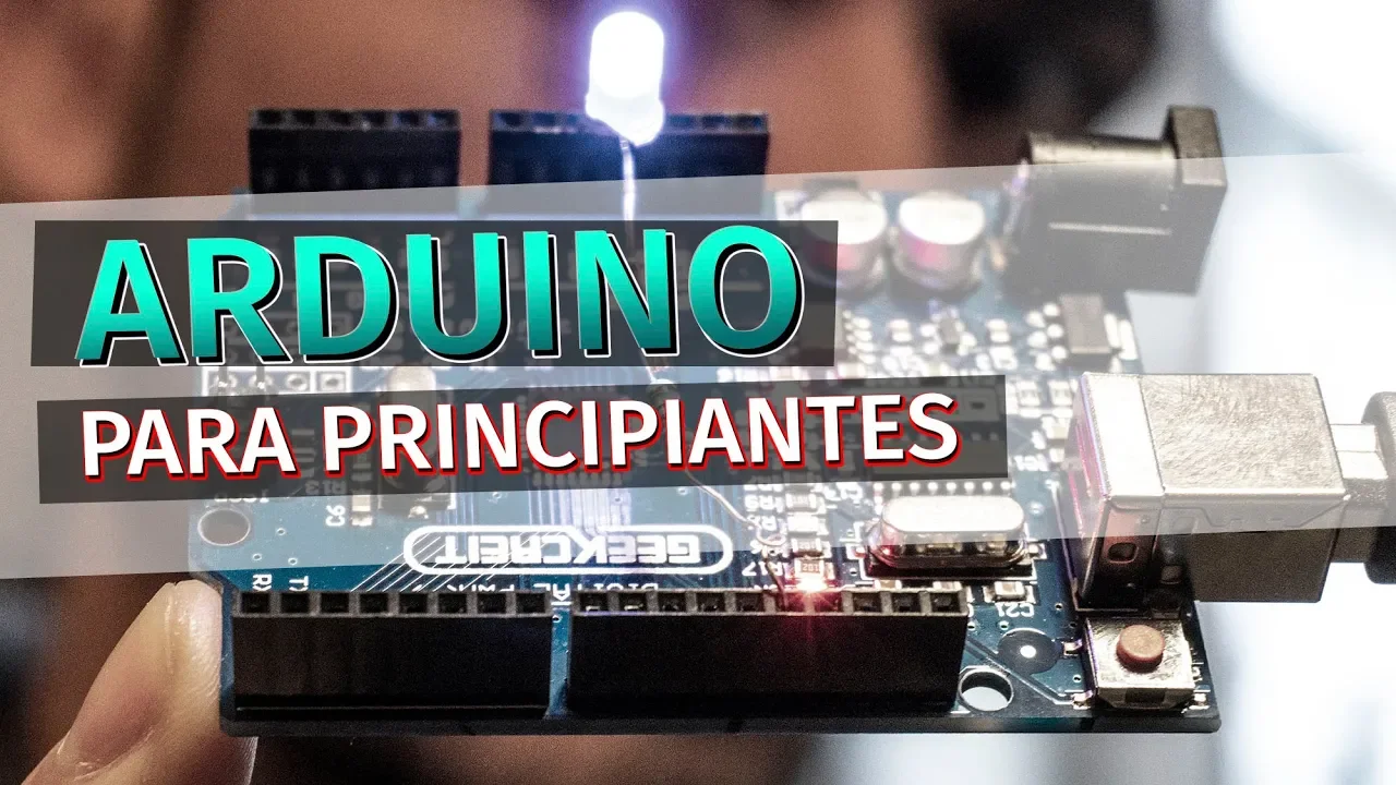
Arduino para principiantes | Instalar el IDE y comprender lo básico
340.7K
Arduino is a popular, economical electronics platform consisting of hardware (programmable boards with input/output ports) and software (Arduino IDE). The hardware is open-source, allowing users to create their own boards. The IDE runs on Windows, Mac, and Linux. Arduino uses a simplified C/C++ programming language, making it accessible to beginners. Applications include weather stations, automatic lighting systems, and various projects. To use Arduino, download the IDE from the official website and install it. The IDE provides access to code examples, documentation, and project ideas. Arduino programs consist of two main functions: void setup() (runs once at startup for configuration) and void loop() (runs continuously for main functionality). The Blink example demonstrates fundamental programming concepts including pinMode() for pin configuration, digitalWrite() for controlling outputs, and delay() for timing control.
Click to watch →

Arduino Programming Masterclass: From Basics to Libraries in 90 Mins
3.6M
The Arduino IDE enables writing and uploading code to boards. Available versions include Arduino IDE 1, Arduino IDE 2, and a web editor. Installation creates a sketchbook folder storing projects and libraries. The workflow involves: connecting via USB, selecting board type under Tools > Board, choosing COM port under Tools > Port, clicking Verify to compile and check errors, then clicking Upload. Every program requires void setup() (runs once for initialization) and void loop() (runs repeatedly forever). Variables store data using data types (boolean, byte, int, long, float, char), names, assignment operators (=), and initial values. Semicolons terminate statements. The Blink example demonstrates basic functionality by toggling the onboard LED.
Click to watch →
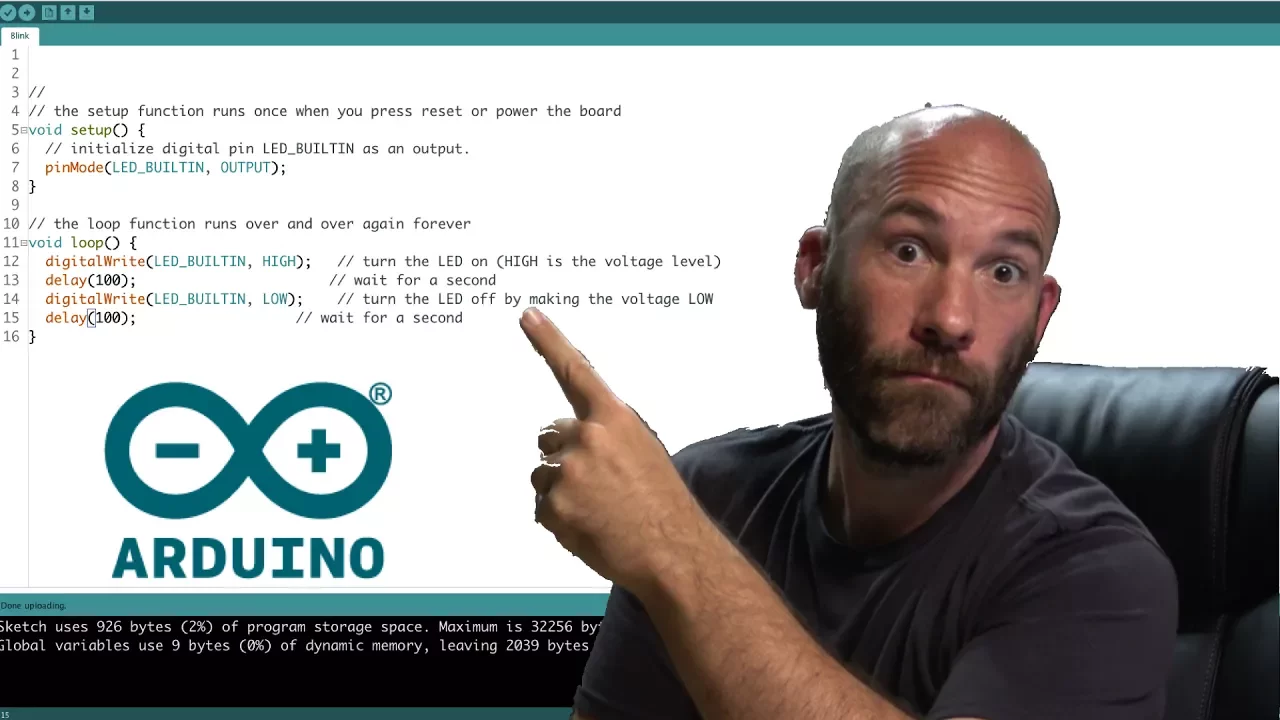
Arduino IDE Introduction
210.4K
The Arduino IDE is an integrated development environment used to write and upload code to Arduino boards, featuring essential tools like code verification, auto-formatting, serial monitoring, and serial plotting; key configurations include enabling line numbers and code folding in preferences, selecting the correct board type and COM port in the tools menu, and using the sketch menu to verify code, upload to the board, and include necessary libraries for advanced functionality.
Click to watch →

Basic concept of Arduino in Hindi | Arduino tutorials for beginners part #1
1.4M
Arduino IDE is free software available for all operating systems (Windows, Mac, Linux). Download from Arduino website by searching 'Arduino IDE' and clicking the first official option. After installation, the desktop icon launches the IDE containing: File menu (New, Open, Save), Examples menu with pre-written code templates (LED blinking, LCD interfacing, sensors), Sketch menu with Include Library for sensor commands, and Tools menu for board and port selection. For successful programming, select the correct board (Uno, Mega, Nano, Mini) and the connected serial port (e.g., COM3). The Upload button transfers programs to Arduino, enabling control of connected components like the built-in LED on pin 13.
Click to watch →
Deep Dive
Fundamental electronics concepts, specifically how potentiometers function as variable voltage dividers to adjust signal voltage.

Designing a classic transistor-VCA from scratch
162.5K
Basic volume knobs function as potentiometers configured as variable voltage dividers. In electronics, sound is represented as a swinging voltage where larger swings produce louder sounds. A voltage divider consists of two resistors in series that divide or scale down any input voltage. When the potentiometer is set to 12 o'clock position, both resistances are equal, creating a perfect 50% voltage divider that halves the input signal. Turning the potentiometer changes the resistance ratio, which determines the factor by which voltages are divided.
Click to watch →

how to use potentiometer as variable resistor and voltage divider
149.8K
A potentiometer is a three-terminal device that can function as both a variable resistor and a voltage divider; when used as a variable resistor, connecting one end terminal to a circuit point and the middle terminal to another allows resistance adjustment by rotating the knob (clockwise decreases resistance, anticlockwise increases resistance); when used as a voltage divider, connecting one outer terminal to the positive battery terminal and the other outer terminal to the negative terminal allows the middle terminal to provide an adjustable output voltage by rotating the knob, enabling precise voltage control in circuits.
Click to watch →

How Potentiometer Works - Unravel the Mysteries of How potentiometers Work!
666.8K
Potentiometers function as voltage dividers when connected with the power supply across the two end pins and the wiper connected to the output pin. As the shaft rotates, the output voltage varies proportionally to the resistance setting. The total resistance between the two outer pins remains constant, but the resistance between the left pin and center pin varies. This allows selection of any fraction of the input voltage, making potentiometers ideal for signal and control applications.
Click to watch →

DIY VCO Part 2: The simplest exponential converter
199.6K
A potentiometer functions as a variable voltage divider consisting of a resistive track with a movable wiper contact. The total resistance between the two outer connectors remains constant, while the resistance between each outer connector and the wiper varies depending on the wiper's position. By turning the knob, the voltage at the wiper can be adjusted proportionally between the input voltage and ground. This allows continuous voltage control without discrete steps.
Click to watch →
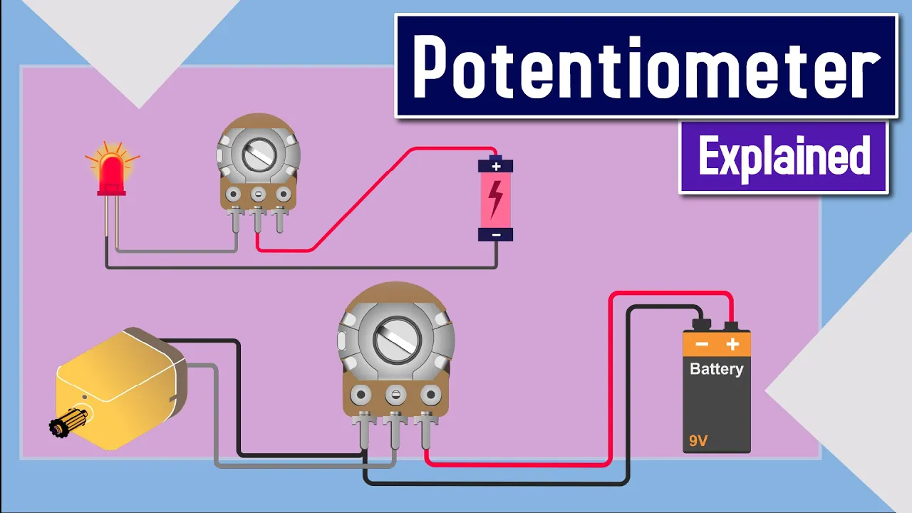
Potentiometer Explained
622.3K
A potentiometer is a three-terminal mechanically adjustable device that functions as a variable resistor or voltage divider, consisting of a resistive element with a sliding contact (wiper) that moves along it to vary resistance; when used as a variable resistor, it controls current flow (e.g., LED brightness), while as a voltage divider, it proportionally divides input voltage based on wiper position (e.g., motor speed control).
Click to watch →
Deep Dive
The difference between analog and digital signals, and how microcontrollers read varying analog inputs through an Analog-to-Digital Converter (ADC).
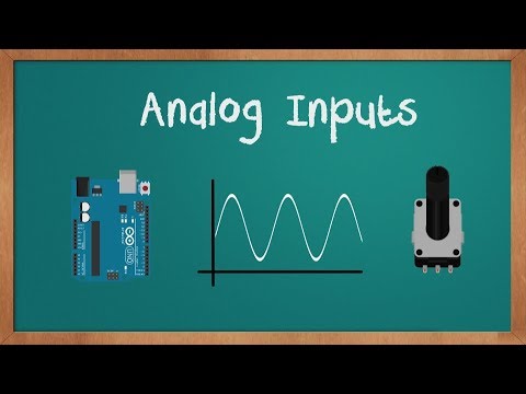
Arduino Analog Inputs
75.1K
This section covers the fundamental difference between digital and analog signals. Digital signals are binary (high/low, 0/5V or 0/3.3V), while analog signals vary continuously. The Arduino uses an ADC (Analog to Digital Converter) to read analog values from sensors like potentiometers, temperature sensors, and microphones. The ADC conversion process involves sampling (taking measurements at time intervals) and quantization (converting continuous values to discrete digital values). The Arduino has a 10-bit ADC that converts 0-5V analog signals to digital values from 0-1023, providing 1024 possible values for precise measurement.
Click to watch →
Что такое АЦП и как устроен потенциометр — управляем яркостью светодиода. Понятные уроки по Arduino
66.9K
Digital signals are binary (0 or 1) and man-made, while analog signals are continuous and found in nature. Computers like Arduino can only process digital signals, so an Analog-to-Digital Converter (ADC) is needed to translate analog signals into digital values. The ADC works by dividing the 0-5V voltage range into discrete steps (1024 steps in Arduino), similar to counting how many ladder rungs a water level has reached. This conversion allows computers to understand and process real-world analog signals like temperature or voltage.
Click to watch →
Arduino Programming Masterclass: From Basics to Libraries in 90 Mins
3.6M
Analog input pins (A0-A5) connect to the microcontroller's Analog-to-Digital Converter (ADC). Unlike digital pins that read only HIGH/LOW, analog pins read continuous voltage signals. The ADC converts these voltages into numerical values (0-1023). For example, a temperature sensor outputs varying voltage proportional to temperature, which can be read through an analog pin and converted to actual temperature values in code.
Click to watch →

Microcontroladores - O que é um Conversor AD / Entrada Analógica?
14.4K
Analog-to-Digital Converters (ADC) are microcontroller inputs that convert continuous analog signals (like temperature, light, or pressure) into discrete digital values, with the resolution (measured in bits) determining the measurement precision—higher bit resolution (e.g., 8 bits = 256 values) provides more accurate readings across the 0-5V range, while digital inputs only recognize two states (0 or 1).
Click to watch →

Clase 5 señales digitales y analógicas
105
Analog signals are continuous signals from nature (voltage, current, humidity, temperature) that vary over time and are converted to digital values (0-4095) by an ADC, while digital signals are discrete binary values (0 or 1) representing on/off states; microcontrollers like ESP32 use pull-up/pull-down resistors for digital inputs and analogRead() for reading continuous sensor values to control outputs based on threshold conditions.
Click to watch →
Deep Dive
Understanding the role of the ATmega32U4 microcontroller (found in the Arduino Leonardo) in native USB HID (Human Interface Device) emulation.
COMPREI UM NOVO PC DA XUXA PARA MODIFICAR
31K
This segment explains how microcontrollers can emulate standard computer peripherals through native USB communication. The Arduino Pro Micro utilizes an Atmega32U4 microcontroller with built-in USB Human Interface Device (HID) support, enabling direct keyboard emulation without requiring additional drivers or software installation. The system uses matrix scanning techniques where row and column pins detect key presses by monitoring circuit closures. The HID library abstracts low-level USB protocol details, allowing developers to map physical switch presses to virtual keyboard characters through simple code configuration.
Click to watch →
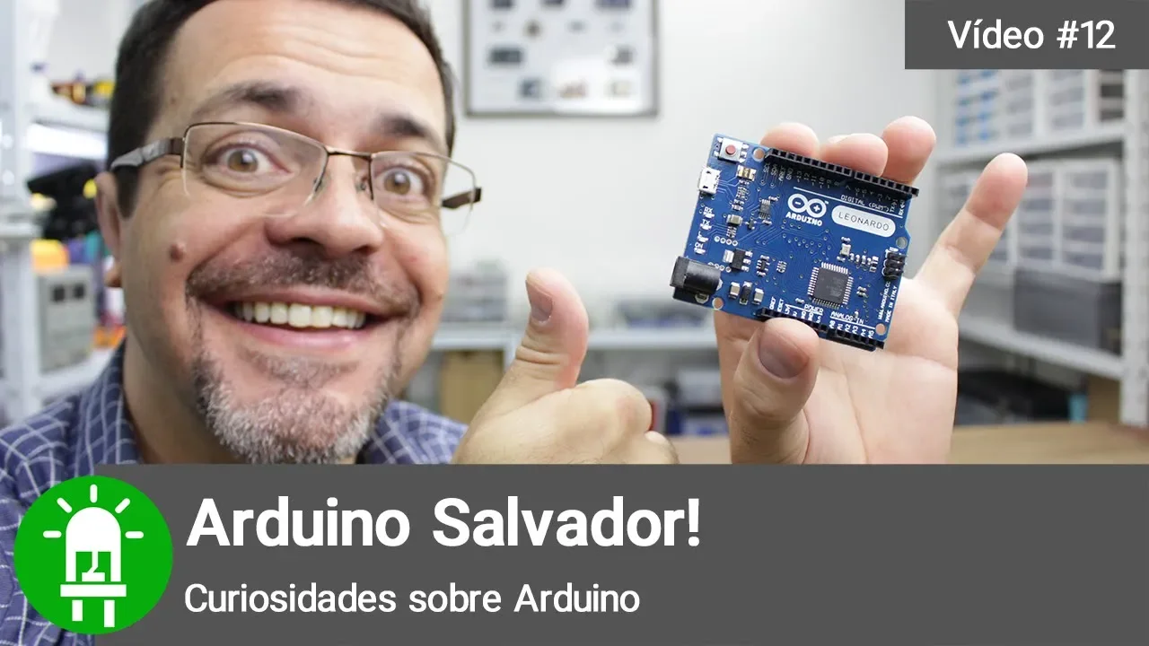
Arduino Salvador! Conheça o poder do Arduino Leonardo!
17.4K
The Arduino Leonardo can function as a USB HID (Human Interface Device) for computers, acting as a virtual keyboard or mouse to send input commands. This is achieved using the built-in Keyboard library, which allows the board to simulate key presses (press/release commands) and text input (printLN command). The Leonardo uses the ATmega 32u4 microcontroller, which enables this HID functionality. This capability allows the Arduino to automate tasks like saving files at regular intervals or typing text into applications, making it useful for creating automation utilities or pranks.
Click to watch →

Arduino como HID: crie seu próprio teclado, mouse ou joystick
10.6K
Arduino Leonardo can function as a Human Interface Device (HID), emulating keyboards, mice, or joysticks. The board contains two microcontrollers: main ATmega328P and secondary ATtiny1612. The secondary microcontroller manages USB communication, enabling the Arduino to appear as a standard USB device. The HID library (version 2.0.5) enables this functionality. The main microcontroller programs the secondary microcontroller to emulate specific devices, sending signals to computers that mimic physical input actions. To program the Arduino Leonardo, the bootloader must first be installed on the secondary microcontroller using a USB programmer like USBasp. After bootloader installation, the Arduino can be programmed directly through the Arduino IDE. If programming fails, use a metal object to briefly short the reset pins on the secondary microcontroller to enter bootloader mode.
Click to watch →
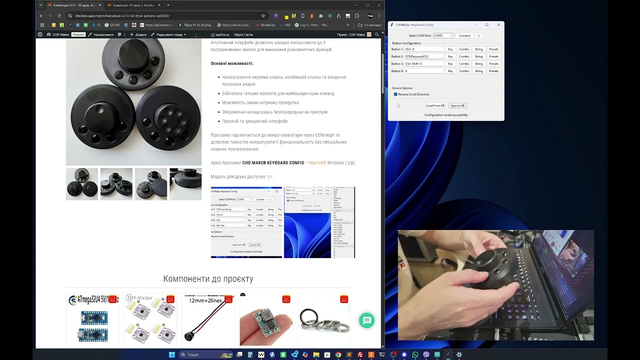
Клавіатура з енкодером на Arduino 32U4 + AS5600 та додатком під Windows (HID макропад)
180
A compact custom keyboard can be built using an ATmega32U4 microcontroller (which functions as a USB HID device) combined with an AS5600 magnetic encoder, allowing users to program button functions and encoder sensitivity through a Windows application that stores settings directly on the device.
Click to watch →
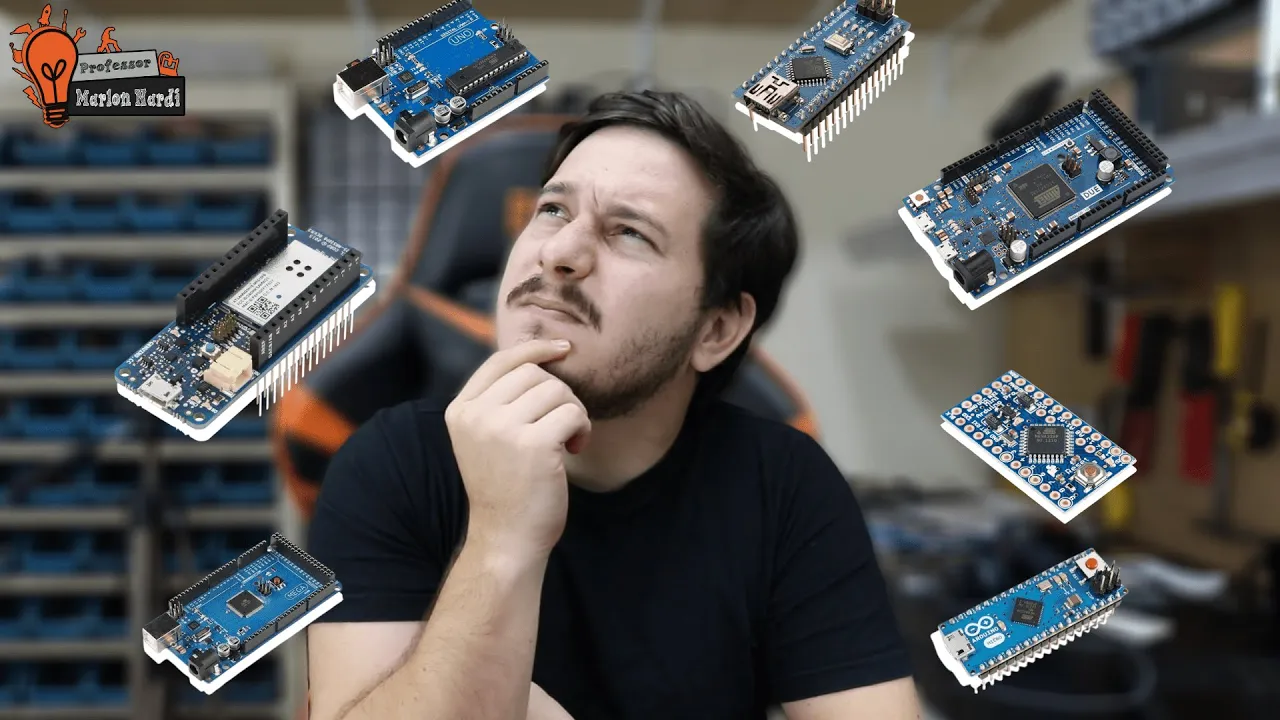
Qual Arduino comprar para o meu projeto?
18.1K
The Arduino Leonardo and Micro feature integrated USB connections directly in the microcontroller (AT Mega32U4), eliminating external USB converters. The Leonardo can emulate USB keyboards and mice, enabling projects like head-tracking interfaces for accessibility. The Micro is a smaller version of the Leonardo. Both boards use the same microcontroller architecture as the Uno but offer direct USB connectivity, making them suitable for projects requiring computer peripheral control or compact USB-based interfaces.
Click to watch →
Prerequisite Knowledge
- Concept 01Basic understanding of the Arduino platform, including how to write, modify, and upload sketches using the Arduino IDE.
- Concept 02Fundamental electronics concepts, specifically how potentiometers function as variable voltage dividers to adjust signal voltage.
- Concept 03The difference between analog and digital signals, and how microcontrollers read varying analog inputs through an Analog-to-Digital Converter (ADC).
- Concept 04Understanding the role of the ATmega32U4 microcontroller (found in the Arduino Leonardo) in native USB HID (Human Interface Device) emulation.
Subsequent Learning
- Step 01Transitioning from a solderless breadboard prototype to a permanent, durable controller using custom PCB (Printed Circuit Board) design and soldering.
- Step 02Advanced USB HID programming to customize controller reports, allowing the emulation of complex gamepads with dozens of buttons and axes.
- Step 03Designing and fabricating ergonomic physical enclosures and mechanical gimbal systems using CAD software and 3D printing.
- Step 04Implementing software-side calibration and deadzone configuration within specialized game engines or flight simulation software.
Wiring Setup
Calibration Use
Wiring Setup
0:00Playing Section
- 1
Prototype a five-axis controller using breadboard and potentiometers.
- 2
Connect power rails, analog pins, and ground to Arduino Leonardo.
- 3
Use jumper wires for solderless circuit assembly.
Contactless Sensors and Dedicated PCBs vs. Potentiometer-Breadboard DIY Designs
While a solderless breadboard and potentiometer-based Arduino build is excellent for basic learning and prototyping, it has significant limitations for practical simulation gaming. Potentiometers rely on physical friction, leading to mechanical wear, dust accumulation, sensor drift, and dead zones over time. Modern input device design strongly favors contactless technologies, such as Hall effect (magnetic) sensors or optical encoders, which offer near-infinite lifespans and superior precision. Furthermore, solderless breadboards are highly prone to loose connections under the physical stress of active gameplay; a robust controller requires soldered connections or a custom Printed Circuit Board (PCB) to ensure reliability. Lastly, standard Arduino boards feature 10-bit analog-to-digital converters (ADCs), which offer lower precision compared to dedicated USB joystick controllers or external ADCs that provide 12-bit to 16-bit resolution for much smoother control inputs.
Deep Dive
Transitioning from a solderless breadboard prototype to a permanent, durable controller using custom PCB (Printed Circuit Board) design and soldering.

From Solderless Breadboard to Soldered Circuit - Electronics with Becky Stern | Digi-Key Electronics
147.1K
To transition from a working solderless breadboard prototype to a more durable soldered circuit, first draw a circuit diagram documenting all electrical connections (not just the physical breadboard layout), then build the circuit on perfboard using plated-through holes; when switching microcontroller boards, ensure pin compatibility and update code accordingly, and finally solder all connections while verifying correctness against your diagram and prototype.
Click to watch →

Hack of the Month Club -- Project #12: From Breadboard to Circuit Board
46.6K
To transfer a working breadboard circuit to a more durable printed circuit board (PCB), first duplicate all components and install an IC socket to protect chips from soldering heat; then carefully solder each component using minimal solder to avoid bridges, ensuring clean, volcano-shaped joints; finally, connect power and audio wires using cut-off component leads, and test the new circuit against the original breadboard to verify functionality.
Click to watch →

Creating Your Own Printed Circuit Boards
103.5K
Printed circuit boards (PCBs) provide a permanent, organized solution for electronic projects that have become messy 'Rat's Nests' with wires everywhere. PCBs allow components to be soldered directly onto a board with pre-defined connection points, eliminating the need for breadboards and jumper wires. This transition from breadboard to PCB represents a significant step forward in electronics prototyping, offering durability, professional appearance, and improved reliability for electronic projects.
Click to watch →
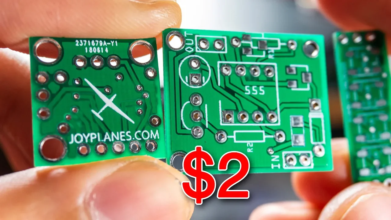
Placas PCB profesionales por $2 | JLCPCB
225.9K
When developing electronic projects, prototyping on breadboards is useful for testing circuit concepts, but once the design is verified and functional, it should be transferred to a permanent PCB (Printed Circuit Board) for professional presentation and reliability. This transition ensures the project looks professional and functions consistently.
Click to watch →
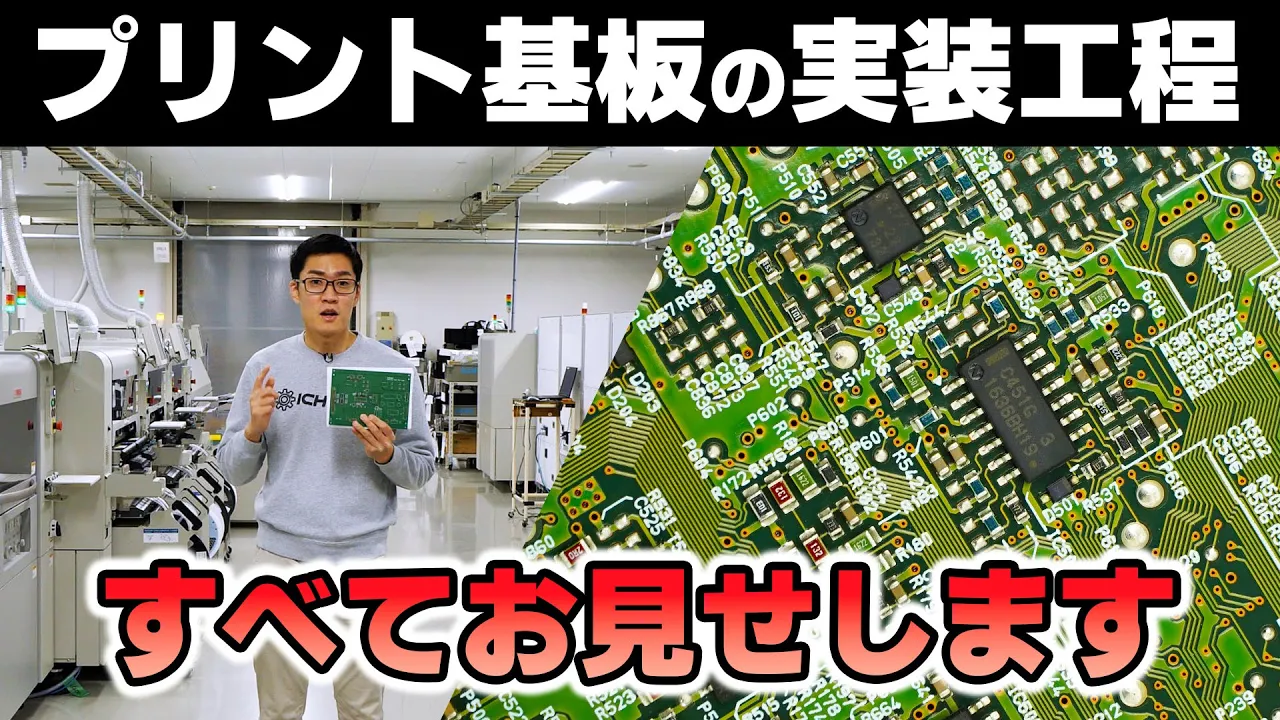
【工場見学】プリント基板実装の舞台裏に迫る! 実装・組み立て工程の全貌を大公開! 昭立電気工業
443.5K
Reflow soldering is the process of melting solder paste to create permanent electrical connections between components and PCB pads. The assembled PCB passes through a reflow oven where temperature increases gradually to melt the solder paste. The oven is typically filled with nitrogen gas to prevent oxidation of the molten solder. As the board moves through the heated zone, the solder melts and flows around component leads, creating strong mechanical and electrical bonds. After cooling, the solder solidifies in a controlled shape that ensures reliable connections.
Click to watch →
Deep Dive
Advanced USB HID programming to customize controller reports, allowing the emulation of complex gamepads with dozens of buttons and axes.
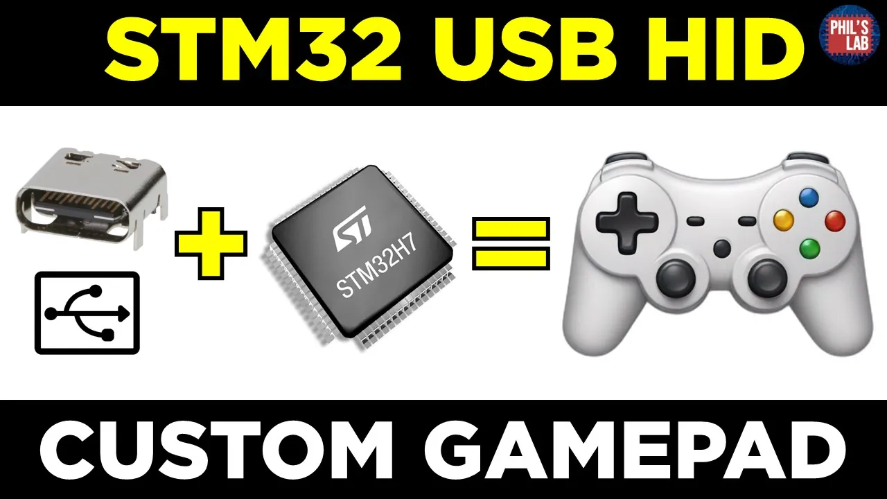
(Sponsored) STM32 USB HID Custom Joystick/Gamepad - Phil's Lab #149
33.7K
HID reports contain structured data sent from device to host, including button states and axis positions. The report structure must match the descriptor definition exactly. Joystick-specific descriptors use usage codes: X-axis (0x30), Y-axis (0x31), Z-axis (0x32), and rotation about X-axis (0x33). Four buttons require one byte (4 bits) plus padding to 8 bits. Each joystick axis uses 8 bits signed integers (-127 to +127). Data packing combines individual sensor readings into the structured format, with ADC readings (0-255 unsigned) converted to signed range by subtracting 128. Buttons are combined using bitwise operations. The packed data is sent using usbd_hid_send_report. Testing verifies OS recognition and proper axis/button mapping through Windows Control Panel and online testers.
Click to watch →
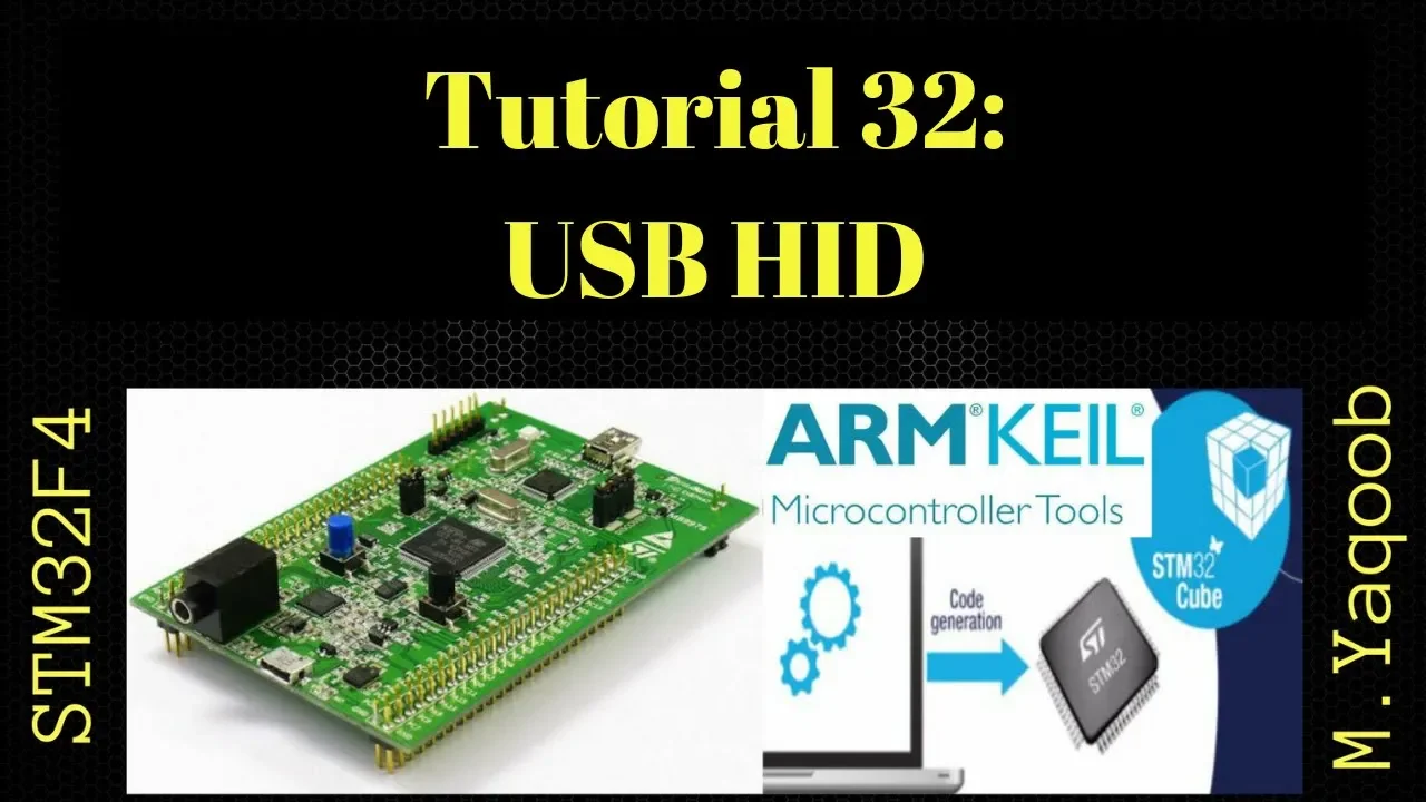
STM32F4 Discovery board - Keil 5 IDE with CubeMX: Tutorial 32 - USB HID
13.6K
This extensive section demonstrates advanced USB HID mouse implementation on STM32F4 Discovery board. It covers configuring SPI1 for LIS3DH accelerometer communication, adding the accelerometer library files to the project, initializing the accelerometer with appropriate parameters (data rate, enabled axes, full-scale range), and reading raw sensor data. The tutorial demonstrates mapping accelerometer X and Y values to mouse movement by extracting high bytes and applying them to the mouse report buffer. Practical demonstration confirms the complete system works: rolling the board moves the computer cursor, and button presses generate left-click events. The section concludes by demonstrating how to use pre-existing USB HID report descriptors from online resources, showing copying a 3-byte mouse descriptor from an online source into the USB custom HID configuration file, updating the report descriptor size parameter to match the actual descriptor length, and confirming the device functions identically despite using a different descriptor format.
Click to watch →

RISC-V WCH CH32V203C8T6. Похоже на STM32? Разбор полета
12.4K
This section demonstrates creating a custom HID (Human Interface Device) for a gamepad using the RISC-V microcontroller. The presenter explains how to configure the device descriptor in the USB configuration, including device name, description, and button mappings. The presenter shows how to implement the HID report structure and send button states to the host computer. The presenter demonstrates a working gamepad that can be connected to a computer and sends button states, showing how to create affordable custom gamepads using RISC-V microcontrollers. The presenter also demonstrates USB device communication implementation, explaining the USB device structure with input and output buffers (64 bytes each), and shows how to send data to the host and receive data from the host.
Click to watch →
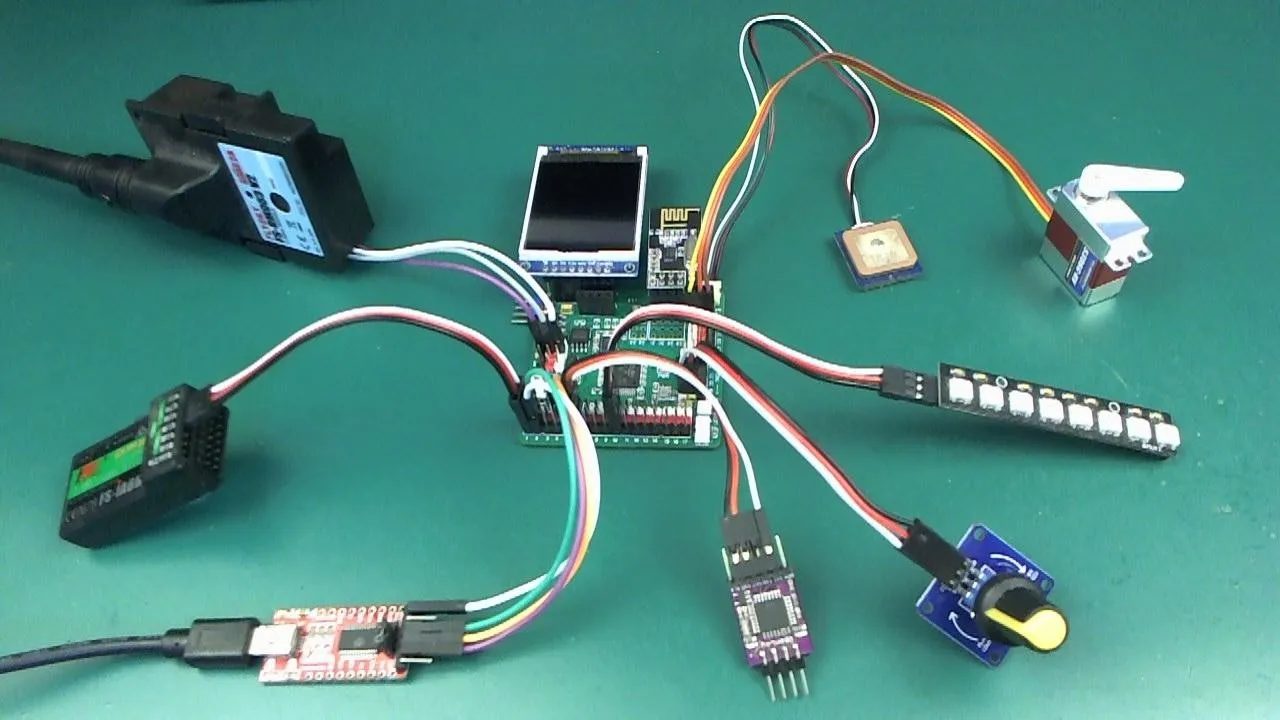
What exactly can you do with iomixer?
13.5K
The IO Mixer can emulate a USB gamepad device by setting the USB class to Virtual COM Port and Gamepad. Gamepad output nodes map RC inputs to gamepad axes and buttons. This allows using RC controllers for flight simulators or other applications requiring gamepad input. The system can map throttle, ailerons, elevator, rudder, and other controls to simulate realistic flight or vehicle operation.
Click to watch →

I made a Fight Stick using Keyboard Keys
4.1K
This segment covers the complete software architecture for creating a USB HID gamepad. Key components include USB device configuration files (tinyusb_config.h, usbdescriptors.h) that define device type and capabilities, button state management using enums for consistent interpretation, abstract interface patterns allowing interchangeable input devices, GPIO pin reading for physical button detection, and HID report structures that package button states for USB transmission. The system uses a main loop that continuously updates and sends button states to the computer, enabling real-time game input.
Click to watch →
Deep Dive
Designing and fabricating ergonomic physical enclosures and mechanical gimbal systems using CAD software and 3D printing.
DesignSpark Mechanical Training | 6 Manipulating
40.7K
This tutorial demonstrates how to manipulate 3D enclosures in DesignSpark Mechanical by adjusting cylinder diameters using the pool tool, resizing enclosure faces with multi-face selection, applying the draft tool to create angled shapes, and rounding edges using the edge control tool to achieve smooth transitions between different geometries.
Click to watch →

Le seul MacroPad que vous devez fabriquer.
1.5K
Enclosure design uses 3D CAD software like Fusion 360 to create shells and mounting features. Component libraries from GrabCAD provide 3D models for standard components. Multi-color 3D printing enables aesthetic customization using different filament colors. Web-based configuration interfaces allow users to program key mappings through a browser, communicating with the microcontroller via serial connection. The system supports multiple profiles for different keyboard layouts. Configuration is stored in EEPROM non-volatile memory, ensuring settings persist across power cycles. The software is designed for cross-platform compatibility with Windows and macOS.
Click to watch →

FreeCADと3Dプリンタで作る ジンバル iSteady X2 のアングルグリップホルダー
1.7K
This comprehensive video demonstrates the end-to-end process of designing and manufacturing an ergonomic device holder using CAD and 3D printing. The project addresses a practical problem: small devices like gimbals require unnatural wrist positions that cause fatigue and compromise functionality. The workflow includes: measuring the actual device dimensions, creating a CAD model with proper proportions and structural reinforcements, designing mounting features for versatility, and optimizing 3D printing parameters (infill, support structures, bed adhesion). The process emphasizes iterative design refinement, physical testing for strength verification, and balancing aesthetics with structural integrity. The final product enables comfortable extended use while maintaining device stability.
Click to watch →

Gehäuse für den 3D-Druck konstruieren (Tutorial)
33.6K
Two free CAD software options are available for designing 3D printed enclosures: Youcat (available for download from the video description) and 123D Design by Autodesk (also free to download). The instructor notes that 123D Design is older and no longer supported but remains sufficient for most purposes.
Click to watch →

this wooden Apple Mac Mini is cheap and really good
124.8K
Creating custom enclosures requires CAD design to translate measurements into precise technical drawings. When modifying existing products, designers must account for material differences—thicker wood requires larger dimensions than thin aluminum. 3D printing serves as both a prototyping tool and a manufacturing method, allowing rapid iteration and verification of designs before committing to final materials. The process involves creating radius gauges for measurement, designing new components when original parts don't fit, and using 3D printed jigs to ensure accurate assembly.
Click to watch →
Deep Dive
Implementing software-side calibration and deadzone configuration within specialized game engines or flight simulation software.
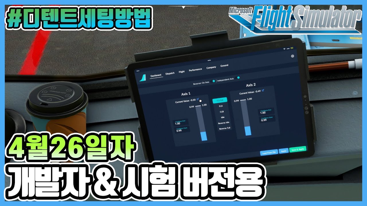
플라이트 시뮬레이터 2020│A320NX 4월 26일자 TCA쿼드런트 디텐트 설정법│개발자 & 시험 버전용 │쿠키영상있음│Microsoft Flight Simulator 2020
4.5K
Dead zone configuration determines the threshold where flight control systems recognize input. Different controls require different values: thrust reverser needs 0.05, climb/idle needs 0.02, and reverse pitch needs 0.012. These values account for joystick physical movement range. The calibration process involves creating a straight joystick line, setting dead zone values for each control surface, and verifying that the system recognizes all zones correctly without overlapping. Proper calibration ensures accurate translation of joystick movements to flight control inputs.
Click to watch →

MSFS 2024 Save Hours with these ten must-know tricks - updates in description.
112.3K
When setting up flight simulator controllers, it's essential to calibrate dead zones properly. A dead zone is a threshold that prevents constant small signals from being registered as input. If not calibrated correctly, controllers can send continuous signals that make the simulation unusable. To fix this, go to Hardware Settings and increase the dead zone value on each axis to approximately 0.1. This ensures that only intentional inputs register, eliminating unwanted drift or constant signal transmission from your controller.
Click to watch →

0.05 Controller Deadzone...
499.7K
Controller deadzone is a software feature that prevents unintended input by ignoring small, unintentional movements of controller sticks, ensuring that only deliberate inputs are registered as commands.
Click to watch →

Unreal Concepts - 2D Camera with Deadzone ( UE4 )
24.2K
A 2D camera with deadzone in Unreal Engine 4 allows the camera to remain fixed within a defined area around the player character, only activating and following the character when they move beyond specific threshold distances on the X (horizontal) and Z (vertical) axes. This is achieved by creating a custom blueprint that calculates the camera's position based on the actor's location plus or minus the deadzone values, and can be configured to lock either axis for fixed-height side-scrollers or vertical scrolling games.
Click to watch →

Unreal Engine - Deadzone Aiming Tutorial (3/3)
3.7K
This tutorial demonstrates how to implement a deadzone aiming system in Unreal Engine where the gun rotates with the character when looking left/right within a deadzone, but follows the cursor position when looking up/down outside the deadzone. The implementation involves calculating the desired gun rotation based on cursor position in world space, converting screen coordinates to world space, normalizing the direction vector, and applying the rotation while preserving pitch and roll values. The system uses a sequence node to check if cursor positions are nearly equal (indicating no horizontal movement) before updating the gun's relative rotation, preventing unwanted character rotation during vertical mouse movement.
Click to watch →
Wiring Setup
Calibration Use
Wiring Setup
0:00- 1
Prototype a five-axis controller using breadboard and potentiometers.
- 2
Connect power rails, analog pins, and ground to Arduino Leonardo.
- 3
Use jumper wires for solderless circuit assembly.
Contactless Sensors and Dedicated PCBs vs. Potentiometer-Breadboard DIY Designs
While a solderless breadboard and potentiometer-based Arduino build is excellent for basic learning and prototyping, it has significant limitations for practical simulation gaming. Potentiometers rely on physical friction, leading to mechanical wear, dust accumulation, sensor drift, and dead zones over time. Modern input device design strongly favors contactless technologies, such as Hall effect (magnetic) sensors or optical encoders, which offer near-infinite lifespans and superior precision. Furthermore, solderless breadboards are highly prone to loose connections under the physical stress of active gameplay; a robust controller requires soldered connections or a custom Printed Circuit Board (PCB) to ensure reliability. Lastly, standard Arduino boards feature 10-bit analog-to-digital converters (ADCs), which offer lower precision compared to dedicated USB joystick controllers or external ADCs that provide 12-bit to 16-bit resolution for much smoother control inputs.
Basic understanding of the Arduino platform, including how to write, modify, and upload sketches using the Arduino IDE.
Fundamental electronics concepts, specifically how potentiometers function as variable voltage dividers to adjust signal voltage.
The difference between analog and digital signals, and how microcontrollers read varying analog inputs through an Analog-to-Digital Converter (ADC).
Understanding the role of the ATmega32U4 microcontroller (found in the Arduino Leonardo) in native USB HID (Human Interface Device) emulation.
Transitioning from a solderless breadboard prototype to a permanent, durable controller using custom PCB (Printed Circuit Board) design and soldering.
Advanced USB HID programming to customize controller reports, allowing the emulation of complex gamepads with dozens of buttons and axes.
Designing and fabricating ergonomic physical enclosures and mechanical gimbal systems using CAD software and 3D printing.
Implementing software-side calibration and deadzone configuration within specialized game engines or flight simulation software.
164.8K views2.9Klikes3:00@amstudioprojectsOriginal Release: 2018-04-25
to set up the five access controller we will need a breadboard jumper wires 510k potentiometers and an Arduino Leonardo bread boards are great for solderless prototyping of electronic projects to use these boards we need to understand the basic layout at the top and bottom we have the power rails each row is joined along the back horizontally with a metal strip the middle section is separated by a center channel and then these are connected vertically at the back with metal strips we can also use small versions of the boards for smaller electronic test projects start with place the potentiometers into one side of the breadboard then the first wired connection plugs directly behind the first terminal of the potentiometer and then into the positive power rail on the breadboard the second connection is the center terminal to the i/o analog input on the Arduino the third connection is the last terminal of the potentiometer to the negative rail on the breadboard repeat this process with the remaining four potentiometers with the positive and negative on each side and the center pin to the remaining analog inputs a 1 through 2 a 4 with the final connections plug in a jumper cable from the positive rail to the five volt on the Arduino board and a ground jumper wire from the Arduino to the negative rail on the breadboard to complete the wiring with all the connections complete plug in a USB cable from the board to a PC installing the sketch also requires the joystick library to be pre-installed open the five axis sketch in the Arduino software then select the Leonardo board and select the correct communication port verify then upload the sketch to the board once the upload is complete open the game controller properties and calibrate the axis by turning each of the knobs now we have completed a prototype analog controller for five axis the analog axis can be adapted to control your next project these include controlling throttle brake and clutch pedals a handbrake hand controls on a wheel or for use with flight Sims [Music] [Music]
Up Next

3:39
Building a Cost-Effective ROV Video System with a 700TVL Camera
@NickSopwith
3.2K views•2013-11-17

12:54
Triumph of Orthodoxy Icon: Byzantine Art & History Explained
@BenCallan
2.1K views•2024-08-06

9:49
FastAPI vs Flask vs Django: Choosing the Right Python Web Framework
@TechWithTim
302.5K views•2024-05-26

1:42
Game of Thrones Opening Credits: A Cinematic Analysis
@gameofthrones
46.3M views•2011-04-18
Related Study Plans & Knowledge Roadmaps
Structured learning paths in General & Interdisciplinary Studies
general-studies
Elevator Engineering: History, Physics & Cities
01From Hoists to Safety Brakes: The Dawn of Vertical Lift
02Hydraulic vs. Traction: The Engineering Physics of Elevators
03Modern Speed, Safety, and Algorithms
+ 2 more learning modules
12h5 modules
Explore Roadmap
general-studies
Rubber: Material Science, History & Geopolitics
01Origins of Natural Rubber & Mesoamerican History
02The Chemistry of Natural Rubber & Vulcanization
03The Geopolitics of the Rubber Boom & Colonization
+ 2 more learning modules
12h5 modules
Explore Roadmap
general-studies
Containerization: Evolution, Logistics & Trade
01Ancient Trade & Bulk Cargo: Amphorae to Barrels
02The Industrial Revolution & Cardboard Packaging
03The Containerization Revolution: Malcom McLean
+ 2 more learning modules
12h5 modules
Explore Roadmap
general-studies
Textile Tech: Evolution, Labor & Global Impact
01Pre-Industrial Textiles: Handloom & Cottage Industry
02Mechanization: The Spinning Jenny to the Power Loom
03The Factory System & Global Labor Transformation
+ 2 more learning modules
10h5 modules
Explore Roadmap