
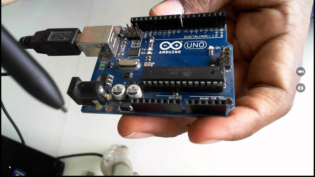


![[ARDUINO] 전자회로 기초](https://i.ytimg.com/vi_webp/VtBB5u85KCw/maxresdefault.webp)






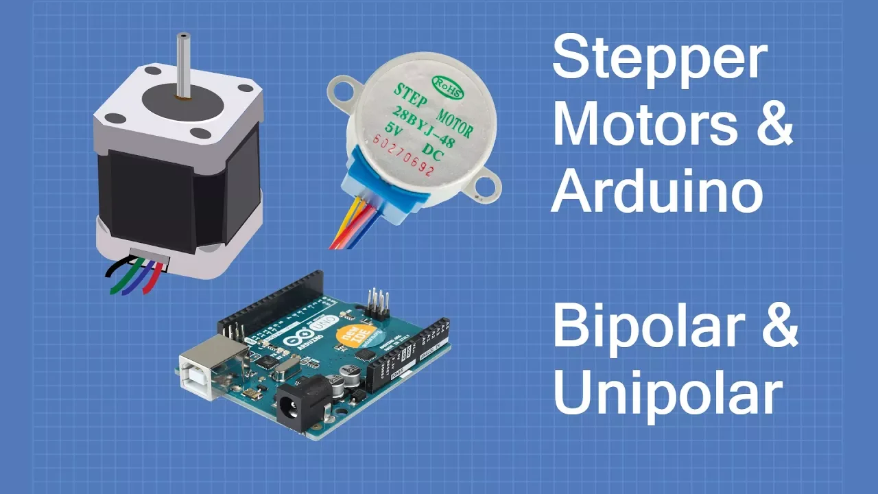


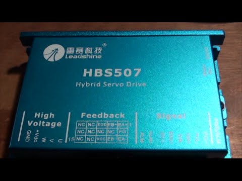
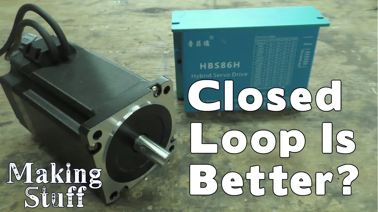


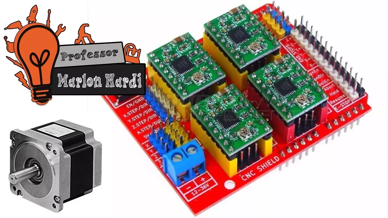

The TB6600 is a bipolar stepper motor driver capable of controlling larger two-phase stepper motors (like NEMA 17/23) with operating voltages from 9-42V DC and currents up to 3.5A, offering microstep resolutions up to 1/32 compared to the TB6560's 1/16; it connects to Arduino via pulse, direction, and enable pins, with the motor coils connected to the driver's output terminals, and requires proper DIP switch configuration for microstep mode and current setting, where the number of steps per revolution varies (200 steps for full step, 400 for half step, 800 for quarter step) to achieve one complete motor rotation.
TB6600 Stepper Motor Driver with Arduino: NEMA 17/23 Guide
Added:Basic Arduino programming and the Integrated Development Environment (IDE), including uploading sketches, defining variables, and managing digital I/O pins.
Fundamental electronics concepts such as voltage, current, resistance, Ohm's Law, and the importance of establishing a common ground in multi-voltage circuits.
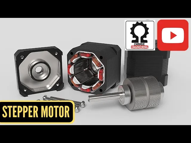
The operational theory of stepper motors, including how electromagnetic phases are sequentially energized to produce precise rotational steps.
The core purpose of a motor driver, specifically why microcontrollers cannot directly power high-current inductive loads like NEMA 17 or 23 motors.
Implementing advanced stepper motor control libraries like AccelStepper to achieve smooth acceleration, deceleration, and non-blocking multi-axis control.
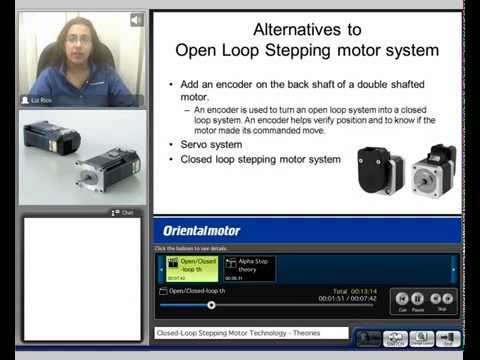
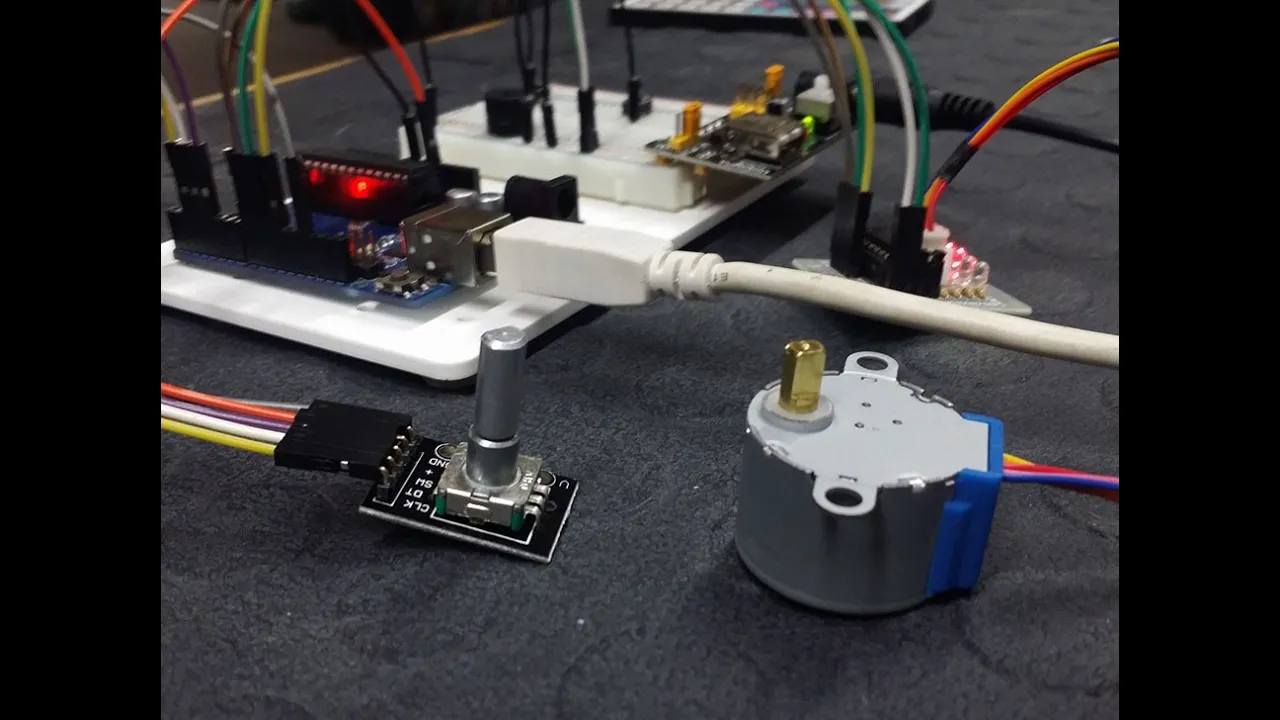
Designing and calibrating closed-loop stepper systems using rotary encoders to monitor shaft position and prevent skipped steps under heavy loads.
Deploying GRBL firmware or equivalent G-code parsers on Arduino to convert CNC commands into real-time step and direction signals for the TB6600.
Thermal management and power system optimization, including calculating continuous current limits, choosing appropriate power supplies, and designing cooling systems for the driver.
192.8K views1.7Klikes10:02Original Release: 2022-02-02
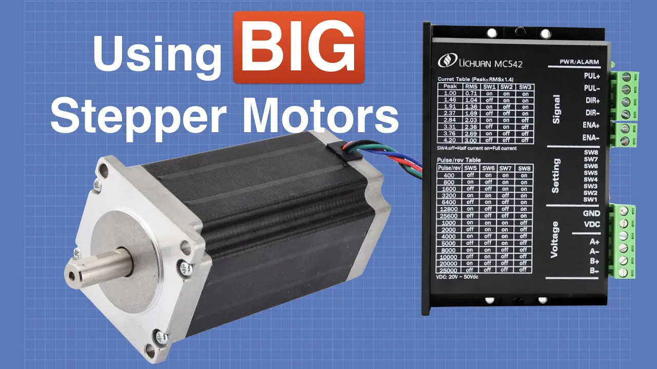
hello everyone today i would like to talk about the tb 6600 stepper motor driver which is this one here so this one is used in controlling larger two-phase bipolar stepper motors for example the nema 17 and 23 motors that are used in 3d printers cnc machines and also in a number of robotics so normally when you go to purchase this motor driver you're also going to come across another water driver which is this one here this other one is the tb6560 i've done a separate tutorial on how to use this motor driver with arduino so by this motor driver the connection with arduino and even the coding is the same but they have some differences just as you can see here the appearance is different and even some of the performance is different for example the operating voltage of tb6600 is from 9 to 42 volts dc well for this one is from 10 to 35 versus dc this one uses 3.5 amps the current or this one uses for amp speed current even the microstep resolution is different this one has a resolution of up to 1 out of 32 or this one only stops at 1 out of 16. the clock frequency of this one is 200 kilohertz or this one is 15 kilohertz even appearance here you see this one is quite well built the electronics is covered and even has a larger heat sink compared to this one here so in most cases if you have projects that need more accuracy and more current then the tb6600 stepper motor driver is preferred to the tb6560 stepper motor driver you can visit the links in the description below so that you can have further look at the major differences and how these two water drivers work with arduino but for today i'm mainly going to concentrate on the tb-6600 stepper motor driver so as you can see this motor driver has the stables here the upper table this one represents the microstrip resolution and the other one is the running current for driving the motors these tables will give you how you have to adjust the pins that yeah the idea if it pins as you can see these vip pins are adjusted depending on the tables that are drawn on top here so depending on the microstep mode that you want to use and the amount of current that is being supplied to the motors you had just here for example here these these 68 switches have been adjusted right here this is in full step mode and this is one amp of current supply whenever i want to make adjustments you can just make reference here and adjust according to how you're going to be setting up your motor driver and the motor that you're going to be using and the current supply so now let me have a look at how the tb6600 stepper motor driver is connected to arduino and also a bipolar stepper motor so this is how we are going to connect our tb 6600 stepper motor driver to arduino onto a bipolar stepper motor so this side of the driver is going to be connected to our arduino board and what we do we connect to the negative terminals for the pulse direction on the enable pins to arduino ground then the the power is positive is going to be connected to arduino pin five the direction positive is going to be connected to pin two and the neighbor positive is going to be connected to pin h you can leave the neighbor pins floating in others i mean if they're not connected to anything because they are by default law meaning that the output pins are enabled but i always prefer connecting them to i do not ground and the positive to an arduino digital pin so that i can find it easier in case i need to disable the motor using the software program and will be easier this other half of the driver is where you connect the power supply and also the connection to the stepper motor so on our power supply we have the ground on the vcc here connect a dc voltage from 9 volts to 42 volts in my case i'm using 12 volts then these four terminals here for connecting the corresponding chords of the bipolar stepper motor so we are going to have the first pair of coils it's going to be connected to a plus and a minus and then the second pair of chords is going to be connected to b plus and b minus so before connecting the wires you have to know which of the wires belong to the same coil of the stepper motor in case your motor has not specified the wires belonging to each of the coils you can use a simple trick here to know which which wires belong to the same coil of the stepper motor so let me show you how you can test that so if you're using this kind of motor like the one i'm using normally there's no need of checking which one has belonged to the same coil because the wires are arranged in order so you'll find that the red and blue eyes not the same coil and even the green and black wires you don't have the same coil but if your motor does not specify which wires belong to each coil then the trick is simple so simply just connect the bear for example if i connect the blue and red wires here and i turn this shaft here you you shall have there will be a lot of resistance in down in the shaft so when you feel out of resistance that means these two wires belong to the same coil if you try the same with the wires from the different coil for example if i connect blue and green then connect blank green so if i connect a blank green and then i turn the shaft the motor shaft will move freely in otherwise there will be less resistance in turning the shaft so that's how you simply identify which of these wire belongs to the same coil just connect the wires the ones which gives you resistance entering the shaft meaning those two pairs of those two wires belong to the same coil so after connecting the tb6600 stepper motor driver to arduino under a bipolar stepper motor you can check out the kind of code that you're going to be using to run this motor this is the code you're going to be using to run our stepper motor using the tb6600 stepper motor driver first of all you have to declare the pins connected to the arduino board so we declare the step pin or the pulse pin the direction pin and the enable pin with the corresponding pins where they are connected then the setup section we simply initiate these pins as output and the enable pin is also declared as low or is set as low so that we can be able to enable the driver in the loop section it's very determining the number of steps that the motor is going to be taking to complete the revolution so for example here we're going to be using these four lines of code to send a pulse to the step pin so that you can be able to have one macro step then the for loop repeats these four lines for a given number of times for example in this case this follow-up is going to repeat these four lines 800 times so it depends on the microstep resolution for your motor that you have set the motor driver if the motor drive has been set in a quarter step microstep resolution then it means that 800 steps will result into one revolution so this code will be able to turn the motor one revolution the driver is in a quarter step mode if it is in half step mode every revolution needs 200 steps so it means this cord is going to turn the motor through time is in half step mode then in full step mode it will be turning for times because in full step mode one revolution is 200 steps we have used this direction pin to determine the direction of rotation of the motor and that is done by changing the state of the spin if the pin is high the motor will be rotating in one direction and if you turn it low then it changes the direction of rotation but we have used the delay microseconds function to control the speed of rotation so the shorter the delay here the higher the frequency and therefore the faster the motor will be rotating so let's upload this code to our arduino and then we'll see how the motor is going to be moving with the tb6600 stepper motor driver so i have now uploaded the code into the arduino and also set my tb660 stepper motor driver quarter step mode where i want to see what will happen if i'm using 800 steps per revolution so first of all let me first turn on the motor driver so when the motor driver is switched on you see a blue light here there's a light indicating the power supply is on and after that we can put on our turn on the arduino and then we see what will happen so you can see now the motor is turning one revolution in one direction and then changes to another direction that's because it is now in a quarter step mode meaning that it will only turn on revolution because i've set 800 steps per revolution now let me set it to a half step mode and let me see what will happen the rotation to change the microstep resolution we need to adjust these dip pins on the side but we should never adjust the vip pins when the driver is on so first of all you need to first switch off the driver and then insert the dip switches otherwise may end up damaging your motor driver so i have now adjusted the dip switches to a half step mode so let me turn on the arduino and then you see how the motor is going to move you're still using the same chord and now as you can see those are using half step mode the motor bit turning for revolutions in one direction and then two revolutions in the other direction this is because now the motor is now rotating 400 steps per revolution and in a chord we are using 800 steps so finally let me put it in full step mode and then we see also what happens there so i've now adjusted to full step mode let me put on the arduino so there you can see the motor is now moving for revolutions in one direction and then turns to four versions in the other direction but the code is still the same so that is the simple working of this tb6600 stepper motor driver with arduino you can check the description below for the code schematics and even fat explanation of how this motor driver works with arduino and even further coding even including the libraries for arduino hope you've learned something new today don't forget to subscribe to my channel and watch my other tutorials thanks for watching
Up Next

48:11
Scotch Yoke Mechanism Design Tutorial in Fusion 360
@learningpower9437
1.6K views•2022-05-28

12:54
Triumph of Orthodoxy Icon: Byzantine Art & History Explained
@BenCallan
2.1K views•2024-08-06

9:49
FastAPI vs Flask vs Django: Choosing the Right Python Web Framework
@TechWithTim
302.5K views•2024-05-26

1:42
Game of Thrones Opening Credits: A Cinematic Analysis
@gameofthrones
46.3M views•2011-04-18
Related Study Plans & Knowledge Roadmaps
Structured learning paths in General & Interdisciplinary Studies
general-studies
Elevator Engineering: History, Physics & Cities
01From Hoists to Safety Brakes: The Dawn of Vertical Lift
02Hydraulic vs. Traction: The Engineering Physics of Elevators
03Modern Speed, Safety, and Algorithms
+ 2 more learning modules
12h5 modules
Explore Roadmap
general-studies
Rubber: Material Science, History & Geopolitics
01Origins of Natural Rubber & Mesoamerican History
02The Chemistry of Natural Rubber & Vulcanization
03The Geopolitics of the Rubber Boom & Colonization
+ 2 more learning modules
12h5 modules
Explore Roadmap
general-studies
Containerization: Evolution, Logistics & Trade
01Ancient Trade & Bulk Cargo: Amphorae to Barrels
02The Industrial Revolution & Cardboard Packaging
03The Containerization Revolution: Malcom McLean
+ 2 more learning modules
12h5 modules
Explore Roadmap
general-studies
Textile Tech: Evolution, Labor & Global Impact
01Pre-Industrial Textiles: Handloom & Cottage Industry
02Mechanization: The Spinning Jenny to the Power Loom
03The Factory System & Global Labor Transformation
+ 2 more learning modules
10h5 modules
Explore Roadmap