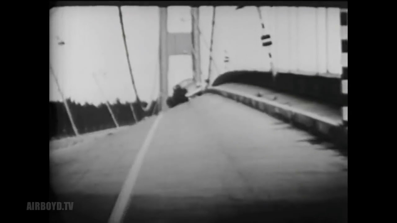
The Tacoma Narrows Bridge, nicknamed 'Galloping Gertie,' collapsed on November 7, 1940, due to aerodynamic flutter caused by wind-induced torsional oscillations; this catastrophic failure fundamentally changed bridge engineering design principles by demonstrating that suspension bridges must account for aerodynamic stability alongside structural strength, leading to safer modern suspension bridge designs worldwide.
Galloping Gertie: Tacoma Narrows Bridge Collapse Analysis (1940)
Added:Deep Dive
Basic physics of oscillations, including concepts of natural frequency, amplitude, and mechanical resonance.

Resonance and Natural Frequency Explained
125.8K
Natural frequency is the frequency at which an oscillating object vibrates after an initial disturbance, while resonance occurs when the driving frequency of an external force matches the object's natural frequency, causing the amplitude of oscillation to increase dramatically to a maximum value before decreasing again.
Click to watch →

SSLC Physics | Sounds Waves | Complete Textbook line by line | Alex Sir
185.9K
Oscillatory motion is periodic back-and-forth movement around an equilibrium position. A complete oscillation requires returning to the starting position AND in the same direction. Amplitude is maximum displacement from equilibrium, measured in meters. Time period is time for one oscillation (seconds). Frequency is oscillations per second (Hz). They are reciprocals: f = 1/T. As pendulum length increases, time period increases and frequency decreases. Natural frequency depends on object's length, size, elasticity, and material. Forced vibration occurs when external force frequency differs from natural frequency, reducing amplitude. Resonance occurs when external force frequency matches natural frequency, causing dramatic amplitude increase. Applications include tuning forks on tables, musical instruments, and stethoscopes.
Click to watch →

Oscillations In One Shot | Class 12 Physics | Maharashtra HSC Board | MHT CET Physics | NEET
221.5K
Natural frequency is the frequency at which a system oscillates without external driving force, determined by its physical parameters. For a simple pendulum, natural frequency is f = (1/2π)√(g/L). Resonance occurs when driving frequency equals natural frequency, resulting in maximum amplitude because the driving force continuously adds energy in phase with motion. At resonance, the system absorbs maximum energy from the driving force. This phenomenon is observed in musical instruments, bridges, and many other systems. The resonance frequency equals the natural frequency of the system.
Click to watch →

CBSE Class 12 Physics || Alternating Current || Full Chapter || By Shiksha House
136.8K
Resonance is a phenomenon observed in systems that tend to oscillate at some fixed frequency called the natural frequency. When such a system oscillates at its natural frequency under the influence of an external periodic force, the amplitude of oscillations becomes noticeably larger than at other frequencies. For example, when pendulum P oscillates, pendulums with equal length (same natural frequency) oscillate with increasing amplitude due to resonance, while others remain unaffected.
Click to watch →

Lab Assistant Physics | Rajasthan Lab Assistant Live Class | Oscillations | By Sameer Sir
29.3K
Resonance occurs when driving frequency equals natural frequency, causing maximum amplitude. Natural frequency is the frequency at which an object oscillates when displaced and released without external force. Each object has its own natural frequency determined by its physical properties. Practical applications include musical instruments, tuning forks, and avoiding resonance in bridges (soldiers not marching in step). The amplitude becomes very large at resonance.
Click to watch →
Deep Dive
The fundamental structural components and load-bearing mechanics of suspension bridges, specifically tension and compression.
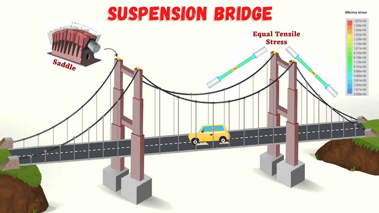
Suspension Bridge | How Do Suspension Bridges Work | Design Factors of Suspension Bridges | Lec -08
27.8K
A suspension bridge consists of a deck hung below main cables by vertical suspenders, with cables suspended between towers and anchored at both ends. Main cables carry loads through tension, while towers transfer axial compressive forces to foundations. Cable bands connect suspenders to cables, restricting longitudinal slippage. Main cables comprise thousands of steel wires spun together, protected by polyethylene sheathing and epoxy resin. Saddles guide cables through towers, transferring loads vertically. Anchorages resist tensile forces preventing tower bending. Wind effects cause dangerous oscillations in long-span bridges, solved by adding truss or girder stiffening elements for aerodynamic stability.
Click to watch →

Golden Gate Bridge: The Structure that Defined an Era | FD Engineering
554.1K
A suspension bridge is a complex engineering structure that combines solid functionality with lasting strength and architectural splendor. The basic design consists of anchorages on either shore that hold cables draped over towers, which suspend the roadway. The structure relies on two fundamental forces: tension (horizontal force transferred into anchorages) and compression (vertical force transferred into towers and dissipated into the Earth). This allows bridges to span great distances with minimum structural weight.
Click to watch →

AE 104/CIVE 104 Suspension Bridges Practice
590
A suspension bridge comprises foundations, piers, anchorages, towers, main cables, and suspenders. Cables and suspenders undergo tension to support the deck, while anchorages remain in tension to maintain the main cable. Towers and foundations undergo compression as they resist tension forces from cables and suspenders. The angle between the main cable and horizontal is inversely related to tension force—smaller angles require larger tension forces to maintain equilibrium. This relationship follows trigonometric principles where x and y components depend on sine and cosine of the angle.
Click to watch →

3-2-1 Contact- 227: Shapes & Gravity
1.7K
In suspension bridges, the towers experience compression (pushed downward) while the cables experience tension (pulled). The extra cable extending beyond the towers provides anchorage that keeps everything steady. Without this anchorage, the towers would fall inward and the roadway wouldn't be held up.
Click to watch →

Puente Tony
167
A suspension bridge consists of three main structural components: towers and pillars that provide compression support, cables that handle tension forces, and a deck (tablero) that carries the load; reinforcement structures like crossed wooden beams can increase the bridge's load-bearing capacity beyond basic design specifications.
Click to watch →
Deep Dive
Introductory aerodynamics, particularly how fluid flow (wind) generates lift, drag, and vortex shedding forces on structures.

Hormigón Armado II - Viento / Teoría Asincrónica - Clase 2 (Parte 1)
316
Real viscous fluids separate from surfaces under adverse pressure gradients, unlike ideal inviscid flow. Behind cylinders, alternating Karman vortices form periodically, creating lift forces on structures. Lift force varies with velocity in a campaniform pattern, reaching maximum at critical velocity calculable via Strouhal number. Drag force increases parabolically with velocity. These vortex-induced forces cause dynamic structural loading requiring special consideration in wind-resistant design.
Click to watch →

Hormigón Armado II - Viento / Teoría Asincrónica - Clase 4 (Parte 1)
216
Wind turbulence produces dynamic excitation on structures, with response depending on shape, materials, frequency, and damping. Key phenomena include Karman vortex formation, where alternating vortex shedding creates lateral forces. When vortex shedding frequency matches structural natural frequency, resonance occurs. Drag force increases parabolically with wind speed, while lift force follows a bell-shaped curve. Reynolds number determines shedding regimes: Re < 10^5 produces alternating vortices, Re > 35 produces turbulent shedding. Solutions include adding fins, texturing surfaces, or installing helical fins to prevent vortex formation and resonance.
Click to watch →
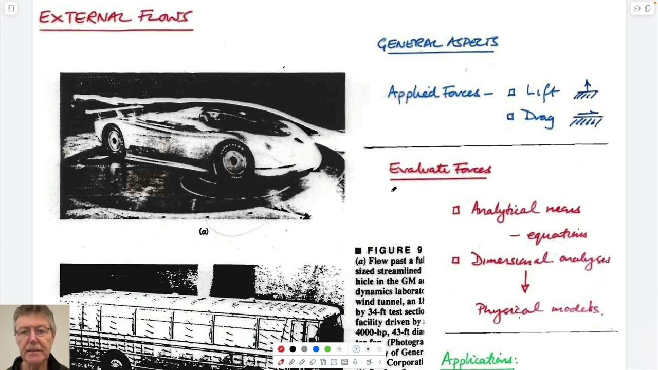
12:2 External Flows - Drag and Lift, Viscous and Pressure Drag/Lift, Dependence on Re
117
This comprehensive section introduces aerodynamics through historical failures and fundamental principles. The Tacoma Narrows Bridge collapse demonstrates catastrophic resonance when wind-induced vortex shedding matches structural natural frequencies. High-lift devices on aircraft wings (leading-edge flaps, slats) show how engineers manipulate geometry to increase lift during low-speed operations. Drag opposes motion while lift acts perpendicular to flow, with applications from vehicle efficiency to tire traction. The section explains that these forces decompose into pressure (normal to surfaces) and viscous shear (parallel to surfaces) components, resolved using trigonometric relationships. These foundational concepts establish why understanding fluid-structure interactions is critical for engineering design across transportation and infrastructure applications.
Click to watch →

Fundamentals of Aerodynamics . Introduction . Introduction to Aerodynamics
12.6K
Aerodynamics is the branch of fluid mechanics concerned with predicting and controlling the forces and moments acting on objects moving through the atmosphere; these forces include pressure forces (which create buoyancy in stationary objects and contribute to aerodynamic forces when moving) and shear stress (friction between fluid and object surfaces), which together generate the total aerodynamic force that can be resolved into lift (perpendicular to free stream velocity) and drag (parallel to free stream velocity); aircraft are classified into aerostats (which offset weight mainly through buoyant forces like dirigibles and hot air balloons) and aerodynes (which use aerodynamic forces to offset weight, further divided into fixed-wing aircraft and rotorcraft).
Click to watch →
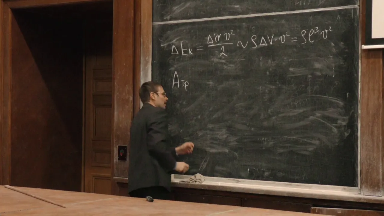
Якута А. А. - Механика - 24. Обтекание тел. Лобовое сопротивление. Подъёмная сила
6.1K
Drag force on bodies in fluid flow arises from momentum conservation. Fluid entering the body region has higher momentum than fluid leaving due to vortex shedding. The difference in momentum flux must be balanced by a force exerted by the body on the fluid, which equals the drag force. Vortex shedding creates alternating low-pressure regions behind bluff bodies, forming Kármán vortex streets. This phenomenon causes oscillating forces and contributes significantly to drag.
Click to watch →
Deep Dive
The difference between translational motion (vertical/lateral movement) and torsional motion (twisting) in engineering mechanics.

प्रयोगशाला परिचारक || भौतिक विज्ञान क्लास 2 || गति के प्रकार भाग 1 || निशुल्क by B.K.PATEL SIR
47.1K
Translational Motion (स्थानांतरण गति) is the simplest type of motion where an object moves in a straight line. It can occur in any direction - horizontal, vertical, or at any angle - as long as the motion follows a straight path. Rotational Motion (घूर्णन गति) occurs when an object spins or rotates around a fixed axis. Examples include the Earth rotating on its axis, a spinning top, a ceiling fan, or a globe. The Earth exhibits both rotational motion (spinning on its axis) and circular motion (orbiting around the Sun).
Click to watch →

مجموعة كبيرة من الفروض المقترحة للفصل الثاني ثانية متوسط
25.1K
Translational motion occurs when all points of a body move along parallel and identical paths, including rectilinear (straight) and curvilinear (curved) types. Rotational motion occurs when a body rotates around an axis that belongs to the body itself, with at least one point (the center of rotation) remaining stationary while others move in circular paths. The key distinction is that translational motion has an external axis of rotation, while rotational motion has an internal axis.
Click to watch →
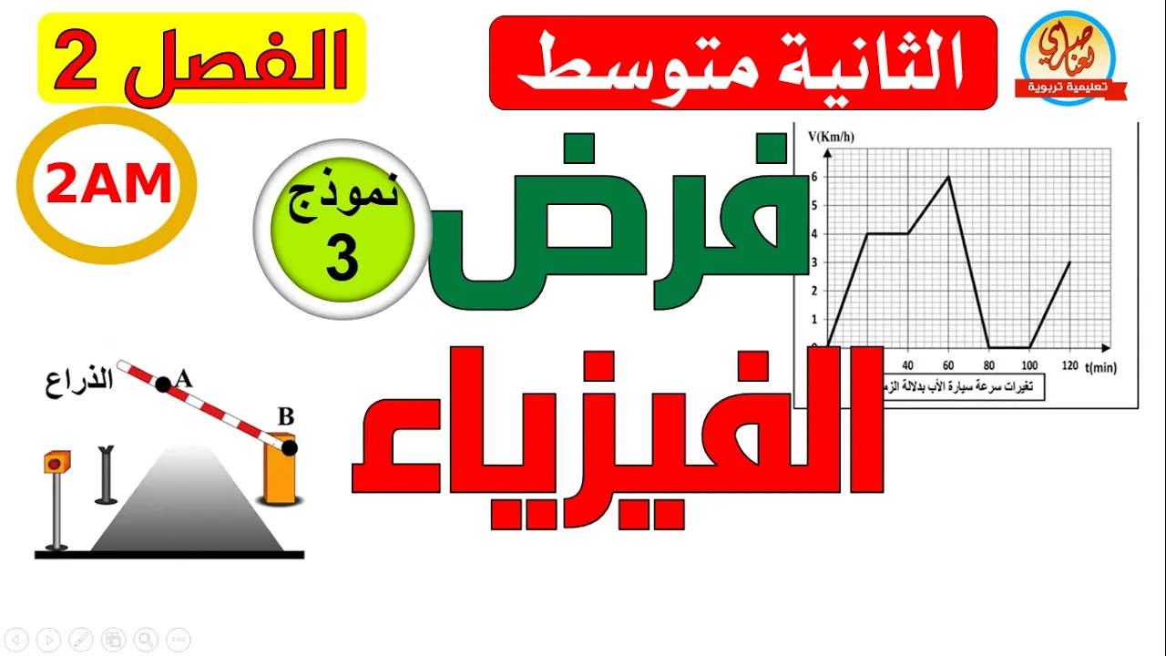
فرض الفيزياء للسنة الثانية متوسط للفصل الثاني
269K
Motion is relative to a chosen reference frame. A point can be stationary relative to one frame while moving relative to another. Translational motion occurs when all points trace parallel, identical paths in the same direction. Rotational motion occurs when all points trace circular paths around a fixed axis, with the axis remaining stationary. The key distinction is that in translational motion, all points move identically, while in rotational motion, points at different distances from the axis trace circles of different radii.
Click to watch →

Top Most Important|5 Marks|Public Exam Preparation|Physics 11|Stateboard|Tamil|Muruga MP#murugamp
74K
Comparison between translational motion (linear movement) and rotational motion (spinning around an axis). Key differences include how forces, acceleration, and energy are applied in each type of motion.
Click to watch →

فرض الفصل الثاني في الفيزياء للسنة الثانية متوسط النموذج الثالث
1.2M
The fundamental difference between translational motion and rotational motion lies in the paths traced by the points of the body. In translational motion, all points of the body trace parallel and identical paths. In rotational motion, different points of the body trace circular paths of different sizes, and these paths are not identical to each other. This distinction is crucial for classifying the type of motion a body is undergoing.
Click to watch →
Prerequisite Knowledge
- Concept 01Basic physics of oscillations, including concepts of natural frequency, amplitude, and mechanical resonance.
- Concept 02The fundamental structural components and load-bearing mechanics of suspension bridges, specifically tension and compression.
- Concept 03Introductory aerodynamics, particularly how fluid flow (wind) generates lift, drag, and vortex shedding forces on structures.
- Concept 04The difference between translational motion (vertical/lateral movement) and torsional motion (twisting) in engineering mechanics.
Subsequent Learning
- Step 01The theory of aeroelasticity and the mathematical modeling of self-excited aerodynamic flutter.
- Step 02Modern bridge aerodynamics, including the use of open truss designs, aerodynamic deck fairings, and wind deflectors.
- Step 03The integration of physical wind tunnel testing and Computational Fluid Dynamics (CFD) in modern structural design.
- Step 04Case studies of post-1940 suspension bridges (such as the Severn Bridge or the Mackinac Bridge) that implemented lessons from the collapse.
- Step 05The evolution of structural engineering building codes and safety factors regarding dynamic wind loading.
Music Start
Vocal Mix
Final Crescendo
Music Start
0:05Playing Section
- 1
Opening melody begins with rhythmic beats.
- 2
Audience atmosphere sets positive engagement tone.
- 3
Initial sounds cue the main event soon.
Aeroelastic Flutter vs. Classical Resonance Misconception
While many physics textbooks historically attributed the 1940 Tacoma Narrows Bridge collapse to 'classical resonance'—where periodic wind gusts matched the bridge's natural frequency—modern engineering and physics consensus rejects this explanation. Research, notably by Billah and Scanlan (1991), demonstrated that the collapse was actually caused by 'aeroelastic flutter' (specifically, torsional flutter). This is a self-exciting, non-linear aerodynamic phenomenon where the bridge's own twisting motion created aerodynamic forces that further amplified the twisting, leading to runaway oscillations. Teaching the collapse as a simple case of resonance oversimplifies the complex fluid-structure interactions and misrepresents the actual physical forces that structural engineers must design against.
Deep Dive
The theory of aeroelasticity and the mathematical modeling of self-excited aerodynamic flutter.
Aeroelastic Flutter • Aerodynamics
436.9K
Aeroelastic flutter is a self-excited oscillation phenomenon that occurs when the aerodynamic forces acting on an aircraft structure interact with its elastic properties and inertial characteristics, causing sustained or divergent oscillations that can lead to structural failure if not properly accounted for in aircraft design.
Click to watch →

Aeroelasticity and Unsteady Aerodynamics in Turbomachinery (FN Session)
504
Aeroelastic systems are self-excited because aerodynamic forces depend on structural deformation and its time derivatives. Rearranging equations yields [M + M_aero] × q_double_dot + [C + C_aero] × q_dot + [K + K_aero] × q = 0, where aerodynamic contributions appear as effective mass, damping, and stiffness terms varying with velocity. Flutter occurs when effective damping becomes zero; divergence when effective stiffness becomes zero. The stability equation is obtained by setting the coefficient matrix determinant to zero, yielding characteristic equations whose roots determine system stability.
Click to watch →
UNSW - Aerospace Structures - Aeroelasticity
43.7K
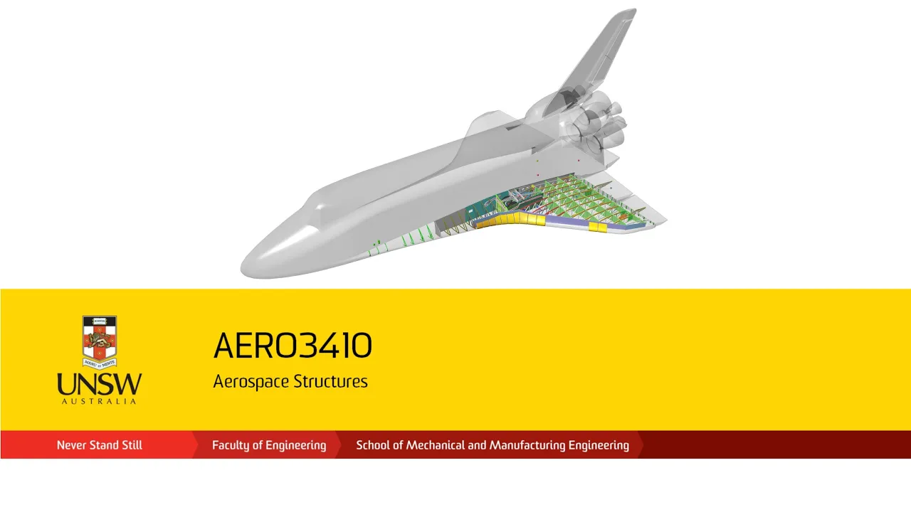
Flutter differs fundamentally from resonance—it is self-excited aerodynamic instability without external periodic driving. The Tacoma Narrows Bridge collapse was actually flutter, not resonance. Control surface flutter occurs when surfaces lag behind wing bending motion, creating positive feedback. Balance tabs shift CG toward hinge, eliminating lagging effects. Wing flutter is the coupling between bending and torsion modes of the entire wing structure. Since the center of mass typically lies behind the elastic axis, disturbed wings create pitch-up motions generating lift. Torsional stiffness restores the wing while bending stiffness decelerates downward motion. This creates coupled oscillations where angle of attack lags behind velocity. The two-degree-of-freedom model with bending displacement h and torsion angle α captures this behavior, requiring matrix formulation for solution. Cross-coupling arises from separation between elastic axis and center of gravity. Matrix formulation converts coupled equations to [M][x]'' + [C][x]' + [K][x] = 0. Complex frequency analysis with s = γ + iω determines stability: positive γ indicates exponential growth (flutter); negative γ indicates decay. Flutter speed increases when bending and torsion frequencies are separated. Key design guidelines include high torsional and flexural stiffness, elastic axis behind aerodynamic axis, high wing taper, large control surface chord, and balance tabs.
Click to watch →

Aeroelasticity - Introduction to Flutter
31.4K
Aeroelastic flutter is a self-excited oscillation phenomenon that occurs when aerodynamic forces interact with structural flexibility in aircraft wings, causing coupled bending-torsion vibrations that can grow indefinitely at certain velocities. The analysis uses a two-degree-of-freedom model with Lagrange's equations to derive the equations of motion, incorporating kinetic energy (translational and rotational components), potential energy (bending and torsional stiffness), and aerodynamic generalized forces. Solving the characteristic equation yields complex frequency solutions where the real part indicates damping (negative for stable, positive for unstable) and the imaginary part indicates oscillation frequency. The critical flutter velocity (VA) is determined from the damping plot, representing the design limit below which the aircraft remains stable.
Click to watch →
The engineering required to fly fast (GVT)
203K
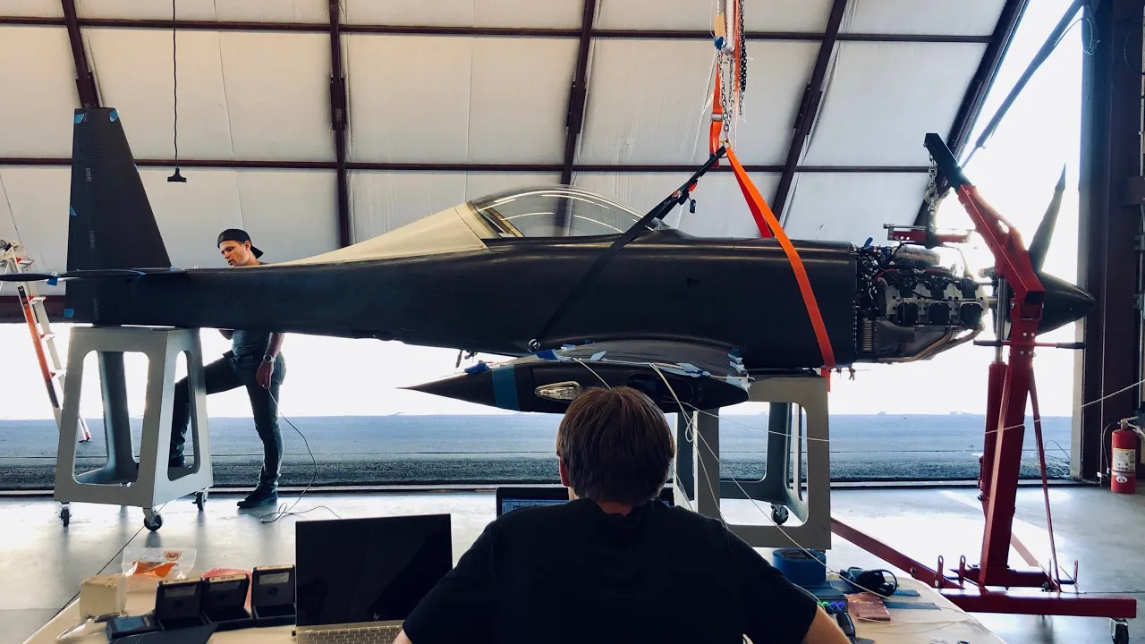
Aeroelasticity studies how air loads deform aircraft structures and how these deformations affect performance. The fundamental model uses mass-spring-dashpot systems where mass represents inertia, springs represent stiffness, and dashpots model damping. Natural frequency determines oscillation rates, while damping (expressed as zeta) determines stability—positive values mean decay, negative values mean instability. Adding multiple degrees of freedom creates mode shapes, which are specific ways structures deform. Two critical phenomena emerge: divergence (unstable pitch-up from improper spring placement) and flutter (coupled heave-torsion oscillations). These effects can cause catastrophic failure if not properly analyzed and designed against.
Click to watch →
Deep Dive
Modern bridge aerodynamics, including the use of open truss designs, aerodynamic deck fairings, and wind deflectors.

Seminario Virtual Efecto del Viento en Puentes de Gran Luz
258
Modern bridge design uses aerodynamic section shapes to avoid dynamic wind problems. The Severn Bridge (1966) used an open-section deck with openings that allowed wind to pass through, reducing aerodynamic forces. The Cernunnos Bridge (1961) by Leonhard proposed a box-section with a smooth, aerodynamic shape. The Bosphorus Bridge (1,410 meters span) and the Messina Strait Bridge (1,624 meters span, 1998) used box-sections with good torsional stiffness. However, for spans approaching 2,000 meters, box-sections alone cannot achieve the required critical velocities (60-80 m/s). The Akashi Kaikyo Bridge (1,991 meters span) used a truss-section with 14 meters depth, with vertical stabilizers that break flow lines and improve aerodynamic stability.
Click to watch →

The Longest Bridge in the World (S9, E7) | Modern Marvels | Full Episode | History
1.1M
The two center lanes of the Mackinac Bridge are built of open steel grates instead of solid surfaces. This design feature serves an important aerodynamic purpose: winds off the Great Lakes have been clocked at over 100 miles per hour, and the open roadway allows wind to flow harmlessly through rather than catching it like a sail. Combined with low side railings and slender suspension cables, this gives the structure an airy feel that reduces wind resistance and prevents dangerous oscillations.
Click to watch →

How the 1940 Collapse Taught Engineers What Modern Computer Models Miss
258
Wind testing began during construction and continued through the final months of 1882. Workers reported that the bridge barely moved during 30 mph gusts that would have set European suspension spans into dangerous oscillations. The open truss system performed exactly as John Robling's empirical analysis had predicted, splitting wind flow into multiple streams that created downward pressure rather than the lateral forces that destroyed solid deck designs. This aerodynamic performance validated the empirical approach that had guided American bridge building for 50 years, demonstrating that physical testing could reveal structural behavior that mathematical models consistently underestimated.
Click to watch →
Zıplayan Köprü: Tacoma Narrows Felaketi
525
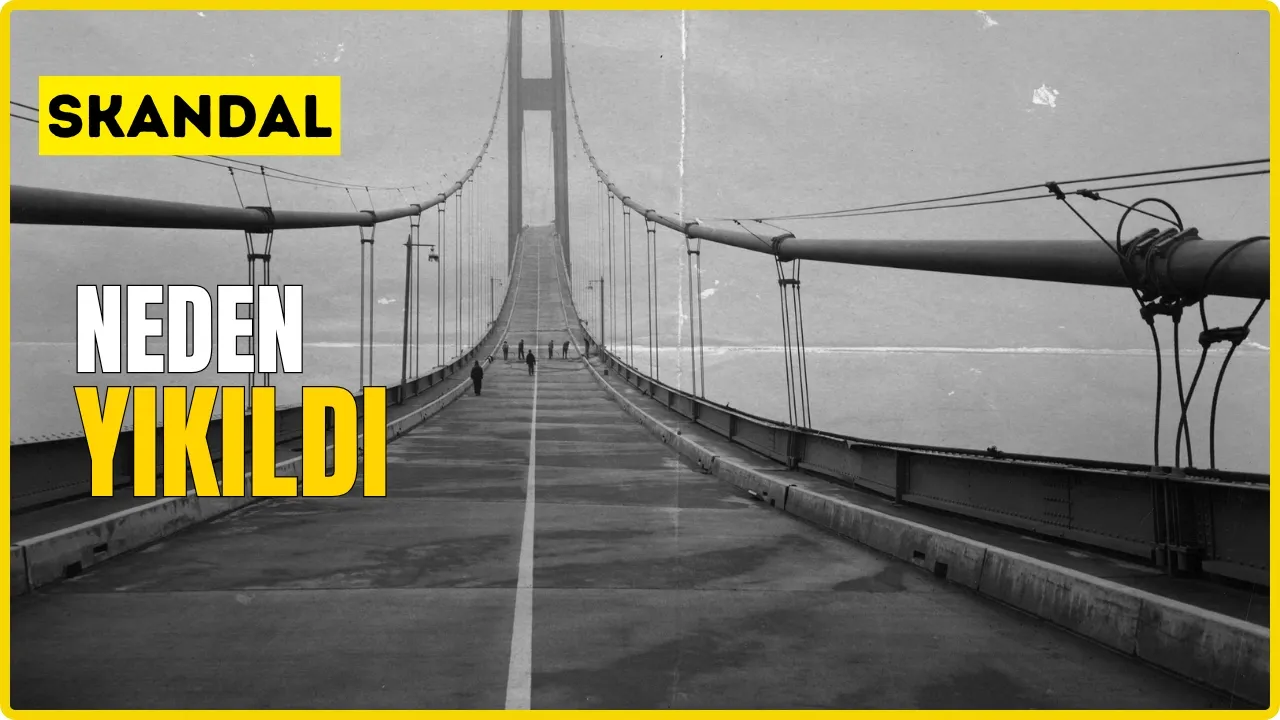
After the Tacoma Narrows collapse, bridge engineering changed radically. Truss structures, aerodynamic decks, and wind tunnel testing became standard components of modern bridges. Bridges no longer needed to be simply strong; they also had to account for how they behave in the wind. Modern suspension bridges incorporate aerodynamic surfaces, openings that allow wind to pass through, and vibration damping systems that silently protect the bridge from destructive oscillations.
Click to watch →

Los ingenieros estadounidenses dijeron que esto era irreal, pero China les demostró que estaban...
1.4K
Engineers chose a truss (lattice) design for the bridge deck rather than a solid flat platform. The Huajiang Canyon acts as a natural funnel for wind, with air currents reaching extreme speeds. A solid platform would create extreme pressure against the wind, potentially destroying the structure. The truss design allows wind to pass through, reducing force on the structure.
Click to watch →
Deep Dive
The integration of physical wind tunnel testing and Computational Fluid Dynamics (CFD) in modern structural design.

How F1 Wind Tunnels Work
202.1K
Computational Fluid Dynamics (CFD) and physical wind tunnel testing work together as complementary tools in modern F1 aerodynamic development. Wind tunnels provide empirical validation of CFD predictions, while CFD allows rapid iteration before physical parts are manufactured. As teams aim to reduce wind tunnel time due to cost and efficiency pressures, clever programs and smart partnerships between CFD and physical testing become essential for confidence in data accuracy within limited testing windows.
Click to watch →

How Carbon Wheels Are REALLY Designed?
35.8K
Modern carbon wheel development integrates wind tunnel testing with Computational Fluid Dynamics (CFD) modeling. Wind tunnels serve as the final validation step, confirming data from CFD simulations and real-world testing. CFD enables manufacturers to run thousands of rim profile variations virtually within a month, eliminating the need for physical prototypes. This computational approach allows precise fine-tuning of aerodynamic characteristics before manufacturing, representing a fundamental shift from early 20th-century methods that relied solely on physical prototyping and wind tunnel testing.
Click to watch →

Dallara: The Expert Racecar Builders Who Have Their Hands In Almost Every Motorsport
47.6K
Modern aerodynamic development combines Computational Fluid Dynamics (CFD) simulations with physical wind tunnel testing. CFD uses computer algorithms to simulate airflow around virtual models, showing streamlines and pressure distributions. Wind tunnel testing provides experimental validation by measuring actual forces on physical models. These two approaches must be correlated closely and continuously throughout the development process. Engineers first perform CFD analysis, then validate results against wind tunnel data, iterating between both methods based on budget and time constraints to ensure reliable aerodynamic predictions.
Click to watch →

LA GRAN VENTAJA DE COLAPINTO, ALONSO Y CHECO PARA MIRAR HACIA ARRIBA EN 2026, UNA NUEVA F1 REVUELTA
26.5K
CFD acts as a multiplier that makes wind tunnel testing infinitely more effective. The video explains that without adequate CFD studies, teams are essentially 'killing flies with cannons' - they don't know which pieces to test. Alpine's 2,300 CFD pieces allow them to identify which specific components need physical testing, while Williams' 100 pieces limit their options. The FIA regulates CFD usage to maintain fair competition, limiting both hours and computational power. Alpine, being last in the standings, has the most CFD hours available, creating a direct competitive advantage through the FIA's allocation system.
Click to watch →

Behind the History of the Legendary Wind Tunnel 1!
50.6K
Aerodynamic components are first designed and tested using Computational Fluid Dynamics (CFD) simulation. Components showing promise from CFD analysis are then manufactured as scale models and tested in the wind tunnel. This two-stage process involves both excitement when results confirm theories and frustration when wind tunnel results contradict expectations, requiring deeper investigation into why discrepancies occur.
Click to watch →
Deep Dive
Case studies of post-1940 suspension bridges (such as the Severn Bridge or the Mackinac Bridge) that implemented lessons from the collapse.

Prof. Henry Petroski: "The Paradox of Design: Success through Failure"
4.5K
After the Tacoma Narrows collapse, engineers learned that unstiffened decks vulnerable to wind excitation were dangerous. The Mackinac Bridge (1957) returned to principles of deep decks and open gridwork allowing wind to pass through. British engineers developed wing-section designs for the Severn Bridge, using angled suspenders to reduce wind effects. The Kashiwagi Bridge (1998), the world's longest suspension bridge at over 6,000 feet, returned to Roebling's advocated deep trusses. However, cable-stayed bridges, which became popular for distinctive signature designs, began exhibiting unexpected cable vibrations in the 1990s. This pattern mirrors what happened with suspension bridges in the 1930s-1940s, where engineers similarly failed to anticipate aerodynamic phenomena. The prediction is that the next major traumatic bridge failure will likely involve a cable-stayed bridge, as designers forget the historical caveats about these bridge types' limitations. Original cable-stayed bridges were intended for spans under 1,200 feet, but modern designs now exceed 3,000 feet, pushing beyond their original intended parameters.
Click to watch →
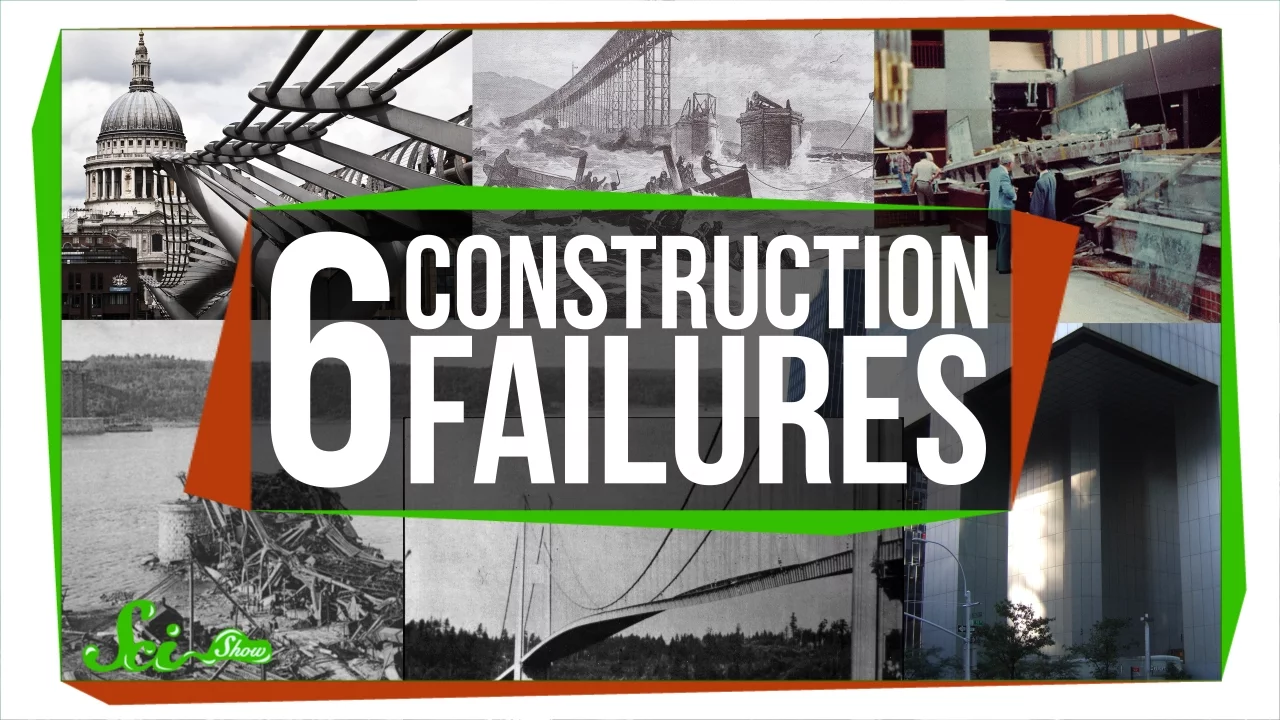
6 Construction Failures, and What We Learned From Them
2.3M
The Tacoma Narrows Bridge in Washington State opened in 1940 but collapsed four months later during a strong windstorm. Unlike previous bridge failures, only one person (a dog named Tubby) died. The collapse occurred due to a phenomenon called aeroelastic flutter: when a cable snapped, one side of the bridge dropped slightly, causing other cables to pull up like stretched rubber bands. Each twist received a small boost from the wind, and these small boosts accumulated over time until the bridge twisted apart. Engineers learned this lesson quickly and reinforced the Bronx Whitestone Bridge, which still stands today.
Click to watch →

Succeed by Failing: Crash Course Kids #42.1
288.6K
The original Tacoma Narrows Bridge, nicknamed 'Galloping Gertie,' opened in July 1940 but collapsed in November 1940. The failure point was wind hitting the bridge at a specific speed and angle, causing it to twist back and forth until collapse. No one was hurt. Engineers learned from this failure to design stronger suspension bridges that could withstand similar wind conditions.
Click to watch →

Duke Engineering TALKS: Henry Petroski, PhD
1.8K
The Tacoma Narrows Bridge (1940) represented an extreme case of insufficient stiffness at 2,800 feet with an unfavorable width-to-length ratio. It collapsed in November 1940 due to torsional oscillations, captured on film as a landmark failure. The investigation confirmed wind as the primary enemy of suspension bridges and flexible decks as particularly vulnerable. Remarkably, John Roebling had discussed these phenomena in 1841. The rebuilt bridge incorporated deep trusses and wider roadways. Post-WWII saw suspension bridge revival with the Mackinac Bridge and Akashi-Kaikyo Bridge, incorporating lessons from historical failures.
Click to watch →

China's Mega Bridges Collapse Months After Opening
30.8K
Major infrastructure booms throughout history have paid tuition through failures that ultimately improved engineering standards. The Quebec Bridge collapsed twice during construction, killing 88 people total (75 in 1907, 13 in 1916), establishing cantilever bridge standards still used today. The Tacoma Narrows Bridge collapsed 4 months after opening in 1940 due to aerodynamic flutter—a phenomenon engineers didn't fully understand—which created an entirely new field of bridge aerodynamics and made wind tunnel testing mandatory for all major suspension bridges since. The Morandi Bridge collapse in Genoa, Italy in 2018 killed 43 people when proprietary cable designs trapped moisture causing corrosion that reduced cable strength by up to 20%, proving that innovative structures need redundancy, regular inspection, and maintenance for decades. The FIU pedestrian bridge collapse in Florida in 2018 killed six people when load miscalculations went unaddressed and visible cracks were ignored, demonstrating that schedule and cost pressures cannot override safety. Every bridge failure becomes a teacher, and every investigation report becomes a blueprint for safer future construction.
Click to watch →
Deep Dive
The evolution of structural engineering building codes and safety factors regarding dynamic wind loading.
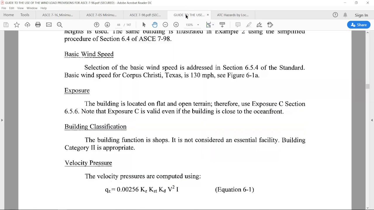
WIND LOAD MANUAL CALCULATION FOR LOW RISE BUILDING
5K
ASCE 7-16 fundamentally redefined wind load as an ultimate load rather than a service load, unlike AC 7-05. This philosophical shift caused wind speeds to increase significantly—from 125 mph to 144 mph for Risk Category 2 buildings, approximately a 15% increase. Consequently, load combination factors changed dramatically: wind was multiplied by 1.0 in AC 7-05 but reduced to 0.6 in ASCE 7-16 strength design combinations. The importance factor changed from 1.0 to 1.0 for risk category 2, and a new elevation factor (Ke = 1.0) was introduced. These changes affect all subsequent design calculations and demonstrate how code evolution impacts structural engineering practice.
Click to watch →
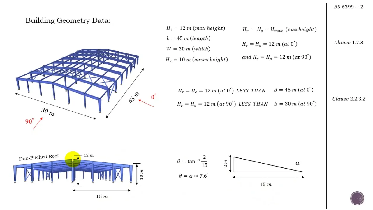
Part 2: BS 6399 Wind Load Example (Wind Dynamic Pressure)
26.6K
Before applying wind load codes, buildings must undergo dynamic classification to determine if static analysis is permissible. Slender or tall buildings may experience excessive movement from wind, requiring dynamic analysis instead. The dynamic argumentation factor CR, determined from building height and type factor KB using Figure 3, indicates applicability—if CR > 0.25 or height > 300m, static code methods cannot be used. For a 12m warehouse with KB=2, CR falls within acceptable limits, confirming code applicability.
Click to watch →

Возможности выполнения динамических расчетов для металлических конструкций в ВК SCAD Office. ч.1
6.5K
SP 20.13330.2016 became mandatory in July 2015. For buildings up to 40m high (multi-story) and 36m high (single-story industrial) in terrain categories A and B, dynamic calculations can use simplified formula 11.5 when fundamental natural frequency exceeds specified limits. The code significantly increased wind load requirements, with equivalent wind pressure now determined by maximum structure height. This increases bending moments by approximately 30% and column moments by about 70% compared to previous codes.
Click to watch →
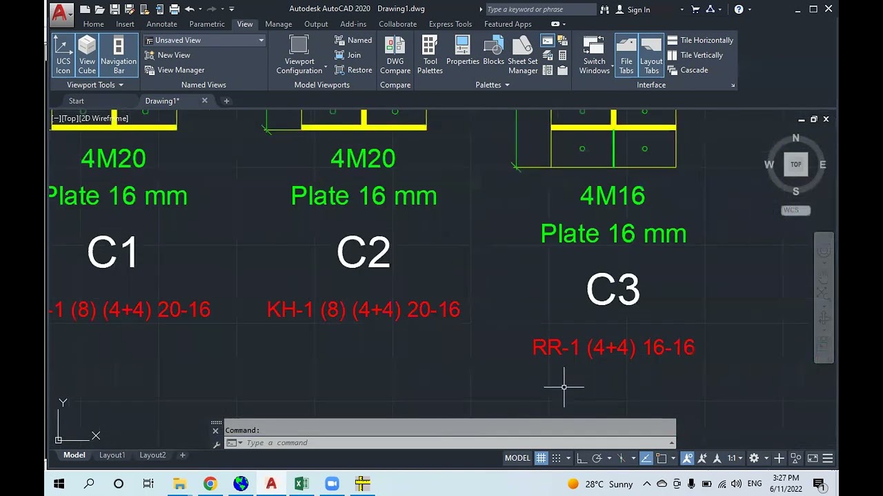
Session2 GMatrix Group
207
Building codes have evolved significantly in their approach to wind load calculations. ASCE 2005 used basic wind speed with a 50-year return period, while ASCE 2010 and 2016 adopted a 700-year return period. The measurement method shifted from fastest mile to three-second gust for greater accuracy. The importance factor (0.87 for poultry, 1.0 for normal, 1.15 for critical structures) was replaced by risk category-based maps in newer codes. This evolution reflects improved understanding of wind behavior and structural safety requirements.
Click to watch →

PART 1 - An Overview of Changes in ASCE 7-22 on Wind Loads
451
ASCE 7-22 introduces significant changes to wind load provisions including updated wind speed maps for 300, 700, 1,700, and 3,000-year return periods, revised topographic effect factors (Kzt), removal of simple diaphragm building definitions and simplified methods, new Chapter 32 on tornado loads, and revised external pressure coefficients for components and cladding on low-rise buildings; these changes have been adopted by the 2024 IBC and are being implemented by major jurisdictions including California (effective January 2026), New York, Washington, and Massachusetts.
Click to watch →
Music Start
Vocal Mix
Final Crescendo
Music Start
0:05- 1
Opening melody begins with rhythmic beats.
- 2
Audience atmosphere sets positive engagement tone.
- 3
Initial sounds cue the main event soon.
Aeroelastic Flutter vs. Classical Resonance Misconception
While many physics textbooks historically attributed the 1940 Tacoma Narrows Bridge collapse to 'classical resonance'—where periodic wind gusts matched the bridge's natural frequency—modern engineering and physics consensus rejects this explanation. Research, notably by Billah and Scanlan (1991), demonstrated that the collapse was actually caused by 'aeroelastic flutter' (specifically, torsional flutter). This is a self-exciting, non-linear aerodynamic phenomenon where the bridge's own twisting motion created aerodynamic forces that further amplified the twisting, leading to runaway oscillations. Teaching the collapse as a simple case of resonance oversimplifies the complex fluid-structure interactions and misrepresents the actual physical forces that structural engineers must design against.
Basic physics of oscillations, including concepts of natural frequency, amplitude, and mechanical resonance.
The fundamental structural components and load-bearing mechanics of suspension bridges, specifically tension and compression.
Introductory aerodynamics, particularly how fluid flow (wind) generates lift, drag, and vortex shedding forces on structures.
The difference between translational motion (vertical/lateral movement) and torsional motion (twisting) in engineering mechanics.
The theory of aeroelasticity and the mathematical modeling of self-excited aerodynamic flutter.
Modern bridge aerodynamics, including the use of open truss designs, aerodynamic deck fairings, and wind deflectors.
The integration of physical wind tunnel testing and Computational Fluid Dynamics (CFD) in modern structural design.
Case studies of post-1940 suspension bridges (such as the Severn Bridge or the Mackinac Bridge) that implemented lessons from the collapse.
The evolution of structural engineering building codes and safety factors regarding dynamic wind loading.
15.3M views33.5Klikes5:56@racingcainOriginal Release: 2006-12-09
[Music] [Music] [Applause] [Music] [Music] Oh [Music] [Music] [Music] Oh [Applause] [Music] Oh [Music] Oh [Music] you you [Music] [Applause] Oh [Music] Oh [Music] [Laughter] [Music] Oh [Music] [Music] [Laughter] [Music] Oh [Music] Oh [Applause] [Music] Oh [Music] Oh Oh [Music] [Laughter] [Applause] [Music] [Music] [Music] Oh [Music] [Applause] [Music] [Laughter] [Music] Oh [Music] Oh [Music]
Up Next

80:29
Language Documentation Training: Audio & Video Recording Tips 2023
@endangeredlanguagesproject
691 views•2023-10-13

12:54
Triumph of Orthodoxy Icon: Byzantine Art & History Explained
@BenCallan
2.1K views•2024-08-06

9:49
FastAPI vs Flask vs Django: Choosing the Right Python Web Framework
@TechWithTim
302.5K views•2024-05-26

1:42
Game of Thrones Opening Credits: A Cinematic Analysis
@gameofthrones
46.3M views•2011-04-18
Related Study Plans & Knowledge Roadmaps
Structured learning paths in General & Interdisciplinary Studies
general-studies
Elevator Engineering: History, Physics & Cities
01From Hoists to Safety Brakes: The Dawn of Vertical Lift
02Hydraulic vs. Traction: The Engineering Physics of Elevators
03Modern Speed, Safety, and Algorithms
+ 2 more learning modules
12h5 modules
Explore Roadmap
general-studies
Rubber: Material Science, History & Geopolitics
01Origins of Natural Rubber & Mesoamerican History
02The Chemistry of Natural Rubber & Vulcanization
03The Geopolitics of the Rubber Boom & Colonization
+ 2 more learning modules
12h5 modules
Explore Roadmap
general-studies
Containerization: Evolution, Logistics & Trade
01Ancient Trade & Bulk Cargo: Amphorae to Barrels
02The Industrial Revolution & Cardboard Packaging
03The Containerization Revolution: Malcom McLean
+ 2 more learning modules
12h5 modules
Explore Roadmap
general-studies
Textile Tech: Evolution, Labor & Global Impact
01Pre-Industrial Textiles: Handloom & Cottage Industry
02Mechanization: The Spinning Jenny to the Power Loom
03The Factory System & Global Labor Transformation
+ 2 more learning modules
10h5 modules
Explore Roadmap