


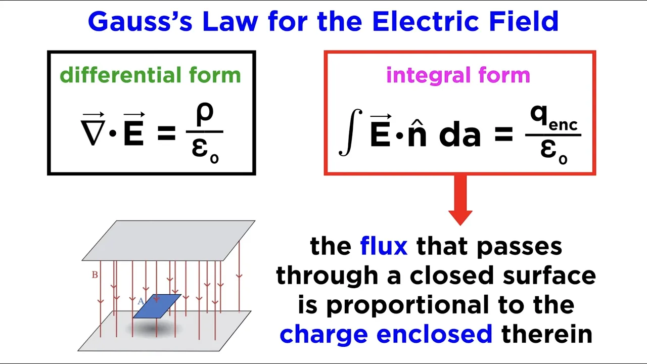
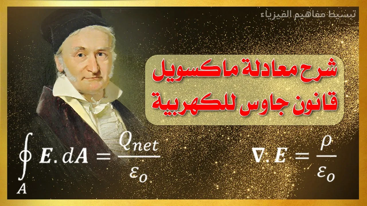






















Electromagnetic waves are generated by oscillating electric currents in antennas, where alternating electric and magnetic fields propagate perpendicular to each other at the speed of light; the strength of received signals depends on resonance between transmitter and receiver circuits, antenna orientation matching the polarization of the transmitted wave, and the standing wave pattern along the antenna where maximum field amplitude occurs at the center for half-wavelength configurations; galvanometer-based instruments measure current and voltage by adding shunt resistors in parallel for ammeters or series resistors for voltmeters to extend their measurement ranges while minimizing circuit loading.
Electromagnetic Waves & Maxwell's Equations: Physics Lecture
Added:Vector Calculus, specifically the concepts of divergence, curl, gradient, and the integration theorems of Stokes and Gauss.
Fundamental Classical Electromagnetism, including Coulomb's law, Gauss's law, Faraday's law of induction, and Ampere's original law.
Basic Wave Mechanics, covering parameters like wavelength, frequency, phase velocity, and the mathematical form of the 1D wave equation.
Introductory AC Circuit Theory, including the concepts of resonance, inductance, capacitance, and oscillating circuits.
Einstein's Special Theory of Relativity, exploring how the constancy of the speed of light in Maxwell's equations demands a fundamental revision of space and time.
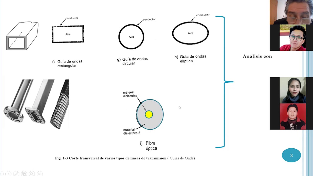
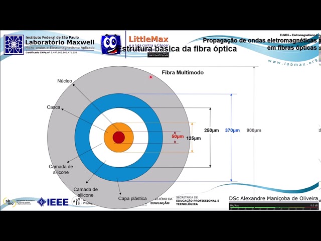
Waveguides, Transmission Lines, and Fiber Optics, studying the propagation and confinement of electromagnetic waves in physical media.
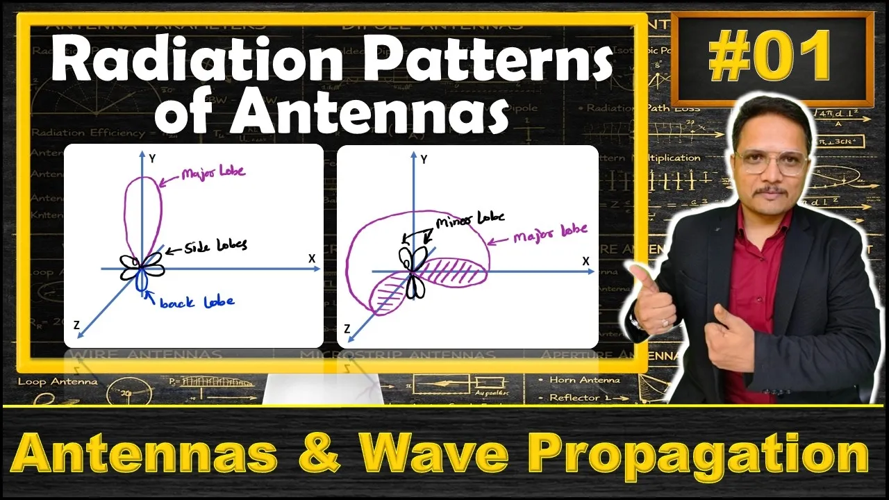
Advanced Antenna Theory and Radio Frequency (RF) Engineering, focusing on radiation patterns, dipole antennas, and wireless communication systems.
Quantum Electrodynamics (QED), examining the quantization of the electromagnetic field and the interaction of light with matter at the particle level.
556.9K views3.3Klikes36:42Original Release: 2009-07-30
this is a production of Cornell University hello today our subject is the propagation of electromagnetic radiation it gives us an opportunity to use some of the most interesting 19th century lecture demonstration apparatuses in the physics departments collection I will be doing things that make lots of sparks and you will in fact one way that you'll know that electromagnetic radiation is being propagated is that sometimes there will be interference lines on the television pick up of the monitor my first experiment is going to be one very similar to that which was done by Hertz to propagate the first radio waves or what we're called Hertzian waves I have here my transmitter which is going to consist of a coil of wire which is an inductor and a capacitor called a Leyden jar and a source of voltage and a spark gap spark breaks down as soon as the electric field becomes large enough to ionize the gas in between the gap so that there is a sudden current flow and following that there's a transient frequency oscillation in my circuit let me talk about the capacitor for a minute because they're very interesting things that were devised in the 19th century these are called Leyden jars early thoughts about the storage of electrical charge conceptually the idea that occurred to people was that there should be stored in a way very like the way they would choose to store tomatoes or peaches in a jar the container has a metal foil and the interior and then another metal foil on the outside so there is an electric field between the metal foil outside and the metal foil on the inside and the dielectric medium in between is just the glass of the jar we make contact with the inner conductor with this spring-loaded device that has an electrode on it make contact with the outer conductor by just letting this rest on a metal plate okay in this circuit then I have one Leyden jar from a capacitor in my inductor the characteristic resonant frequency then is determined by one over the square root of the inductance times capacitance that's the angular frequency two pi times F when I turn on my electric potential the spark gap breaks down and I have an alternating current in my coil and now I can pick this up in a second coil which I have here there no other wires attached to this coil when the currents flowing this way in the loop there's going to be a magnetic field pointing that way when the current was this way in the loop there's going to be a magnetic field that way and this alternates at a rather high frequency over in my second loop this alternating magnetic field and there's also an electric field associated with it around it the alternating magnetic field produces an EMF in the loop and that's picked up and it can cause a discharge in a neon bulb that we see down here if I rotate the plane of the loop and my second coil which is really an antenna this you can think as being something like a an unusual radio station if I rotate this to be 90 degrees away there's no flux changes in the loop and the loop doesn't work but the total flux change in the loop is not the only thing it determines the strength of the signal that can be propagated in my second coil picked up on my second coil it has to have a frequency a resonant frequency that's close to the resonant frequency of my transmitter for instance if I change the dimensions of my picked up coil by just making the loop bigger if the only thing that were involved is an increase in the the change in the magnetic flux in the second loop you might expect it to have an even brighter glow in my neon ball but that's not the case when I increase the area of this loop I increase the inductance and it's no longer near the resonant frequency of my source you'll see that when I lower this again I can get the neon bulb Wow well this is basically the type of apparatus that Hertz discovered that could use for the propagation of waves in the frequency range around one megahertz a million cycles per second let me turn this off and we will go on to an apparatus that looks like one used in by dr. Frankenstein for his experiments and that's that this experiment set of experiments that I'm going to do with another tuned circuit but this time I'm attached to a very strong voltage source I have over here a transformer with enough turns in it so that the voltage that's on the output of this transformer is sixty thousand volts when I hook it up to the hundred and ten volt mains and now I'm going to connect that to another LC circuit that also has a spark gap and you'll see a very bright spark when this is running and the frequency of this one is around Omega Hertz alright for my first experiment that I will be doing in in this circuit I have here three of these capacitors I have an inductor in the circuit and a spark gap you will see the bright spark when it's activated and I'll have a coil that I'll attach in the circuit so I'll have a very strong alternating magnetic field in this loop when I activate the circuit and will do several experiments in it let's go ahead turn it on then please this first experiment is one similar to one we've seen before I have a roof for the light bulb in it and I placed this in front of my circuit and you'll notice the light bulb glows this is very similar to an experiment that we demonstrated earlier for Faraday's law the alternating magnetic field and here is picked up by the alternating is is picked up in my second coil and I get an alternating electric field in the loop which causes the light bulb to glow the second demonstration with this is a little more unusual here I have a glass bulb that has a low pressure of air in the bulb watch what happens when I place this within the you'll notice a ring now what happened there the gas in the tube was ionized and you saw a circular ring of of ions the reason that we had the breakdown in that pattern is because we had alternating magnetic field this way that according to Faraday's law and induces an EMF and a circle around the outside and where it's going to be the strongest there and it was sufficiently large to cause the electric field in that region was sufficiently large to cause a breakdown in the gas in that region in the gas glass bulb I can cause a breakdown in gas in the air with another apparatus and I'm going to next demonstrate and that's called a Tesla coil I'm going to make construct another form of transformer and this time to an even larger voltage I'm going to attach a coil similar to the one that we used before to the same terminals but place within it a second coil that has a much larger number of turns so that the potential that's generated in the second coil is close to a megahertz and then we will do several experiments with it I'm going to change the tuning of my circuit for coupling into this coil and now at the top of the coil there's a small wire and that's a region in space in which I'll have the largest electric field and when the experiment begins you will see a lot of blue sparks coming off and that's the actual breakdown of the gas in the air called corona I will do several experiments with the Corona discharge from the Tesla coil the first one will be that I will hold this glass bulb which is just a bulb with a wire attached to it up in the air and I will in fact then cause the bulb to be lit and in this experiment my body will be the return path that completes the circuit for the electricity in the coil I will feel a tingle and you suck might see me flinch but it's not particularly dangerous because at this frequency but as a megahertz the electricity does not penetrate into my body very deeply it just flows on the surface and it will flow back down to ground potential on my body then I will also hold up several other glass bulbs and you will see a fluorescent light glow and you'll also see the breakdown of hydrogen gas in an another tube for this segment I'm going to take off the microphones because of the interference from the spark Louise our next demonstrations come from a vintage in time 50 years more modern than the million-volt tesla coil we demonstrated and we will be studying now the properties of dipole antenna let's consider an electric dipole that is we have a positive charge and a negative charge and let's hook them up in a wire there's an electric field line that will go set of lines and go from the positive charge to the negative charge now if I arrange to change the potential on each end of my wire so that this end becomes minus and that in becomes positive the electric eel lines that come out will reverse in the direction so they go in the opposite direction and that's the basic way that we can transmit with a dipole antenna electromagnetic radiation during part of the cycle we have the top-end positive in the bottom and negative electric field lines coming out like that and when we will reverse it we look out here at a certain distance will see electric field lines that are up for part of the cycle down for part of the cycle let's insider' then what happens the magnetic field at the same time because when we reverse the direction of the polarization the electric potential in my rod I have to change the current that's flowing in the rod and I will have a maximum current flowing when I in the middle of my cycle change and there will be a magnetic field going radially around the rod consider this rod if I have a alternating electric field in the rod there's going to be current going down the rod and there's going to be a magnetic field going radially around the rod the currents going up the magnetic field is making circular loop like this so each time I have current flow in my rod I have a magnetic field associated with that and it's going to be in circular loops around the rod and as I go out here further and further in space I'm going to have a magnetic field perpendicular to my electric field so during part of the time I'll have a magnetic field that's coming out and the other part of the time a magnetic field that's going in let's demonstrate some of this with an apparatus here here I have a tube transmitter for my source and an antenna that's coupled to the source oscillator so I have an alternating electric potential placed across this antenna and now I will use for receiver just this rod and a light bulb and you'll notice that the light bulb glows in quite a distance away from the source their clothes most brightly when I go closer and closer to it and get closest to the source of course because the strength of the electric field that radiated decreases as I move further away from the source I also get at a given distance away from the source a maximum amount of signal that I can receive if I have this rod parallel to that rod and that's because the electric field lines that are coming out of that source are parallel to the rod if I make this perpendicular to the direction of the electric field lines the light bulb doesn't glow even if I go quite close to the source on the other hand if I turn it back so that it's parallel to it I can make the bulb glow bright enough to actually burn out the ball there's another aspect to this this the length of the antenna is important if I make the antenna very much longer I have to go quite a bit closer to the source to get the same amount of brightness this once again is is a resonance phenomena like the one that we had in Hertz's experiment let's look in fact at the strength of the electric field along such an antenna rod by having an antenna that has lots of lightbulbs on it and now you'll notice that as I go close to the transmitter or so that they're glowing right enough the ones near the center are blowing quite brightly and the ones on the ends are barely glowing at all that's because the strength of the electric field or the amount of current in in the circuit is largest in the center and falls off on each end this in fact is then a half wavelength of the light and going from here to there or my electromagnetic radiation I have my maximum amplitude of electric field in the middle and I have a node on each end you can see qualitatively why that is the case because in my antenna source and now I could demonstrate in my antenna the fact that it's hooked up to some alternating source by having this hooked up to a amplifier box as a alternating signal okay in my alternating source during part of the cycle this is positive and that's negative and then I reverse that the characteristic distance between them the maximum in the positive direction and the maximum in the negative direction is roughly the dimensions of my antenna the speed of light is 3 times 10 to the 8 meters per second and now we say that this distance is approximately than 1/2 wavelength it is the dimension between the most positive and the most negative and that sort of means a wavelength here is roughly two meters so you can in fact calculate the frequency associated with this electromagnetic wave that's being propagated there's several other possible modes in an antenna could have we could have an antenna in which we have several nodes in the middle so that there are several places in which I have maxima and minima if I want to drive it at a higher and higher frequency in my neck next demonstration in fact is one in which we do that I have in this case a rod glass it has a wire wrapped around it and it's so it's quite a long length of wire wrapped around the rod and I place this in my antenna source and we will test the strength of the electric field along the rod by moving a neon fill bulb beside the rod and if the electric field is strong enough we can cause the neon to break down watch what happens as I move the neon bulb along the rod let me readjust the position of this in the source there you have the neon breaking down at that point which means I have a strong electric field there and as I move further down the rod goes off I should come to a place again later where it comes on again so then I move down further it goes off comes back on again glows weekly goes off comes back on again so characteristic distance about like this is the distance between nodes for the radiation in this case that would be a half wavelength and this would be a wavelength for the standing wave in my antenna of course that's all coiled up characteristic distance is still roughly the same as this for a half wavelength our next demonstration is in a different frequency range yet this is a shorter wavelength and the ones that I've just done and this is at the microwave frequency range I have here a dish antenna source with a dipole in the center that sees a high frequency oscillation on this little metal rod in the center so the characteristic wavelength is roughly something like this of order 3 centimeters once again you should make a calculation to estimate the frequency of this radiation and because the dipole is pointed this way we know the electric field polarization is in the up and down direction and it's propagating outward from that dish source we have a receiver here which is a very simple device it's a meter with a little diode attached to it and as the electric field alternates across a diode it produces a current that can be detected in the meter so we have a deflection on the meter due to the microwave radiation that's coming to it we can do some simple experiments with the radiation one thing let's see what happens when I place a piece of metal in the path of the microwave radiation and what you should observe is that the amplitude of the an electric field intensity at this point is very much weaker that's because the metal is a very good reflector for light at the microwave frequency as well as it is for visible light I have a piece of bakelite here which of course completely is opaque to visible light that is no visible light gets through it very easily now watch what happens when I put this in the path of the microwave radiation very little this is invisible or practically invisible at the microwave frequency so that if you and I had our eyes tuned to work at microwave frequency we could see through all sorts of walls and and other things if if it behaved in the way that does for this bakelite demonstration my next demonstration is related specifically to the polarization of the radiation that comes from this source we know that we have the dipole antenna in the up-and-down direction so the electric field is in the up-and-down direction now this object is just a disc with a bunch of parallel conductors wires and a grid the question that I want you to think about is which orientation will disturb the microwave microwave propagation most when I place it so that the wires are parallel to the electric field or perpendicular to the electric field let's try this direction when you put the the grid so that it's perpendicular to the electric field lines in the propagation in this direction or you see that very little happens on the other hand when I rotate this 90 degrees you have an experiment similar to this that you will be doing in the course you'll see that the radiation is absorbed well part of one of the experiments you'll be doing is to understand that phenomena but the answer is not that the radiation is polarized with the electric field in that direction the electric field is in fact in the up and down direction I want to conclude with a vector relate steel magnetic and electric field in a traveling wave you remember in my dipole I had an electric field amplitude that was oscillating in the up and down direction and I had then in the plane perpendicular to that a magnetic field that was oscillating that's a general result in set of equations called Maxwell's equations when the electric field is at a maximum I also have a maximum magnetic field which is represented by this blue arrow there's a vector relation in fact between the direction of the electric field in a wave the magnetic field in the wave and the velocity of propagation which is that way it's another one of the right-hand rules the velocity of propagation is in the direction of e cross B so you turn E and do B with the right hand and the thumb points in the direction of propagation so all this radiation one should imagine as being such that I have these oscillating electric and magnetic fields that are moving along at the speed of light we want to talk now about the instruments that are used for measuring voltages and currents there are two classes of these instruments there's a modern solid-state set of instruments that typically have digital readouts that are for voltage and current reading and then there's another group of instruments that are based upon measurements of electromagnetic forces in an instrument called a galvanometer and the discussion today is going to be about instruments based upon the the principle of a galvanometer and the basic idea here this is the the wall elements of such a galvanometer is that we have usually a permanent magnet which is this red horseshoe magnet that I have here and a coil when I pass a current through the coil it produces a magnetic moment that interacts with the permanent magnet and I get a force which can cause a deflection of my meter and I have current going one way and you'll notice that the pointer goes in one direction if I reverse the current by just changing the terminals on the battery the torque is in the opposite direction and I have the meter deflection in the opposite direction because I have a magnetic moment that's proportional to the current passing through this coil that produces a torque when it's in this permanent magnet and the size of the torque is proportional to the current through the loop so the galvanometer is intrinsically an instrument that gives us a deflection that's proportional to the amount of current that goes through it the amount of the deflection depends upon the spring constants and if we look at some of these meters that we have over here for instance this one you will see that there is a tight spring that looks very much like a watch spring that controls the the balance in the torque and the motion of the meter can be used for damping the meter and so forth all right this one basic instrument can be used to measure a variety of it's and also can be used to measure potential differences let's look at how we modify the instrument by addition of extra elements in order to make it a a meter with a specified current range or a voltmeter suppose this instrument had for its basic deflection full-scale that is that the meteor deflected full scale with one milliamp and that the electrical resistance of my coil is one ohm that means without doing anything else to it I'll get a full scale deflection of our meter with one milliamp current passing through it and the thing that I will have would understand to mean when I write the symbol a and some sort of a circuit through which I want to pass current is that I have a device that has a resistance of 1 ohm and it will be full scale deflection with a 1 milliampere current passing through it suppose I wish to modify that in order to have the current be 1 ampere for full-scale well the way this is done is to actually place a very low resistance element in parallel with a meter so that most of the current passes through this shunt is the name of this element instead of through the meter we just bleed a little bit of current in parallel through the meter so I have 1 ampere going into a network that will contain the meter and my parallel resistance element this will be my resistor R in parallel the shut resistance and now I have 1 ohm going through the gal for one milliamp going through the galvanometer and now in order to calculate how much resistance I have to put in parallel I observe that I have 1 ampere going into the system and it wants to split with a certain fraction of the current going through the shunt resistor and one milliamp going through the meter itself well the current I'll be obviously has to split so that 999 milliampere years go through the resistance R and that has to be a much smaller resistance than the resistance of the meter itself and the size of that resistance is just proportional to the ratio of the currents that is one milliamp / 999 milliamps current going from the upper branch must be equal to the resistance R divided by 1 ohm okay so that evidently R should be equal to if I say this is 10 to the minus 3 amperes to put that in resistance it's going to be equal to one point zero one times 10 to the minus 3 ohms so I can make this meter into a meter that reads one ampere full-scale by adding a very small resistance in parallel approximately 10 to the minus 3 ohms now there is a correction that one sometimes has to worry about with meters in the case of my Ana meter here it does it has a finite resistance and it can change the amount of current that flows in the circuit when I install it for instance back as a milli ammeter let's see how it would change the current flowing in a simple circuit suppose I have a 1 volt battery and I install my milli ammeter here in series with that and 1000 ohms if I have no resistance in my meter if it's perfect or if I just put a short circuit around it for the time being then the current flowing in this circuit I equal V over R would be equal to 1 over 1000 would be equal to 1.0 times 10 to the minus 3 or 1 milliampere but with a real meter where I have a real resistance of 1 ohm when I'm making my measurement the total resistance in the circuit now is going to be 1000 ohms plus 1 ohm so that I will have 100 1 here and then the current that will flow through the circuit will be 0.999 and I will have a small correction because this is not a perfect meter an ideal ammeter is one with zero electrical resistance of course we can't approach we can only approach the ideal case suppose I wish to make this instrument into a voltmeter now voltmeter is an instrument that is used to measure the potential difference between two elements in a circuit and we can arrange this so that some of the current in the circuit is bled off to pay us through the galvanometer to cause a deflection that's proportional to the voltage for instance using the same meter again suppose I wanted to measure the potential drop across a resistor here's a resistor R and there's a current I flowing through it and I want to know what the potential drop between this point and that point might be and the way I achieve this is by placing a resistor in series with my galvanometer so that I have the desired calibration features for instance suppose I wish this galvanometers to have a deflection full scale deflection when there is 10 volt potential difference between here and there that is when the potential is V is equal to 10 volts once again the current I in the circuit there would be 10 million mean 1 milliampere so that the resistance that we have to add n is going to be determined by Ohm's law again V equal I times R so for this example I said that the potential was 10 volts the current for that particular meter is 1 times 10 to the minus three amperes and the total resistance will be my extra resistance that I add in series R plus the 1 ohm for my meter we can solve this so R plus 1 is equal to 10 to the fourth ohms and now are the extra series resistance that I need to add to my galvanometers make it into a voltmeter will be equal to 9999 ohms so that if I do that add this resistance in series with my meter it can then be used as a voltmeter pretend that that's in the box and this is typical of the series resistors that were designed to be added to these delicate galvanometers this worked perfectly well until I have to measure the potential drop across large resistors for instance if I had a resistor here of a million ohms and I tried to use this instrument as we've designed it here for a measurement the current would primarily go through my meter itself because it would have only a resistance of 10 to the 4th ohms so that my once again we'll have a a serious correction that I have to apply when I use this instrument and measuring potential drop across large resistors the ideal voltmeter then should have as large a apparent resistance as possible that's another statement is so that it that it the correction comes about because that we want to have the minimum amount of current drained from the circuit in making the measurement the ideal voltmeter should have an infinite apparent resistance the ideal ammeter should have zero resistance
Up Next

17:52
Relativistic Origins of Magnetic Fields Explained
@Mahesh_Shenoy
1.1M views•2022-11-12

12:53
21cm Hyperfine Transition in Neutral Hydrogen: Radio Astronomy Basics
@AaronRobertParsons
12.4K views•2011-10-13

76:31
Nonlinear Dynamics and Chaos: Course Introduction & Overview
@cornellmae1636
422.8K views•2014-05-27

27:14
Entropy and the Second Law of Thermodynamics Explained
@veritasium
27.5M views•2023-07-01
Related Study Plans & Knowledge Roadmaps
Structured learning paths in Physics
physics
Nuclear Physics (Decay, Fission & Reactors)
01Atomic Structure and the Binding Force
02Radioactive Decay and Half-Life
03Nuclear Fission Mechanics and Chain Reactions
+ 2 more learning modules
12h5 modules
Explore Roadmap
physics
Soft Matter (Polymers, Colloids & Rheology)
01Foundations of Soft Matter & Thermal Forces
02Polymer Physics and Macromolecules
03Colloids, Surfactants, and Self-Assembly
+ 2 more learning modules
38h5 modules
Explore Roadmap
physics
Analytical Mechanics: Lagrangian & Hamiltonian
01Mathematical Foundations: Calculus of Variations
02From Newtonian Mechanics to Constraint Dynamics
03The Principle of Least Action & Lagrangian Mechanics
+ 3 more learning modules
28h6 modules
Explore Roadmap
physics
General Relativity (Spacetime & Cosmology)
01Foundations of Relativity: Special Relativity
02The Geometry of Spacetime: Equivalence Principle & Curvature
03Einstein's Field Equations: The Mathematics of Gravity
+ 2 more learning modules
55h5 modules
Explore Roadmap