

















This tutorial explains how to use Arduino's 10-bit analog-to-digital converter (ADC) to read varying voltages from sensors like photoresistors and thermistors, covering how to set reference voltages, map sensor values to different output ranges using the map() function, and control analog outputs like LED brightness proportionally based on sensor readings.
Analog Inputs with Arduino: Voltage Dividers, Sensors, and Mapping
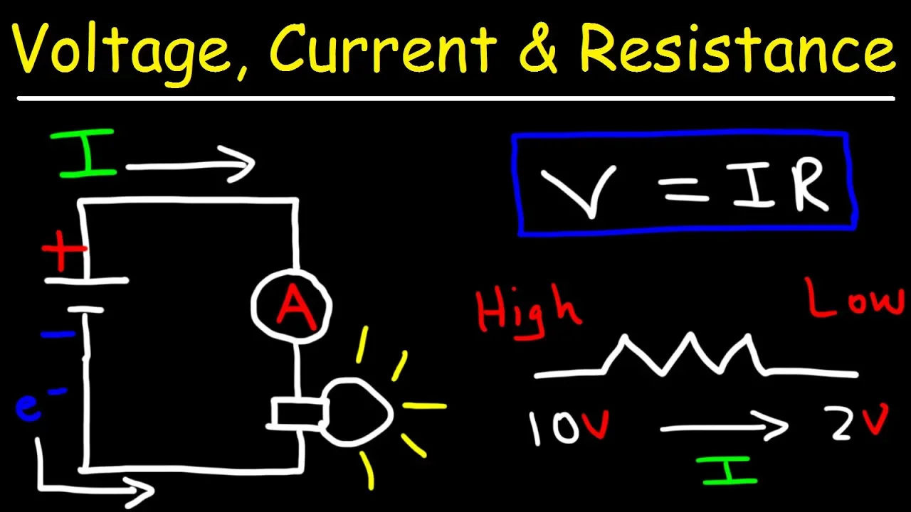
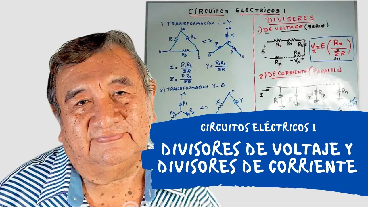
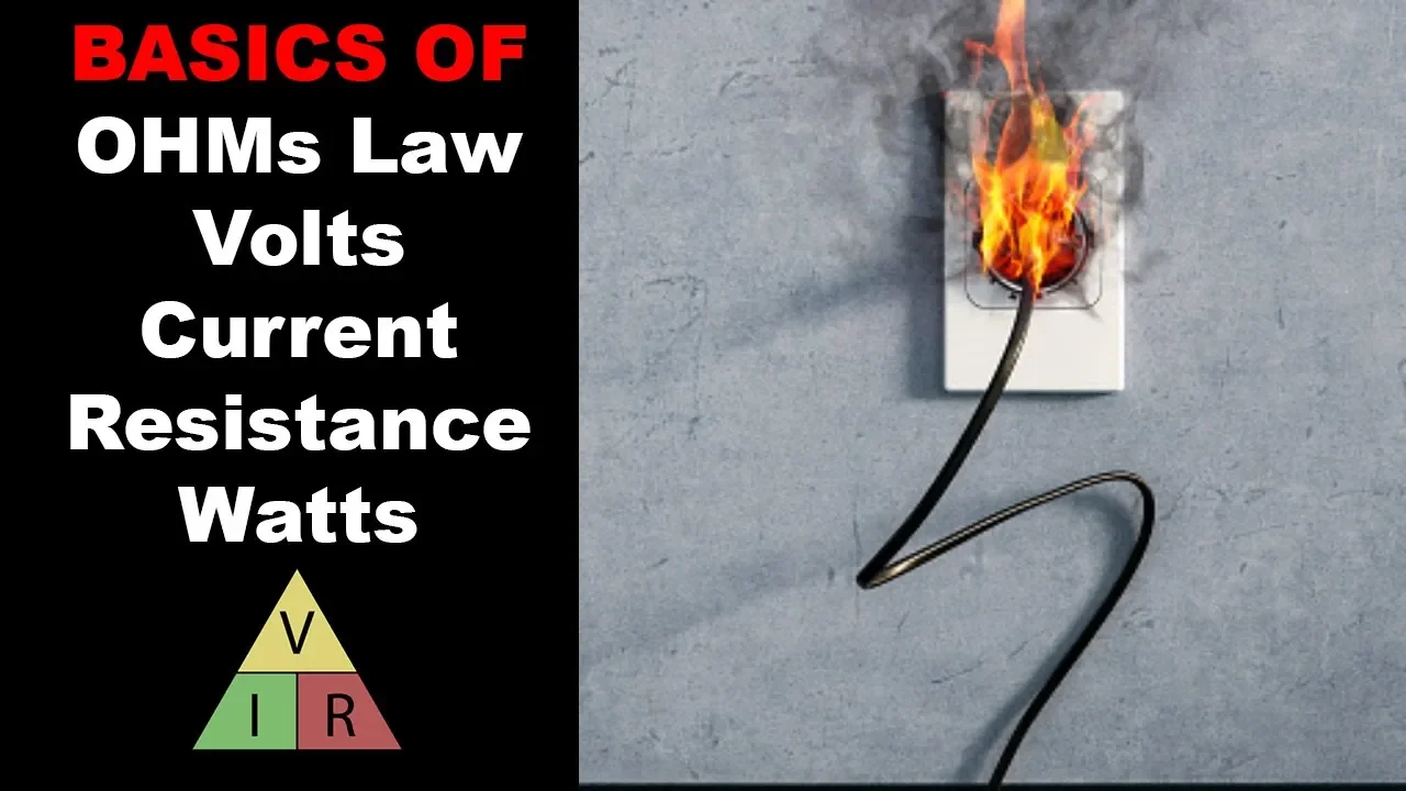
Added:Fundamental electrical concepts such as Ohm's Law, Voltage, Current, and Resistance to understand how voltage dividers manipulate signals.
The conceptual difference between digital signals (discrete binary states) and analog signals (continuous range of values).
Basic Arduino programming proficiency, including declaring variables, configuring pin modes, and utilizing the serial monitor for debugging.
Familiarity with breadboarding and connecting basic electronic components like resistors and LEDs.
Implementing software-based noise reduction and signal filtering techniques, such as moving averages, to stabilize fluctuating analog readings.
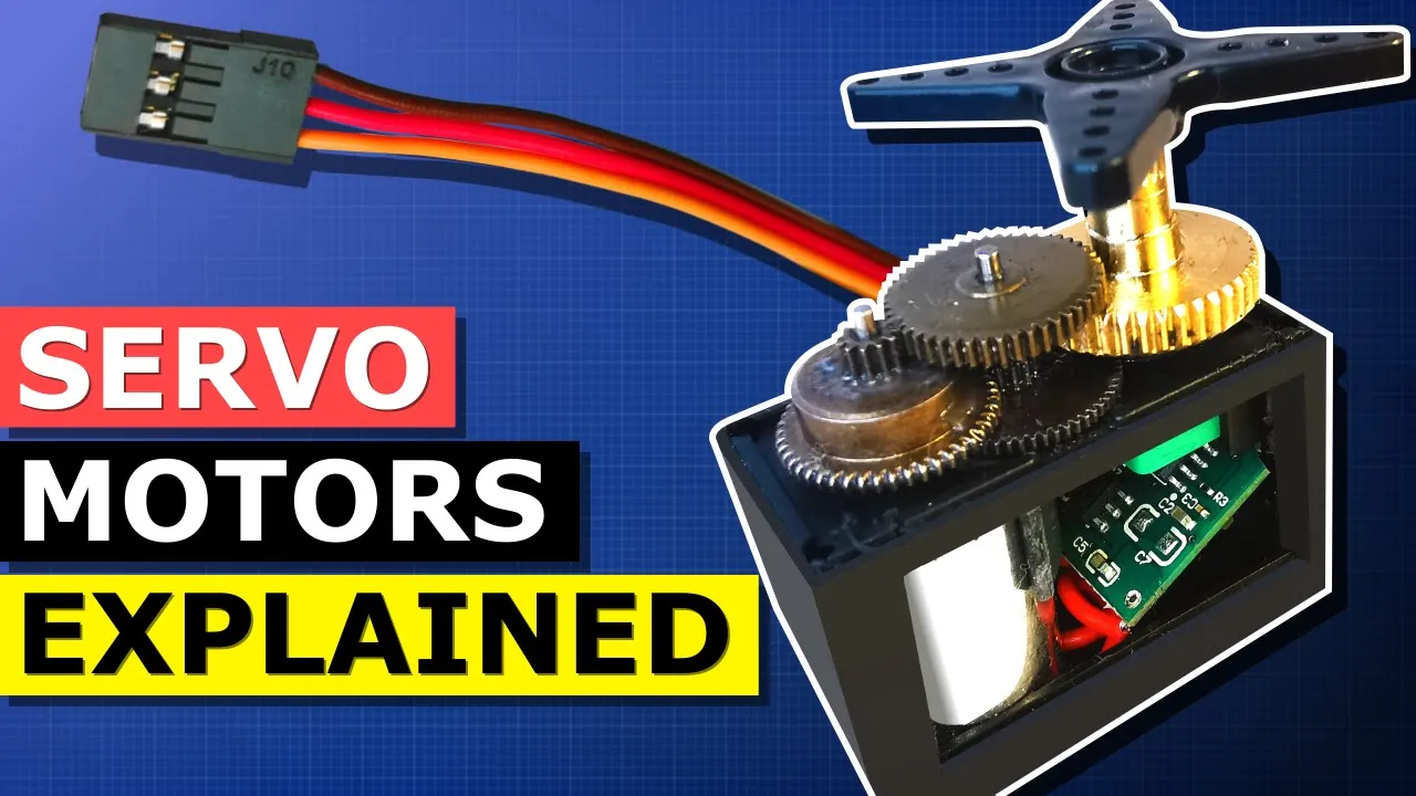
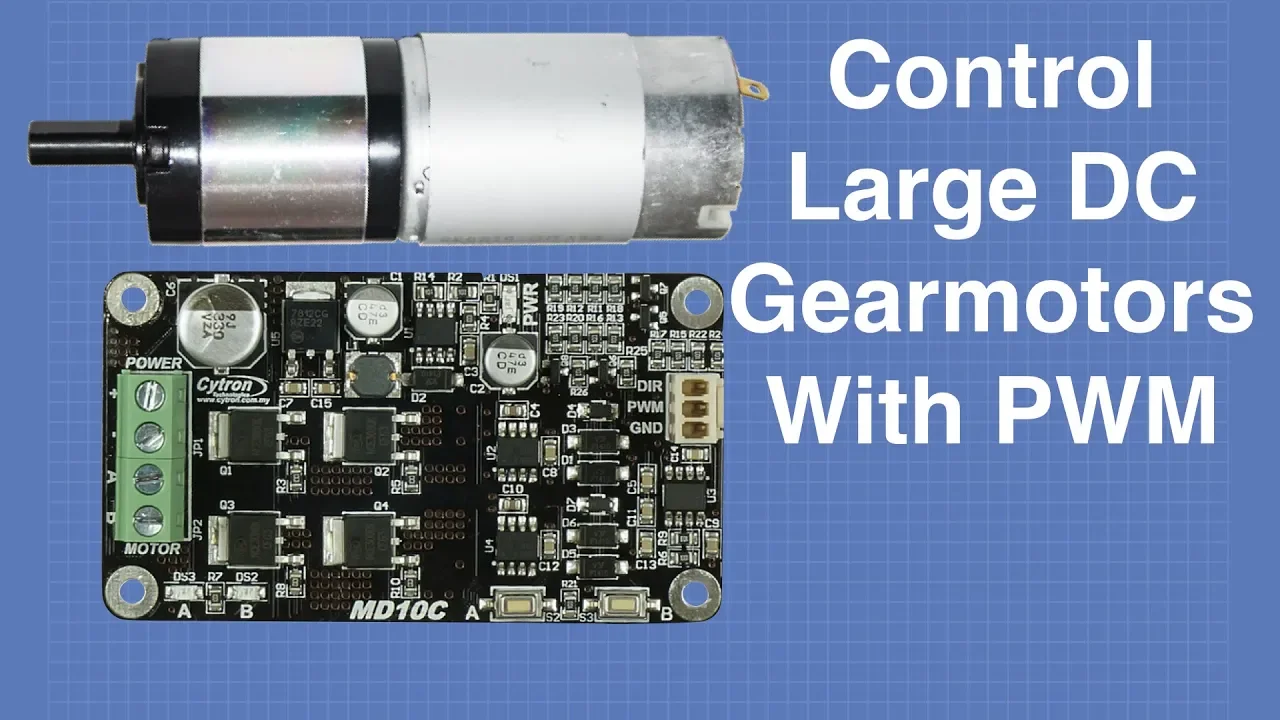
Using mapped analog inputs to control more complex actuators, such as Servo Motors and DC Motors via Pulse Width Modulation (PWM).
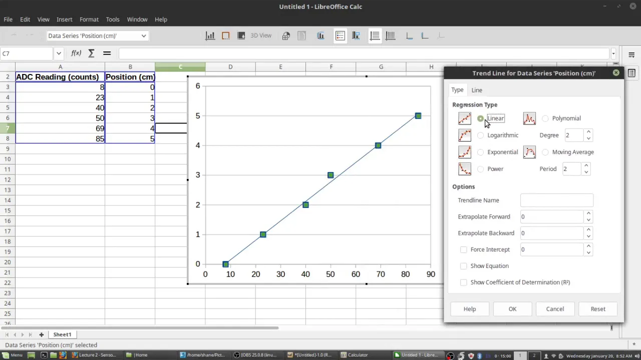
Sensor calibration techniques, learning how to map raw ADC (Analog-to-Digital Converter) values into real-world physical units (e.g., degrees Celsius or Lux).
Transitioning from analog sensors to digital-interface sensors that communicate using I2C or SPI protocols.
682.4K views4Klikes18:17Original Release: 2011-01-24
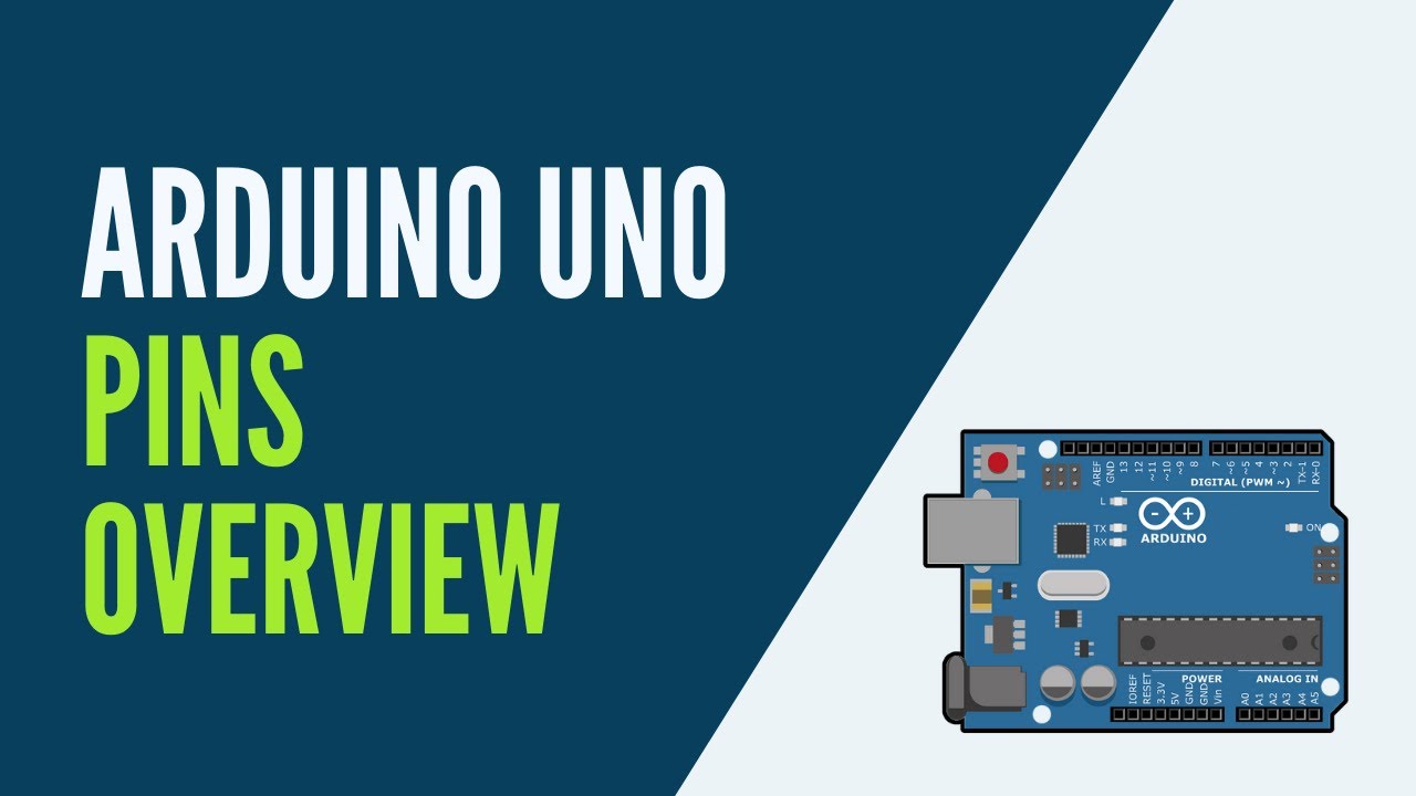
[Music] [Music] [Applause] [Music] hey everyone Jeremy Blum here with ar tutorial number four we're on a roll here today we're going to be talking about analog inputs to the Ard you know I'm going to talk about setting a reference level for the analog voltage taking an analog voltage in from either a pre-made sensor or building one yourself using a variable resistor and a voltage divider which is something we talked about last week and then we'll talk about mapping those values to different values in the uino programming language using it to control LED brightness which is an analog output and a few other applications so let's get started let's talk a little bit about how analog inputs are set up on the Arduino boards here I have the Uno the Mega 2560 and the Nano boards all these allow for analog input options and on all arduinos there is a 10bit analog digital converter that allows you to convert from ground up to the input voltage of the Arduino usually 5 volts to a value from zero to 1023 that means you have 1,24 bits of resolution or 2 to the 10th power hence why it's called 10 bit resolution if you want to learn a little bit more about how analog digital converters work please watch my techbits episode on analog and digital signals you can set the reference voltage that you use for the analog inputs on all these Arduino boards by default it's set to 5 volts or 3.3 volts on 3.3 volt aoo boards but here we'll just be walking working with the default 5vt boards you can also set it to an in internal 1.1 volt reference although that's not available on the mega and on the mega you can use different command set it to 1.1 volts or 2.56 volts as a reference you can also select your own voltage reference by setting it to an external value which you input into an analog pin on the uino here we can see the analog reference pin I was talking about you might want to consider using an external analog reference if you're only using sensors that go from 0 to 3.3 volts on a 5volt Arduino the reason for this is that the values from 3.3 volts up to 5 volts if you use the default 5vt reference will basically be excluded and you'll be getting less resolution than you potentially could using external voltage reference allows you to eliminate that problem down here on the bottom we can see the analog inputs a0 through A5 there's six inputs available on the Arduino Uno if we look now at the mega the mega has many more analog inputs available all these right here uh analog input 0 through 15 so there's 16 analog inputs available on the mega and if we look at the Nano board we can see that there are actually eight analog inputs available on here for our first sensor let's use a simple photo resistor photo resistors simply decrease their resistance as the ambient light in the room increases as I decrease the light in the room the resistance will increase so if we hook this up in a voltage divider circuit with a fixed resistor we can essentially feed into the Arduino a voltage that varies with light in the room so let's hook that up using this schematic here's our assembled circuit just like in the schematic we have a photo resistor connected between Vols and a 10K resistor the 10K resistor then goes to ground and at the junction between the two of them we take a wire out and go to analog input zero on the uino this is just like our voltage divider setup that we worked on in the last episode now let's program this to show us the values from the photo resistor as we change light in the room note that you can change the position of the photo resistor and the fixed resistor and the values on the computer will inverse let's write a quick program that will show us the value of this sensor so first we'll need to Define our input pins we'll call it sense pin that's going to be equal to analog input on pin zero now we always want to do our setup function and in here we don't need to Define as an input pin because it's set to that as default we can Define the analog reference as default that's because we're going from 0 to 5 Vols but again this line isn't necessary it will do this by default but I'll just put in here for complete coverage and we'll want to print this to the screen so let's set up our serial connection like we did last time and the 9600 just means the speed at which we're communicating with the computer 9600 bot is a pretty common value that you use all right and in our Loop all we're going to do is read the sensor and then print it to the screen so serial do print line just like last time analog read and the sensor pin sense pin make sure we close our parentheses and we don't want to spit out values constantly so we'll just put a delay in there of a half second that should be good all right let's see how this works out so we can see in ambient light we're getting a value of about 950 and as I put my hand over the sensor we can see that drops down if I cover it completely we go on to about 750 is 770 okay great but that's only giving us a range of 200 out of a potential range of 1,024 why is that well it's partially because of the resistors that we've chosen uh and the inherent fact that you're going to lose some values by using a voltage divider which is fine we don't need the full 1024 resolution you can overcome this by setting up an op amp and doing a few other things but it's not really that important to us if we want we can try to change the resistor to a 1K resistor and see how that changes it now we've got a 1K resistor in the circuit instead of a 10K resistor and we can say it's changed the values now ambient light is closer to around 570 and if I put my hand over it drops down to about 200 so that range is a little bit better uh not by much and you can keep messing with the resistor values until you get a value where you where you're happy but in reality this amount of range is fine for what we want to do we just saw that a value of around 900 is ambient Lighting in the room so let's make a simple NightLight now if the value goes below 800 we'll turn on an LED that will illuminate the room so all I've done here is added an LED to our circuit with our our 150 Ohm resistor same as we used last time and I've hooked it into pin N9 on the Arduino so uh let's go program that all right the first thing we'll have to do is to uh add our LED pin here and that's going to be pin n next up we have to set that pin as an output because defaults to an input so let's make the LED an output and we can get rid of the uh serial communication we're not going to use that anymore okay down in our Loop let's start by getting the value from the sensor and saving it to a variable so we'll make a new variable called Val pretty standard name do an analog read of the sense pin we don't need this one we don't need either of these anymore right and then if the value is less than 800 we'll do something so we'll use an if statement which checks the value so if the value is less than 800 we will do a digital right to the LED pin and turn it on otherwise if it's a greater than 800 let's make sure we turn it off digital right LED pin low which will turn it off and that's it so let's see how this works okay great we put our hand over it and the LED turns on just like we wanted to when it gets too dark in the room we'll have a nightlight now now you don't have to be afraid of monsters in your closet now let's make our NightLight a little bit more adaptive we'll have it change brightness based on the brightness in the room as the room gets darker the LED will get brighter to illuminate the room better we're going to need to do a few things to do this first off we need to map our value so there's a function in Arduino called map and map takes takes in an the original value Val in this case and values to map it to so the reason we do this is because our value for an analog input can range from anywhere from 0 to 1023 whereas analog output what we'll be using to change the brightness of the LED is only 0 to 255 additionally we want an inverse relationship as the value from the light sensor increases we want the value on the LED to decrease and vice versa so the map function will allow us to do that Val is the function we want to map and let's say we'll set 750 as the minimum and 900 as the maximum and that'll map to 255 and zero and we'll set that new value um equal to LED level so precisely what this is doing is it's taking in Val from the sense pin the value of 750 gets converted to 255 the value of 900 gets converted to zero anything in between scales proportionally so as the value increases from 750 to 900 this value will decrease or LED level will decrease from 255 down to zero which we can then feed into our led to change its brightness we want to do one more thing though it's to check for values outside of 750 or 900 if it's less than 750 or greater than 900 we want to set it equal to those values so that we're not dealing with anything greater than or greater than 255 or less than zero because the analog output won't know how to handle that correctly so we'll use one more function and we'll reset our valve first using constraint constraint is another arino function that takes in a value and then sets minimum of Maximum values so we'll set it to the same value 750 and 900 now what this does is takes the value from our sense pin if it's less than 750 it resets it to 750 if it's greater than 900 it sets it up to 900 100 now we only have to worry about values between these two which means these values will always be between 2505 and 0 just as we want them to now we can get rid of this and just use analog right to set the brightness of the led directly analog right LED pin and we'll Now set it to LED level awesome let's see how that works okay so the LED starts off like we expected to and as my move my hand closer we see the LED incrementally gets brighter until it's at full brightness when I have the sensor in complete darkness and it scales back just the same way perfect we now have an adaptable NightLight naturally photo resistors aren't the only kind of variable resistors that you can use in a circuit like this here I have a thermister which varies its resistance with temperature as I hold on to it you can see that the value drops from 460 down down to about 440 so this is actually working in the opposite direction of the photo resistor if we wanted it to increment the values in the same direction as the other one we could swap it with the resistor another thing to experiment with is using different resistor values if you look at the voltage divider equation that I showed you in the last episode you'll see how setting this resistor will affect the range that you get the analog readings on and then of course you can also use opamps to scale the readings up so you get a better resolution but we won't cover that in this episode of course you don't always actually have to build your own sensor you can often buy pre-assembled sensors that are designed to Output at a certain voltage so you don't have to worry about scaling them or adding a voltage divider circuit or anything like that this is an example of one this is an infrared distance sensor it uses an infrared emitter and receiver to bounce infared light off an object and detect the distance to it all sensors that come like this will usually have three wires a voltage wire a ground wire and a sense wire the red wire we give it 5 volts ground get connected to ground of course and then the yellow wire returns a value between 0 and 5 volts that we can feed into the analog digital converter in the Arduino and use it to measure a distance value you'll often notice that these kinds of sensors will give you broader range because they've already designed it to operate on the whole 0 to 5 Volt range you can also buy these sensors in 3.3 volt iterations and other voltage versions so if we look at the screen now as I move my hand closer and closer you can see that the value slowly increases from about 5050 all the way up to about 600 something let's wrap up today's tutorial with our first little project this project will combine the infed distance sensor and the photo diode that we use today to make an emergency lighting system in the event that a room is dark detected by the photo diode and movement is detected by looking at values from the infared distance sensor we'll turn on our emergency lighting system in this case an LED although you could easily hook this up through a relay to control a more powerful bulb a lot the code will be using to make this system work as very similar to what we had before there's only a few modifications that we need to make to put everything in place the first thing is is we're now using two analog inputs analog input zero and analog input one zero is connected to the distance detector or in this case a motion detector as we're using it and analog input one is connected to the photo diode which I'm calling light pin we still have an LED connected to pin 9 next up we're going to need to make two varials to keep track of the distance what we'll do is every time through the loop we'll keep track we'll look at what the distance is from the infrared distance sensor and compare it to what the distance was last time if it changes significantly from the previous detected value we can assume that something has passed in front of the infrared distance detector and assume that movement has occurred so we'll use these two variables to track that in the loop our threshold defined by int thresh we I've set it about 200 this is basically the value for which it's looking for deviation amount between the last distance and the current distance you can find- tune this to make the system as sensitive or as insensitive as you want I found that 200 works pretty well setup is the same we just have to configure LED pin as an output everything else is defaulted and uh here's our Loop so first off we're going to read our light value in from the photo dial using analog read just like we did before and we'll read in our current distance from analog read motion pin note that here I have to Define light Val as an INT because this is the first time I'm using it current distance I've already defined as an INT up here so I don't need to use the integer term again the next thing we're going to do is look if everything meets our conditions so this if statement will check if the threshold has been exceeded and if the light value is less than a value of 800 so how are we doing that let's break it down there's two parts here the part in this set of parentheses and the part checking for the light value those two parts are separated by double ENT which is a logic and that means if both the contents of this parenthesis are true and the and this is true right here then we'll execute the if statement which turns the LED on for 1 second if we look more specifically into this part of the if statement we can see that we're checking for our thresholds these double pipes indicate a logic or so either this or this has to be true for this entire part of the if statement to be validated as true the first part before the double pipes says current distance is greater than the last distance plus the threshold so if our threshold is 200 and our pre previous distance was 300 then if current distance is more than 500 then this will evaluate to True alternatively it'll evaluate to true if the last distance uh was something like 500 and then that minus the threshold of 200 is 300 so if current distance was less than 300 that would also indicate a significant change and that would also evaluate this to true so if all that's if one of these is true and then this is true also then we'll digital write the LED to high and turning it on leave it on for one second to make sure people have enough time to find their way it'll stay on if it continues to detect movement otherwise we'll turn the LED back off and then the last thing we have to do is set last distance equal to current distance so that the next time through the loop we can compare the distance that we used this time through the loop with the new distance so if I just put my finger over the photo diode or I just make some motion the L want turn on but if the room is both dark and motion is detected the LED will turn on for a second and help anyone who's roaming through the dark find where they need to go thanks for watching this episode of my artner tutorial series if you have any questions or comments or if you want to watch the other videos in this series you can do so on my YouTube channel S14 on my blog Jeremy blum.com or over at the element4 Arduino group I hope you guys enjoy this and I'll see you guys next week thanks to element 14 for helping me to sponsor this video series they were kind enough to provide a lot of the materials that I'll be using to create these tutorials feel free to go visit their website at element14.com check out their Community which is is a great place to talk with people about Electronics the Arduino and basically anything else engineering related and they also have a store where you can buy a lot of the parts that we'll be using in these videos
Up Next
15:49
Controlling NEMA17 Stepper with A4988 Driver and Arduino
@techathome
3.2K views•2025-12-24

12:54
Triumph of Orthodoxy Icon: Byzantine Art & History Explained
@BenCallan
2.1K views•2024-08-06

14:31
Getting Started with Arduino: Complete Beginner's Tutorial
@sciguy14
2.6M views•2011-01-02

1:42
Game of Thrones Opening Credits: A Cinematic Analysis
@gameofthrones
46.3M views•2011-04-18
Related Study Plans & Knowledge Roadmaps
Structured learning paths in General & Interdisciplinary Studies
general-studies
Elevator Engineering: History, Physics & Cities
01From Hoists to Safety Brakes: The Dawn of Vertical Lift
02Hydraulic vs. Traction: The Engineering Physics of Elevators
03Modern Speed, Safety, and Algorithms
+ 2 more learning modules
12h5 modules
Explore Roadmap
general-studies
Rubber: Material Science, History & Geopolitics
01Origins of Natural Rubber & Mesoamerican History
02The Chemistry of Natural Rubber & Vulcanization
03The Geopolitics of the Rubber Boom & Colonization
+ 2 more learning modules
12h5 modules
Explore Roadmap
general-studies
Containerization: Evolution, Logistics & Trade
01Ancient Trade & Bulk Cargo: Amphorae to Barrels
02The Industrial Revolution & Cardboard Packaging
03The Containerization Revolution: Malcom McLean
+ 2 more learning modules
12h5 modules
Explore Roadmap
general-studies
Textile Tech: Evolution, Labor & Global Impact
01Pre-Industrial Textiles: Handloom & Cottage Industry
02Mechanization: The Spinning Jenny to the Power Loom
03The Factory System & Global Labor Transformation
+ 2 more learning modules
10h5 modules
Explore Roadmap