










![🔥[FA-DUINO#33] 산업용 아두이노(arduino)와 TB6600으로 스탭모터(NEMA17) 제어해보기!(1)](https://i.ytimg.com/vi/iMD2FIcQl8c/maxresdefault.jpg)




This tutorial demonstrates how to control a NEMA17 stepper motor using an A4988 driver board and Arduino. The A4988 driver has key pins: VDD/GND for 3-5V power, VOUT/GND for 8-35V motor power, motor phase pins (1A, 1B, 2A, 2B), ENABLE (active low), MS1-MS3 for microstepping mode selection, RESET (active low), SLEEP (active low), STEP for generating motor pulses, and DIR for direction control. The Arduino code declares pins, sets microstepping mode (e.g., full step with all MS pins low), sets direction, and generates pulses on the STEP pin to rotate the motor. Speed is controlled by adjusting the delay between pulses, and direction is reversed by changing the DIR pin state.
Controlling NEMA17 Stepper with A4988 Driver and Arduino
Added:Basic Arduino programming concepts, including digital I/O operations, control loops, and basic sketch structure (setup and loop functions).
Fundamental electronic circuit principles, specifically understanding voltage, current limits, and why microcontrollers cannot directly power high-current motors.
The basic operating theory of stepper motors, including how bipolar stepper coils are structured and the concept of step angles.
How to use a breadboard and read basic electrical schematics to safely connect external components.
Configuring microstepping on the A4988 driver using the physical MS1, MS2, and MS3 resolution pins to achieve smoother motion.
Calibrating the motor current limit by measuring and adjusting the reference voltage (Vref) via the onboard potentiometer of the A4988.
Transitioning to advanced Arduino libraries, such as AccelStepper, to handle acceleration, deceleration, and multi-axis motor control without blocking code.
Integrating input sensors, such as limit switches (endstops) or rotary encoders, for homing routines and closed-loop position verification.
Applying these control concepts to complex projects like CNC machines, 3D printers, or automated camera sliders.
3.2K views84likes15:49Original Release: 2025-12-24
[Music] [Music] Hi guys, welcome back to 69th part of the audio tutorials.
In today's video, we'll see how to use Nema 17 stepper motor and A4988 driver board with Arduino.
In one of our previous tutorial, we had already worked on the small stepper motor 28 BYJ48 with ULN 20003 driver board.
Additionally, I had covered the construction of the stepper motor, basic working principle and different modes of operations like fo mode, full step and half stepping.
So I would recommend you guys to watch that video and get the concepts clear so that you can follow this particular video in a better way.
Today we'll mainly concentrate on the practical part.
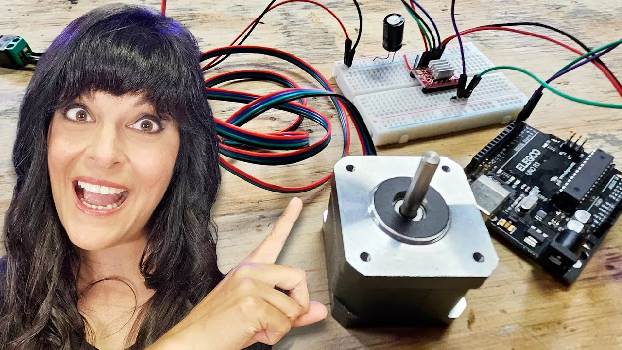
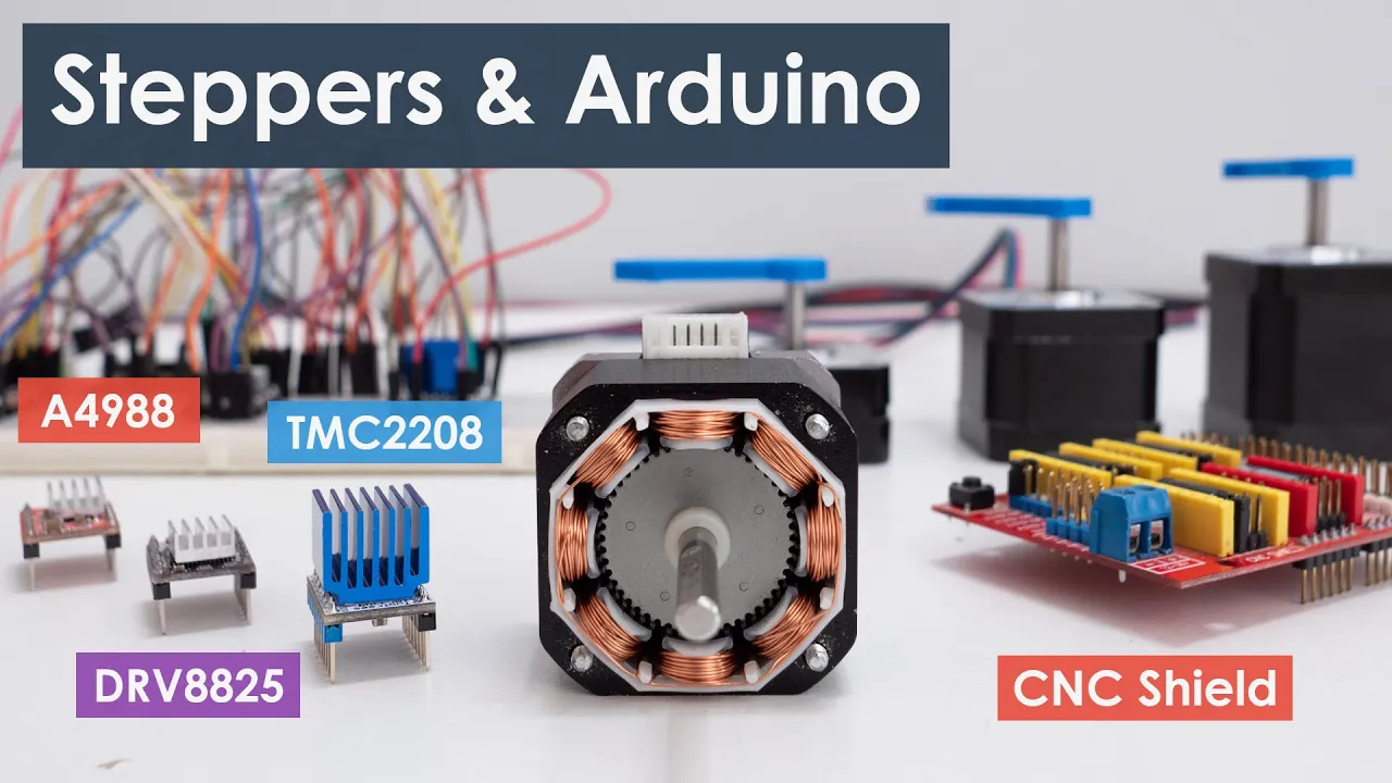
The components you need for this tutorial are Arduino board 17 stepper motor. I have the 7.2 kg cm torque model but you can go with any type. For controlling the motor, I'll go with A4988 driver board.
As a power supply for this motor, I'll use 11.1 volt 3 cell lipo battery.
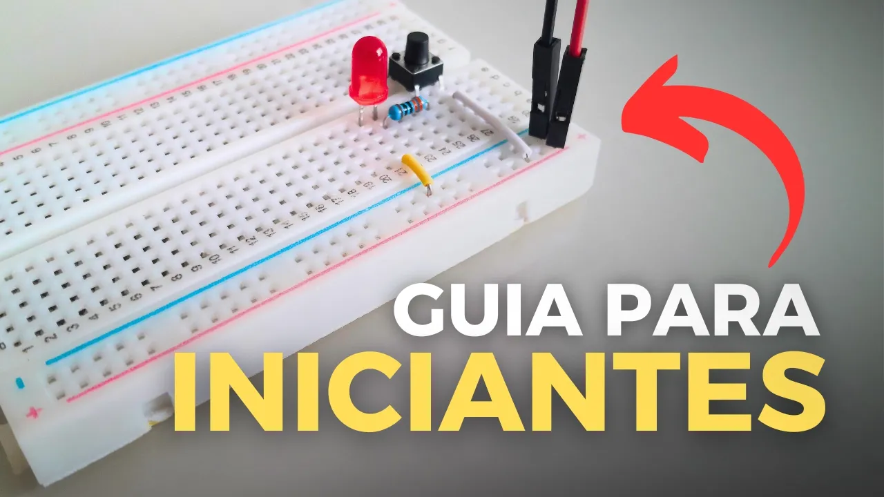
For easy connections, breadboard and jumper wires.
I purchased all these project components from flyrobo.in.
They have very huge collection of components and the prices are also reasonable compared to other platforms.
Make sure you explore their products. I leave the link in the description box.
Before we get into the circuit and the code, we need to get some things clear on the motor and the driver.
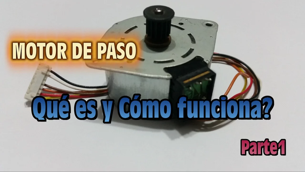
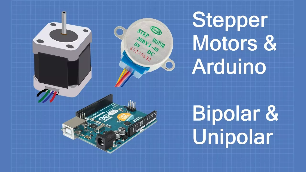
This Nema 17 motor contains two coils and four wires.
So we have to identify the end points of each coil for further connections. So I'm using the continuity test on the multimeter to identify the coil ends.
These two belongs to first coil and this for the second coil.
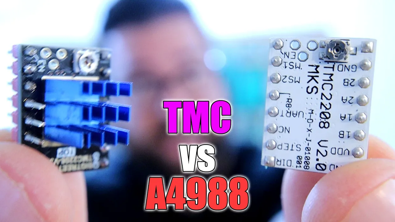
Moving further, we have to understand the pin outs of A4988 driver board.
These are the pin numbers we can consider for reference.
Starting from one on the left top to 16 on the right top.
Pin 10 and 9 are WDD and ground. These pins are used to supply power to the internal chip operation. And this can be from 3 volts to 5 volts.
Pins 16 and 15 are VOD and ground. And using these pins, you can supply power to the stepper motor. And this can be from 8 volts to 35 volts.
Pins 11, 12, 13, and 14 are 1 B, 1 A, 2 A, and 2 B. These directly connects to the phase wires of the stepper motor.
On the left side, pin one is enabled, which is used to enable or disable the driver board.
It's an active low pin. By pulling it low, the driver will get enabled.
By default, this pin will be internally pulled to low state. So, if you want to disable, you can make it high.
So next pin 2 3 4 are MS1, MS2 and MS3.
These are micro stepping pins which are used to select the different operation mode of the stepper motor. This is the reference table you can consider by selecting the respective combination of these values. You can run the motor in different modes based on your requirements.
If you want to understand more on this full step, half step, 1x4 step and so on, you can refer our previous tutorial video. I'll also leave the link in the description box.
Further, we have reset pin on pin five, which is also active low. If you pull this pin to low state, the driver gets reset and the motor goes to initial position.
For normal operation to avoid this reset, we have to externally pull this pin to logic high state.
On pin six, we have sleep again active low pin. By pulling this low, the driver board goes into power saving mode. In order to avoid this, internally this pin is pulled to high state.
So at last we have two control pins step pin on seven and this is the main input for running the motor.
If we give high signal on this pin the motor moves by one step.
So finally the direction pin on 8 is required for controlling the direction of the motor. By setting this pin to high the motor rotates in the clockwise direction.
and it changes to anticlockwise by making this pin to low.
With this, I hope the pin details are clear.
With this information, we'll move on to the connections.
First, I'll take the 5 volts and ground from the Ardino board onto the breadboard.
This line will be positive and this is negative.
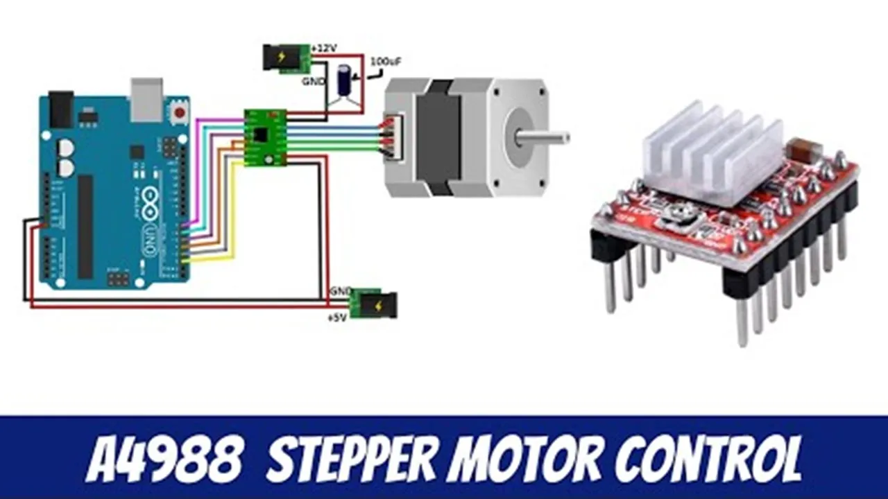
I'll place the driver on the breadboard with the trimming potentiometer facing the bottom side on the right. Bottom two pins WDD and ground goes to Ardino 5 volts and ground on the breadboard on the motor. These two for first coil and these two for the second one.
The end points of first coil goes to 2B and 2 A and the end points of second coil connected to 1 A and 1 B.
The top pins VOT and ground I'll connect later to 11.1 volt power supply.
Next, the step pin goes to ordino digital pin 2 and the direction pin to digital pin 3.
The sleep pin will be already high which is taken care internally in the circuit.
But the reset pin we have to externally make it high or you can directly connect with the sleep pin.
Micro stepping pins MS1, MS2 and MS3.
Connects to Arduino digital pins 4, 5, and 6.
This is all about the connections.
If you have any confusions, you can download the circuit diagram from the link in the description box.
Moving on to the coding part.
First I'll start declaring all the pins we have connected at the top in the declaration with int data type. So first is the step pin connected on pin two direction pin on three and further we have three pins for microep selection. MS1 pin 4 MS25 and MS3 on six. So in the setup function we'll set modes of all the pins as output with pin mode function.
This is two and this is three.
So next we have to set the values for the micro stripep selection pins.
We'll start with the default one which is full step mode.
So as per this reference we have to set all the three pins to low in order to use the full stepping mode. This we can do it in the setup function itself since it's one time. I'll use digital right MS1 low. I'll copy the same.
This will be MS2 and three. So all pins are low as per this. So we will get the full stepping mode.
Done with the setup function. We'll move on to the loop.
So very first we have to set the direction control pin using digital right function direction pin.
So we'll start with a high value or one and see which direction our motor rotates.
So the last part is to generate a pulse.
Every pulse on the step pin makes the motor to move by one step. So if you want the motor to keep running continuously, we can generate the pulses inside this loop function. So I'll use digital right step pin high some delay.
Instead of delay we can also use delay microconds so that we can get smaller values.
Start with 700 microconds.
So I'll copy the same and make it low. So with this we get one pulse which makes motor to move 1.8° as per this data sheet.
So this pulses in a loop will make our motor running continuously. We can also modify this delay values to control the speed. For now, I'll upload this code and show the results.
So, I'm connecting this 12vt supply now.
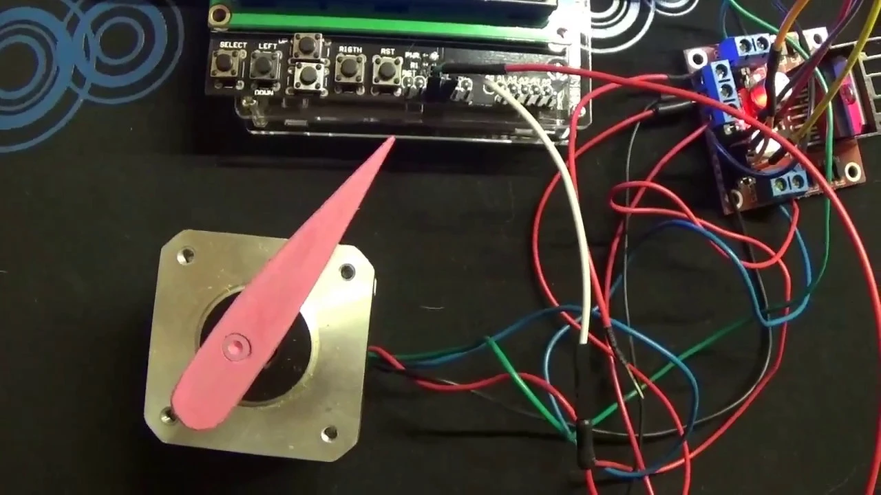
So, as you can see, the motor is rotating with full stepping mode and in the backward direction.
So now in order to change the direction simply reverse the value on the direction pin. So it was high I'll make it low and upload the code.
As we can see the motor started rotating in the forward direction.
So this is on the direction for controlling the speed. Now I have 700 microconds. I'll make it 1,200.
So with increasing the delay the motor speed will reduce.
So the speed has reduced slightly.
I can still reduce the speed by giving larger values like 2,000 microconds.
From this we can see the speed has reduced.
So last part on the microep selection.
So we have full stepping mode now.
So in order to make it 1x4 step we have to make low, high and low.
So this I'll change it in the setup function.
Low, high and low.
So this is how 1x4 step looks.
So in the same way you can also try other modes of operation by changing the combination of these three pins.
So this is how you can run the stepper motor, control the direction and operate on different modes using A4988 driver board.
I hope this video will help you lot in your projects.
If you have any doubts, let me know in the comment section below and make sure to check out the other videos from the playlist.
Thank you for watching. We'll be back in the next one.
Up Next

16:20
Mastering Single-Axis Solar Tracking Logic Circuits in Stationeers
@Splitsie
73.9K views•2020-10-19

12:54
Triumph of Orthodoxy Icon: Byzantine Art & History Explained
@BenCallan
2.1K views•2024-08-06

9:49
FastAPI vs Flask vs Django: Choosing the Right Python Web Framework
@TechWithTim
302.5K views•2024-05-26

1:42
Game of Thrones Opening Credits: A Cinematic Analysis
@gameofthrones
46.3M views•2011-04-18
Related Study Plans & Knowledge Roadmaps
Structured learning paths in General & Interdisciplinary Studies
general-studies
Elevator Engineering: History, Physics & Cities
01From Hoists to Safety Brakes: The Dawn of Vertical Lift
02Hydraulic vs. Traction: The Engineering Physics of Elevators
03Modern Speed, Safety, and Algorithms
+ 2 more learning modules
12h5 modules
Explore Roadmap
general-studies
Rubber: Material Science, History & Geopolitics
01Origins of Natural Rubber & Mesoamerican History
02The Chemistry of Natural Rubber & Vulcanization
03The Geopolitics of the Rubber Boom & Colonization
+ 2 more learning modules
12h5 modules
Explore Roadmap
general-studies
Containerization: Evolution, Logistics & Trade
01Ancient Trade & Bulk Cargo: Amphorae to Barrels
02The Industrial Revolution & Cardboard Packaging
03The Containerization Revolution: Malcom McLean
+ 2 more learning modules
12h5 modules
Explore Roadmap
general-studies
Textile Tech: Evolution, Labor & Global Impact
01Pre-Industrial Textiles: Handloom & Cottage Industry
02Mechanization: The Spinning Jenny to the Power Loom
03The Factory System & Global Labor Transformation
+ 2 more learning modules
10h5 modules
Explore Roadmap