
























Faraday's Law states that an electromotive force (EMF) is induced in a coil when the magnetic flux through it changes, with the induced EMF proportional to the rate of change of magnetic flux (EMF = -N × ΔΦ/Δt). Lenz's Law specifies that the induced current flows in a direction that opposes the change in magnetic flux causing it. Magnetic flux (Φ) equals the product of magnetic field strength (B), area (A), and the cosine of the angle between the field and the normal to the surface (Φ = BAcosθ). The induced EMF can also be calculated for a moving conductor as EMF = Blv, where B is the magnetic field, l is the length of the conductor, and v is its velocity. Transformers operate on these principles, with the voltage ratio equal to the turns ratio (VS/VP = NS/NP), and power is conserved assuming ideal efficiency (VP × IP = VS × IS).
Faraday's & Lenz's Law: Electromagnetic Induction Explained
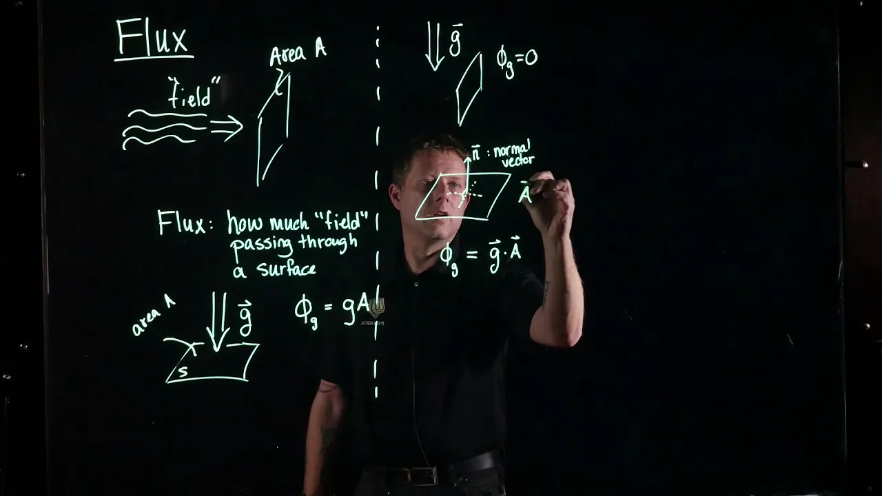
Added:in this video we're going to talk about Faraday's law of electromagnetic induction and also lens law so let's say if we have a coil of wire and if we have a magnet what's going to happen if we move the magnet into the coil if we move the magnet into the coil there's going to be a current that's generated in the coil let's say the coil is connected to some meter As you move the magnet into the coil a current will be generated and this current is going to move in the counterclockwise Direction the magnet produces a magnetic field which goes into the page as X represents into the page and a circle represents out of the page now what's going to happen let's say if we have the same coil but this time if we move the magnet away from the coil if we move it away from the coil then the direction of the current will reverse the current will no longer flow in a counterclockwise Direction but it's going to flow clockwise so if you move the magnet into the coil the current is going to flow counterclockwise if you move it away from the coil it will change direction now what about changing the speed let's say if we move the magnet slowly if you move the magnet slowly into the coil the induced current will be very small but if you move the magnet quickly into the coil the induced current will be larger if you don't move the magnetic field excuse me if you don't move the magnet into the coil there will be no induced current so it also depends on the speed at which the magnet moves into or out of the coil the greater the speed then the greater the induced current will be now there are other ways to inducing the current and it's not only just moving the magnet into or out of the coil if you change the area of the coil let's say if you stretch it or bend it that will induce a current also if you change the angle if you turn the coil relative to the magnetic field in produced by the magnet if you change the angle an induced current will be created now there's an equation that you need to know this equ equation is the magnetic flux the magnetic flux is equal to the product of the magnetic field times the area time cosine of the angle and the unit for magnetic flux is the Weber we b r one Weber is basically one Tesla * 1 s met the for magnetic field is Tesla T and the unit for area is square met so when you multiply these two you get the unit of Webers now we know that there's going to be an induced current anytime the magnetic field is changing if the area of the coil is changing or if the angle is changing as well and so the induced EMF or the induced current is dependent on the rate of change of of the flux because it also depends on how fast you moving the bar magnet into or out of the coil if you move it slowly the induced current will be small if the bar magnet is moved quickly into the um coil the induced current will be larger so the induced EMF and therefore the induced current is dependent on the rate of change of the magnetic flux which we'll talk about soon so let's say if we have a surface now let's draw the normal line to the surface which we'll call n and let's say if the magnetic field is perpendicular to the normal line which means it's parallel to the plane of the surface or to the face of the coil the angle Theta is between the normal line and the magnetic field so the angle is 90 Co sin 90 is equal to Z so therefore the electric flux will be zero so if the magnetic field doesn't pass through the face of the coil if it's parallel to the face of the coil there will be no electric flux and if there's no electric flux there's no induced EMF now let's say if it's neither parallel or perpendicular to the normal line Theta is here it's the angle between a normal line and B so in this situation the electric flux is simply ba a cosine Theta now the last case is if the magnetic field is parallel to the normal line so the magnetic field is perpendicular to the plane of the coil so in this case the angle Theta is z and cosine 0 is equal to 1 so the electric flux is simply equal to B * a the electric flux is greatest when the magnetic field is parallel to the normal line or when it's perpendicular to the face of the coil that's when you're going to have the maximum electric flux and it's at a minimum if the magnetic field is parallel to the face of the coil now the induced EMF is equal to m which relates to the number of coils by the way if you increase the number of coils let's say if you have 10 Loops compared to one Loop the induced EMF and therefore the induced current will be larger when you move the bar magnet into the coil so the more Loops you have the greater the induced current will be so the induced EMF is equal to n time the change in the electric flux divided by the change in time this equation is associated with Faraday's law of induction so basically it states that the induced EMF is proportional to the rate of change of the electric flux and the electric flux is ba a cosine Theta so if the magnetic field B changes or if the area changes or if the angle changes there's going to be an induced EMF generated now the induce EMF you can treat it like voltage voltage and EMF they both have the same unit VT so if V is equal to IR then the induced EMF is equal to IR so if you know the induced EMF and if you know the resistance you can therefore calculate the induced current so if the induced EMF increases the induced current will increase because the resistance of the circuit should remain the same now now before we go into lenses law let's review a few basic things so let's say if we have a long straight wire with a current traveling north anytime you have a current inside a conductor it will create a magnetic field for this particular picture the magnetic field will enter the page on the right side and it's going to leave the page or it's going to travel out of the page on the left side so out of the page is represented by a circle and into the page is represented by X now to figure this out you can use the right- hand rule so let's say if the pen is the conductor or the wire if you take your right hand and wrap it around a pen and you want your thumb to face the direction of the current the way your fingers curl around the pen is the direction of the magnetic field as it travels around the conductor so let's see if I can draw this I drawing's not the best so so here is the conductor and here's the person's hand wrapped around the conductor so you want your thumb to face the direction of the current and notice the way your hands curl around the wire it comes out of the page on the left side and it curls into the page on the right side and so that represents the direction of the magnetic field so I want you to remember this picture because we're going to use it a lot when when trying to figure out the direction of the induced current so this picture is based on the right hand rule now if the current is going in the opposite direction then the magnetic field will change as well so it's going to be going into the page on the left side and out of the page on the right side so everything's going to be reversed now lens's law states that the induc EMF always gives rise to a current whose magnetic field opposes the original change in flux so let's apply that to the coil of wire that we had in the beginning so let's take this bar magnet and let's move it into the coil and let's use lens's law to determine the direction of the induced current inside this coil now as we move the magnet into the coil the magnetic flux is an increasing or decreasing well first we need to find the direction of the magnetic field the magnetic field emanates away from the North Pole enters the South Pole so the magnetic field is going into the page that's the external magnetic field now the external magnetic field is increasing which means that the flux is also increasing if the flux increases the induced current will be directed in such a way to decrease the flux so if you try to increase the flux the induced current will oppose that change it's going to decrease it and if you try to decrease the flux the induced current will try to support it or increase it so it's always opposite to what you're trying to do so since the external magnetic field is increasing the induced current will create a magnetic field that will oppose the external magnetic field the external magnetic field is directed into the page so if it's if it's going to oppose it it has to be out of the page it has to be opposite to it so I'm going to represent that in blue so on the right it's going to be opposite to the magnetic field that is in the center of the loop and on the left it has to be X they can't be the same so on the right side it's going to look like this so if you take any segment of the wire on the inside of the loop it's going to have a magnetic field that opposes or it's opposite to the external magnetic field inside the loop don't focus on the outside part focus on the inside part of the loop now what is the direction of the current if we have a wire where the induced magnetic field is going into the page on the right side I mean out of the page on the right side but into the page on the left side so hopefully you remember those two pictures that we went over the induced current has to be going in this Direction that's the only way the magnetic field will be coming out of the page on the right side into the page on the left and you can use the right hand rule to figure this out so therefore what we have is a current traveling in the counterclockwise Direction now let's work on another example so let's say if we have a rectangular metal conductor which looks like this and we also have a magnetic field confined in this blue region and let's say the magnetic field is going uh into the page everywhere in this region what is the direction of the induced current if the conductor is moving into the magnetic field is the current traveling clockwise or counterclockwise in this uh rectangular Loop so feel free to pause the video and use the lens's law to figure this out now the magnetic field is not increased or decrease and it's constant however the area inside the rectangular Loop that is exposed to the magnetic field is increasing so therefore we could say that the magnetic flux is increasing and the induced current will be in such it's going to be in a direction where it's going to try to uh decrease the flux because the magnetic flux is increasing according to lens's law the induced current will try to decrease the flux and the only way to do that is to direct itself opposite to the magnetic field now the external magnetic field at the center of the loop is going into the page if the induced current is going to oppose it then the induced magnetic field has to be going out of the page at the center of the rectangular Loop so what you need to do now is select a segment of wire let's use this segment and on the right side it has to be going out of the page whatever we have here that's going to be the induced magnetic field at the center of the loop so if on the inside or at the center it's going out of the page then on the outside it's into the page now don't forget these two pictures anytime you have a segment of wire when the current is going up the induced magnetic field will be going out of the page on the right side into the page on the left I take that back it's into the page on the right side out of the page on the left and if the current is going down then it's out of the page on the right side into the page on the left using the right hand rule so what we have here is basically this picture so the current is going down on the left side which means it's traveling in the counterclockwise Direction and so that's the answer for the sake of practice let's work on another example so this time the loop is going to move away from the magnetic field the external magnetic field will be directed into the page again just like before and the loop is moving away from it go ahead and use lens's law to determine the direction of the current so the first thing we need to do is determine if the flux is increasing or decreasing now the external magnetic field is constant but the coil or the rectangular Loop is moving away from the magnetic field therefore the area that is exposed to the magnetic field is decreasing and so the flux is decreasing as the coil moves away from the magnetic field now if the magnetic flux is decreasing and induced current will be created in such a way to increase the flux if the flux is decreasing according to lens's law it wants to oppose the change in flux so it wants to increase the flux the only way to increase the flux is to support the magnetic field the external magnetic field is direct Ed into the page as we can see by the AES here and so in order for the induced current to support it it has to go in the same direction not the opposite direction as we did in the last example so it's going to be going into the page as well so let's choose a segment of wire that we should focus on let's choose this segment now at the center of the loop it's going to be going into the page which means on the right side it will be uh out of the page so using this information what is the direction of the current well anytime you have a segment of wire where on the right side if the magnetic field is going into the page and on the left side the induced magnetic field I keep mixing up on the right side it's going out of the page and on the left side into the page and this case using the right hand rule the current is going to travel down so if it's traveling down here then it's going to be to the left and on the left side it's going up and at the top it's going to the right so therefore it's traveling in a clockwise Direction which makes sense so as the coil moves into the magnetic field the current is traveling in the counterclockwise Direction and as in this example as it moves away from the magnetic field it's going to reverse traveling in a clockwise Direction so you have to be careful with every step hopefully these three examples gives you a good idea of the process that you have to use in order to determine the direction of the current let's work on a new example so let's say if we have a coil of wire and it's place inside a magnetic field and this is the external magnetic field which is directed everywhere into the page now let's say we uh take this coil and we shrink it we're going to make it smaller so we're going to decrease the area of the coil such that it looks like this determine the direction of the current inside that coil so because the area is decreasing the magnetic flux is decreasing as well now if the flux is decreasing according to lens's law the induced current will be in such a direction that it's going to try to oppose the change in flux if the flux is decreasing the induced current will try to increase the flux and anytime it tries to increase the flux that means that it's going to create an induc magnetic field that is in the same direction as the external magnetic field the external magnetic field is going into the page so therefore in order for the induced current to support the fail in magnetic field it has to be in the same direction so it has to be into the page as well so let's draw our small wire and let's choose a segment of the wire let's focus on the right side we can choose any segment but I like to choose a segment that looks like this because we know the two possibilities already if the current is going up we know that the magnetic field that is the magnetic field created by this current the induced magnetic field is going to be going into the page on the right side and out of the page on the left left side and if we reverse it let me draw this somewhere else if the current is going down then the magnetic field is going to be going into the page on the right side I mean out of the page on the right side into the page on the left X is into the page this dot is out of the page now going back to this the induced current has to be going into the page at the center so relative to this segment of wire the center is on the left side so there's going to be an x on the left side which means a DOT on the right side so these two look similar which means that they're current and that segment of Y is going down so therefore the current in this wire is traveling in the clockwise Direction and so that's the answer let's say if we have a wire and the current in this wire is increasing determine the direction of the induced current in the circular Y is it going to be clockwise or counterclockwise feel free to pause the video and use lens law to find out now if the current in a straight wire if it's increasing then that means the magnetic field is increasing which means the flux generated by that wire is increasing and that is the magnetic field that is produced by this wire that is in the center of this Loop that's going to increase which will increase the flux so therefore the induced current in the circular wire is going to create a flux that opposes the original flux so if the original flux is increasing according to lens's law the flux created by the induced current will try to decrease the increase in flux so it's going to opposite it's going to be opposite to it now if it's going to opposite then the magnetic fields have to be in the opposite direction not in the same direction so let's focus on the external magnetic field so using the right hand rule whenever you have a current going in the upward Direction the magnetic field is going to be going out of the page on the left side and into the page on the right side so it's going to be going in this general direction this is how it's going to look like now the coil of wire the circular coil is on the right side and the magnetic field generated by the straight y on the right side is X so the external magnetic field is into the page and at the location of the circular wire now because the induced current wants to oppose the increase in flux the induced magnetic field has to be opposite to the exter magnetic field so it has to be out of the page at the center let's use a different color let's use blue now let's focus on this segment so at the center or on the left side it has to be going out of the page and on the right side into the page so notice that we have the same direction on the left side we have a DOT on the right side we have an X therefore the current must be going up in that segment of wire which means that the current is traveling in the counterclockwise Direction so that's the answer now let's say if we have a wire and there's a current traveling towards the left and that current is decreasing and we have a circular wire below it what is the direction of the induced current in the circular wire go ahead pause the video use lens of law to figure it out so let's focus on the magnetic field created by the wire with the decrease in current if the currents going to the left if you take your hand and wrap it around a pen with your thumb pointing towards the left in the direction of the current you'll see that your fingers will curl into the page at the top and they're going to come out of the page below the pen so I'm not going to draw it but that's how it should look like so the external magnetic field is out of the page below the wire and that's what we want to focus on because that's where the uh circular wire is located it's below uh this wire now the flux is decreasing because the current is decreasing a decreasing current will produce a decrease in magnetic field and a decrease in magnetic field leads to a decrease in flux so according to lens's law the induced current will be directed in such a way that it's going to try to support the decrease in flux so if the flux is decreasing it's going to try to increase it it's going to oppose a change now anytime it tries to increase the flux it's trying to support the decrease magnetic field and anytime it wishes to support it the two magnetic fields have to be in the same direction now at the center the external magnetic field which is this one is directed out of the page and because the induced magnetic field has to be in the same direction as the external magnetic field because it wants to support it this one also has to be out of the page now let's focus on this segment of the wire so the induced magnetic field is out of the page and the center is on the left side so it's going to be out of the page on the left into the page on the right so therefore this will create a current that is going upward or if we focus on the left side instead of the right side the center is going to be out of the page the center is on the right side of that segment and then the left side is going to be going into the page and so the current has to be going down so really doesn't matter what you decide to focus on as we can see the current is traveling in the counterclockwise Direction and so that's the answer for this one now here's another example for you so let's say if we have a circular coil of wire which is attached to a battery and that's attached to a resistor and there's an open switch and inside that coil there is another coil of wire when the switch is closed what is the direction of the current and the coil of wire that is represented by the gray color so let's say it's a 6vt battery and we have a 3 Ohm resistor so right now the current is zero when the switch is open however once we close the switch the current will become two so it's going to go from zero to 2 amps so therefore the current is increasing which means that the flux is increasing and if the flux is increasing according to lens's law the induced current will create a flux that opposes the original change in flux the flux is increasing so the induced current will create a flux that will try to oppose the other one so it's going to be decreasing anytime the induced current creates a decrease in flux the external magnetic field and the induced magnetic field will have or will be in the opposite direction if the induced current creates an increasing flux it's going to try to support the F magnetic field and the external magnetic field and induced magnetic field will be in the same direction in that case but in this particular uh example since the flux is increasing the induced current will try to oppose the flux or decrease it so the exteral magnetic field and the induced magnetic field will be in opposite directions now we need to determine the direction of the external magnetic field that is the magnetic field created by the white circular wire so let's focus on this segment of the wire so we need to determine the direction of the current the current will Flow Away from the positive terminal towards the negative terminal so once the switch is closed the current will be going in the counterclockwise Direction so on the right side since the current's going up using the right hand rule it's going to be going out of the page on the left side into the page on the right side so that's the external magnetic field so at the center the external magnetic field is out of the page that's at the center of the gray Loop so that's what we're going to put here now because the induced current wants to oppose the increase in flux the external magnetic field and the induced magnetic field will be in opposite directions so the induced magnetic field will be going into the page at the center of the loop so I'm going to represent that in blue so let's focus on this segment of the wire so at the center which is to the right of that segment it's going into the page which means to the left it must be going out of the page and therefore it must be opposite to this one because the direction of the X and the dot actually no it's in the same direction because both cases the x is on the right side and the DOT is on the left side so therefore this must be going up so the current is traveling in the clockwise Direction so that's the direction of the induced current now let's work on some problems number one a single circular Loop of wire is perpendicular to a magnetic field which increases from 1.5 Tesla to 4.8 Tesla in 23 milliseconds part A calculate the change in magnetic flux so let's begin with that the change in flux is equal to the change in the magnetic field time the area time cosine of the angle now let's draw a picture so we have a single circular Loop and and here's the normal line which is perpendicular to the surface here's the uh radius and a magnetic field is perpendicular to the circular Loop which means that it's parallel to the normal line so the angle Theta is the angle between the normal line and a magnetic field therefore the angle is 0° and cosine of 0 is 1 so now we can calculate the change in electric flux so the change in B is going to be the final magnetic field which is 4.8 Tesla minus the initial magnetic field which is 1.5 Tesla the area is constant and the area is the area of a circle P pi r 2 the radius is 25 cm which is25 M squar and then times cosine of 0 we know cosine of 0 is one 25 s * pi that's 19635 and if you multiply that by the difference of 4.8 and 1.5 which is 3.3 this will give you the change in flux which is uh 648 and the unit for magnetic flux is the Weber which is uh Tesla times square meters so that's the answer for part A it's positive.
648 Part B what is the induced EMF to calculate the induced EMF we can use this formula it's n times the change in the flux divide by the change in time n is the number of loops and we have a single circular Loop so n is one the change in flux is 648 and the change in time the magnetic field increased from 1.5 to 4.8 Tesla in 23 milliseconds so that's Delta te but we need to convert milliseconds into seconds we could do so by dividing by th 23 divid by 100000 is 023 so 648 ID 023 that's about 28.7 volts so that's the induced EMF now the next thing we need to do is calculate the current the current is the induced EMF divided by the resistance so it's 28.7 volts divided by 20 ohms and this is equal to 1.41 amps and so that's the answer for part c number two the magnetic flux through a coil of wire containing 20 Loops changes from pos2 to3 Webers in 425 milliseconds what is the induc MF the induc MF is equal to n times the change in the electric flux I mean not the electric flux but the magnetic flux divided by the change in time so in this problem we have 20 Loops of wire the flux changes from 2 to minus 3 the Final flux is -3 the initial flux is pos2 so it's -3 minus pos2 now we need to convert milliseconds to seconds and we can divide it by th000 425 milliseconds is 425 seconds -3 - 2 is5 -20 * is positive 100 and if we divide that by 425 the induced EMF is equal to 235.000 volts now that we have the induced EMF we can calculate the resistance of the coil so eal I * R just as v = i * R and solving for r r is the induced EMF divided by the current so it's going to be 235.50 volts divided by a current of 5.12 amps and so the resistance is approximately 46 ohms now let's say that we wanted to calculate the power absorbed by the resistance of this coil how much power is dissipated in the coil power is equal to voltage times current or the induced EMF times the current so it's going to be 235.000 volts times a current of 5.2 amps so that's about 1,25 Watts number three a flexible rectangular coil of wire with 150 Loops is stretched in such a way that its Dimension changes from 5x 8 square cm to 7 by1 square cm in5 seconds in a magnetic field of 25 Tesla that is 30° relative to the plane of the coil calculate the induc EMF the induced EMF is equal to n time the change in electric flux divided by the change in time and the change in electric flux it's going to be the magnetic field which is constant times the area since the area is not constant we're going to multiply by the change in area times cosine Theta ID delta T now let's talk about cosine Theta so let's say this is the rectangular coil of wire and this is the normal line and this line is parallel to the plane of the coil and here is the magnetic field the magnetic field is 30° relative to the plane of the coil buta is the angle between a normal line and a magnetic field so Theta in this problem is 60 it's 90 minus 30 n is the number of Loops which is 150 the magnetic field is 2.5 rather 25 Tesla now the change in area the area of a rectangle is basically the length times the width but we need to convert cenim to met so we got to divide by 100 the change in area is going to be the final area minus the initial area the final area is 7 cm by 11 cm or 07 m time1 m that's the final area the initial area is 05 M time 08 M and then let's multiply by cosine of 60° and let's divide everything by5 seconds so let's calculate the change in area first 07 * minus 05 * 8 that's 0.37 or 3.7 * 10us 3 next multiply that by cosine 60 and then times 150 and time 25 so that's 6.
9375 and divided by5 seconds your final answer should be negative 46.2 volts so that's the answer to part A that is the indued EMF now let's move on to Part B so let's get rid of a few things how much energy in Jews was dissipated in the circuit if the total resistance is 100 ohms so before we can find the energy we need to calculate the power and before we can find that we need to find the current so let's find the current first the current is equal to the induced EMF divided by the resistance so it's - 4625 volts divided by 100 ohms now you really don't need to worry about the negative sign but you can keep it there if you want to so let's just ignore the negative sign for now so the current is going to be 4625 amps energy is going to be positive so we're going to make the final answer positive now that we have the current we could find a power dissipated by the circuit it's the voltage or the induc MF times the current so it's 46 rather 46.2 that's the induced EMF times the current which is 4625 and so that's going to be 2.39 Watts energy is equal to power multiplied by time one watt is onew per second so we have 21 39w per second and if we multiply by5 seconds we can see that the unit seconds will cancel given us the energy in Jews so the final answer is 3.21 Jew so that's how much energy is dissipated in a circuit so the circuit consume three 21 Jew within the 15 seconds in which the area was changing number four a rectangular coil of wire contains 25 Loops the angle between a normal line of the coil and the magnetic field changes from 70 to 30° in 85 milliseconds calculate the induc EMF so let's say this is the rectangular coil of wire and here is the normal line perpendicular to the surface so initially the magnetic field is at an angle of 70° relative to the normal line and then after some time the magnetic field let's call this B final and B initial well the magnetic field is constant but the angle changes so it's really Theta final and Theta initial but after some time the magnetic field is going to be 30° relative to normal line so that's the picture that we have in this problem how can we use this information to calculate the induced EMF by the way there's two ways the angle could change either the magnetic field is constant and the coil changes relative to the magnetic field or the coil is held in place and the magnetic field changes Direction relative to the coil now in this problem it really doesn't matter which one changes all we need to know is just the final angle and the initial angle the induced EMF is equal to Nega n times the change in flux divid by the change in time and the flux it's going to be b b is constant the area is constant but the angle changes so it's going to be the change in cosine Theta / delta T N the number of Loops is 25 the magnetic field B is three Tesla the area we need to convert centimeters to meters so it's going to be5 m times 20 M we have a rectangular surface so the area is simply the length times the width 15 * 20 and then multiply by the change and cosine the initial angle is 70 the final is 30 so final minus initial cosine 30 minus cosine 70 divided by the change in time which is U 085 seconds don't forget to divide 85 Mill seconds by a th000 to convert it to seconds now let's plug this in let's start with the cosine part first cosine 30 minus cosine 70 that's. 524 and make sure your calculator is in degree mode now let's multiply 0524 by5 time20 * 3 * 25 so that's going to be netive 1.179 and then divid by 85 so the induced EMF isga 13.87% so Faraday's law of electromagnetic induction is associated with this formula now let's say if we have a moving conductor that can slide freely along the metal rails and this conductor is moving with a speed V and a rectangular coil that it forms is perpendicular to the magnetic field the magnetic field is directed into the page and a rod has a length L how can we come up with an equation that will help us to calculate the magnitude of the induced EMF let's start with Faraday's law of induction the induced EMF is equal to n times the change in the magnetic flux divid by the change in time now as the rod moves the area that is exposed to magnetic field will increase so let's draw a new picture and let's say the rod is now in this area so notice that the flux is greater since the area exposed by the magnetic field contained in that coil is greater so this is going to move some distance a d and that distance is equal to the speed multiplied by the change in time so the increase in area is basically let me use a different color this region here represents the increase in area and the area of that region is basically the length times the width which is d so the change in area is L * D and D is basically the velocity times the change in time now going back to the first equation let's replace the flux with the magnetic field which is constant times the change in area and the angle is zero because the Mantic field is perpendicular to the plane of the coil it's parallel to the normal line which means the angle between the normal line and a magnetic field is zero and cosine of Z is one so we don't have to worry about the cosine part in this formula so we just have this now let's replace Delta a with LV delta T and by the way we only have a single Loop so n is equal to one so the induced EMF is going to be n or1 and since we're looking for the magnitude we don't have to worry about the negative sign so this going to be 1 * B and Delta a is l v delta T ID delta T and so we can cancel the change in time so therefore the induced EMF is equal to the strength of the magnetic field B times the length of the moving Rod l times the speed of the moving r v so it's blv now turns out that there's another way in which we could derive that same equation but first let's talk about the current in this circuit as the rod moves towards the right the area is increasing which means the flux is increasing by the way if you want to feel free to pause the video and use lens's law to determine the direction of the current in the moving Rod so because the rod is moving to the right the area increases and the flux increases so according to lens's law the induced current will be directed in such a way as to oppose the increase in flux so it's going to try to decrease the flux and since it's in opposition to it the external magnetic field which is directed into the page is going to be opposite to the induced magnetic field so if the external magnetic field is into the page the induced magnetic field is going to be out of the page so to the left of the rod which is the center of the coil the induced magnetic field will be out of the page which means to the right it's going to be into the page and so using the right hand rule the current has to be traveling in this direction electric current flows from a high potential to a low potential so from a positive side to a negative side that means the bottom of the conductor has a higher um electric potential and the top part has a lower electric potential current represents the flow of positive charge and so the electric field inside the conductor is in the same direction as the current so if you have a conductor with an electric field directed North any positive charges will fill a force that will accelerate in the direction of the electric field but in a metal the protons are not free to move the electrons are the electrons are the charge carriers the electrons will fill a force that will accelerate them opposite to the direction of the electric field and the electrons will move a distance L which is the length of the rod from one point to the other point so to calculate the induced EMF using another equation we need to use energy induced EMF or voltage is basically the ratio between uh work and charge one volt is one Jewel per clume the unit of work is Jews the unit of charge is clums work is basically force times distance and the magnetic force on a moving charge we know it's bqv and it's bqv sin Theta but B is perpendicular to the surface and so for that formula sin 90 is one so we don't have to worry about the sign part so let's replace f with bqv and D the distance that the charges move when being acted on by force the magnetic force so are going to move a distance D in a direction of the force which is basically the same as l so let's replace D with L notice that Q cancels and we can get the same formula so the induced EMF is equal to the magnetic field times the length of the moving Rod times the speed of the moving Rod so those are just two ways in which you can derive this equation now let's work on this problem number five a moving Rod 45 cm long slides to the right with a speed of 2 m/s in a magnetic field of 8 Tesla what is the induced EMF so let's use the formula EMF is equal to blv so the magnetic field is 8 Tesla the length of the moving Rod is 45 cm but we need to convert that's M ID 100 that's uh 45 M and then we need to multiply by the speed which is moving at 2 m per second so let's just multiply these three numbers 8 * 2 is 16 16 * 45 is 7.2 so that's the M for this particular problem that's all you need to do for part A now Part B what is the electric field in a rod to find the electric field it's simply equal to the voltage ID by the distance that's how you can find the electric field in a parallel plate capacitor the electric field in the rod is the voltage in a rod divided by the distance or the length of the rod so it's going to be the the voltage is basically the EMF the EMF is 7.2 volts and the length of the rod is 45 M 72 divid 045 that's going to be 16 so it's 16 volts per meter or you can describe the electric field in terms of Newtons per Kum one volt per meter is the same as 1 Newton per Kum so that's the answer for Part B now part C what is the current in the rod the electric current is going to be equal to the voltage or the EMF divided by the resistance so it's 7.2 volts divided by a resistance of 50 ohms so let's go ahead and divide those two numbers 7.2 ID 50 is equal to1 144 amps which is equivalent to 144 milliamps so that is the electric current in the rod now Part D what force is required to keep the rod moving to the right at a constant speed of 2 m second what equation can we use to figure this out well since we know the current we could find a force in a rod the magnetic force that acts on an object well basically the magnetic force that acts on a wire with a current is equal to I lb sin Theta we can use the same equation to find out the force required to move this Rod because that force will generate a current the current in the rod it's uh 144 the length of the rod is 45 M the magnetic field is 8 Tesla and because the magnetic field is perpendicular to the area of the rectangular coil it's sin 90 sin 90 is just one so we just got to multiply those three values so it's going to be.144 * 45 * 8 and so this is equal to 5184 newtons so that's the force required to keep the rod moving at a speed of 2 m/ second once it has that speed it's going to generate a current of.144 amps and whenever you have a rod without that current in the presence of a magnetic field this is going to be the magnetic force that's acting on the rod and that magnetic force is equal to the force required to keep it moving at that speed it just works out that way number six a 60hz AC generator rotates in a 25 Tesla magnetic field the generator consists of a circular coil of radius 10 cm with 100 Loops what is the angle of velocity and calculate the induced EMF the induced EMF of a generator can be found using this equation it's equal to n which represents the number of Loops time B the strength of the magnetic field time a the area of each Loop time Omega which is the angular velocity Time s Omega T I'm not going to focus on deriving this equation but this is the formula that you need to know for an AC generator if you want to calculate the induc EMF for it to find the angular velocity Omega it's simply equal to 2 pi F where f is the frequency measured in hertz the frequency is 60 Herz so Omega is going to be 2 pi * 60 HZ 2 pi * 60 that's equal to 120 Pi which as a decimal is about 37699 s to minus1 or radians per second so that's Omega that's how you can find the angular velocity now let's calculate the induced EMF using the first equation so n is 100 we have 100 Loops the strength of the magnetic field is.
25 Tesla the area is going to be the area of a circle since we have a circular coil that's pi r 2 the radius is 10 cm so that's 10 m and we need to square it times Omega which is 37699 by the way I should have stated this earlier but we're looking for the maximum EMF the maximum EMF you don't need to worry about the sign part sin 90 is going to be one and so the maximum EMF is simply NBA time Omega you don't have to worry about the sign function so let's go ahead and calculate the maximum EMF so this is going to be the peak output it's going to be 100 *.25 * piun *.1 2 * 37699 so the maximum output is 2961 volts that's going to be the maximum EMF generated by this particular generator number seven a generator produces an EMF of 12 volts at 700 RPM what is the induced EMF of the generator at an angular velocity of 24 400 RPM we know that the maximum EMF is equal to the number of Loops times the strength of the magnetic field times the area time the angle velocity in this equation you can clearly see that the angular of velocity and the induced EMF are proportional if you increase the angular of velocity the EMF will increase they're directly related so if you double the number of RP the induced voltage will double as well so let's see if we can write an equation that describes e and w or E and Omega E2 is going to be NBA a * Omega 2 E1 is going to be NBA * Omega 1 so if we're using the same generator it's going to have the same number of Loops which means we can cancel n the same magnetic field and the same area the only difference is the rotation speed or the angle of velocity so this is the equation that we need E2 over E1 is equal to Omega 2 over Omega 1 or Epsilon 2 over Epsilon 1 so Epsilon 1 the voltage is 12 volts at an angular speed of 700 RPMs what is the induced EMF at an angular speed of 2400 RPMs so these units will cancel all we need to do is multiply both sides by 12 so Epsilon 2 is going to be equal to 12 * 2400 / 7 00 2400 / 700 is about 3.42 9 if you multiply that by 12 this will give us an induced EMF of 41.1 volts so that's the answer our next topic of discussion is the Transformer a Transformer is made up of two sets of coils the coil on the left is known as the primary coil and on the right the secondary coil these coils are wrapped around an iron core now let's say that the primary coil has 100 turns and let's say that the secondary coil on the right has a th turns because the secondary coil has more turns than the primary coil this is going to be a Step up Transformer A Step up Transformer is used to increase the ac voltage so let's say that the input voltage at the primary or at the primary Coro rather is let's say uh 6 volts notice that the ratio between NS and NP is 10 1,000 ID 100 is 10 so the voltage will increase by a factor of 10 the voltage at the secondary coil will be 60 when the voltage goes up the current goes down such that the power will be the same for an ideal Transformer if it's 100% efficient so let's say that the input current at the primary Coral is 20 amps the output current at the secondary coil it's going to decrease by a factor of 10 if the voltage goes up by a factor of 10 the current will decrease by a factor of 10 so the current is going to be 2 amps and notice that the power is the same the power in the primary coil is just the voltage times the current so it's 6 volts * 20 amps and that's equal to 120 watts the power at the secondary coil it's going to be VSS * is voltage time current 60 volt * 2 amps is 120 watts and it makes sense energy is conserved the amount of energy that's being transferred on the left side should be equal to the energy being transferred out of the right side the amount of energy that is going into the system should equal the amount of energy coming out of the system for an ideal Transformer so because the input power is the same as the output power this Transformer is 100% efficient now most real life Transformers are about 99% efficient so for the most part you can assume that these two are virtually the same but if you ever need to calculate the percent efficiency it's going to be equal to the output power divided by the input power the output power can only be equal to or less than the input power cannot be more so it's the output divided by the input power times 100% that's how you can calculate the percent efficiency so the equations that you need for Transformers are as follows NS over NP is equal to vs over VP which is equal to IP over is and the power is voltage times current VSS * is is equal to VP * IP if it's 100% efficient these two will equal each other the input power is always going to be VP * IP the output power is equal to VSS * is but at 100% efficiency the output power equals the input power number eight a Transformer has 50 primary turns and 400 secondary turns the input voltage is 12 volts and the input current is 24 amps what is the voltage in current at the secondary coil and also how much power is consumed by the primary coil so feel free to pause the video and try this problem so let's draw a picture this is going to be the primary side and this is going to be the secondary side now is this a step up or Step Down Transformer since NS is greater than NP this is going to be a Step up Transformer the voltage is going to increase now the input voltage is 12 volts so that's VP the input current is 24 amps so that's IP and there's 50 turns in the primary coil and 400 turns in the secondary coil so NP is 50 NS is 400 now 400 ID 50 is 8 so the number of turns increases by a factor of eight as he move from the primary coil to the secondary coil which means the voltage has to increase by eight and the current should decrease by 8 so 12 * 8 is equal to 96 volts and 24 / 8 is 3 amps and let's make sure the power is the same assuming it's an ideal Transformer so to calculate the power at the primary coil the power is equal to VP * IP so that's 12 volts * 24 amps so that's 288 watts and if we calculate it at the secondary coil it's 96 Vols * 3 amps which is also 288 Watts now for those of you who want to use an equation to calculate VSS and is here's what we can do NS / NP is equal to VSS over VP so NP is 50 NS is 400 VP is 12 and let's solve for vs Let's cross multiply so this is going to be 50 vs is equal to 12 * 400 12 * 400 is 4800 and to solve for vs divide by 50 4800 ID 50 is 96 so that's how you can use the formula to find vs because sometimes the numbers may not be as nice as the whole number that we have here now let's use the formula to calculate is NS over NP is inversely related to um the current so it's going to be IP over is notice that the subscripts they're opposite relative to each other so NP is 50 NS is 400 we have IP which is 24 and we need to solve for is so let's cross multiply 50 * 24 is 12 00 and that's equal to 400 * is to find is divide both sides by 400,00 divid 400 is 3 so is is 3 amps and then once you have is and vs you can find the Power 96 * 3 is 288 or 12 * 24 is also 288 number n a 200 wat ideal Transformer has a primary voltage of 40 Vols and a secondary current of 20 amps calculate the input current and output voltage is this a step up or Step Down Transformer if there are 80 turns in a primary coil how many turns are there in a secondary coil so let's begin so the power is equal to 200 watts and we know that the primary voltage which is the input voltage VP that's 40 volts and the secondary current is is 20 amps so what is the uh secondary voltage and what is the uh primary current so power is equal to voltage time current the power is 200 Watts the voltage at the primary coil is 40 so we could solve for the primary current so we need to divide both sides by 40 200id 40 is 50 so the primary current is 5 amps now let's calculate the secondary voltage power is equal to vs time is so 200 watts is equal to a vs times the current of 20 amps 200id 20 is 10 so the voltage at the secondary coil is 10 volts 20 * 10 is 200 40 * 5 is 200 now is this a a step up or a step down transformer what would you say is the voltage increasing or decreasing notice the voltage went down from 40 to 10 so the voltage is decreasing which means that this is a Step Down Transformer now if there are 80 turns in a primary coil how many turns are there in a secondary coil well we can use the equation NS over NP is equal to v s over VP so the primary coil has 80 turns that's NP we're looking for NS the number of turns in a secondary coil VP is 40 vs is 10 so let's cross multiply so 80 * 10 is 800 and 40 * NS is just 40 NS so to solve for NS let's divide both sides by 40 so we could cancel a zero and so 800 over 40 is the same as 80 over 4 and if 8 divid 4 is 2 80 divid 4 is 20 so there 20 turns in the secondary coil now let's make sense of this let's draw a picture so the primary coil has more turns than the secondary coil the primary coil has 80 turns the secondary coil has 20 the primary voltage is 40 volts and a secondary voltage is 10 volts because the voltage decreased by a factor of four the number of turns must also decrease by factor four so went down from 80 to 20 now the current in the primary coil is uh 5 amps and so the current in the secondary coil has to increase by a factor four so it's 20 amps and as we can see the power is the same 10 * 20 is 200 Watts 40 * 5 is 200 Watts so hopefully this setup helps you to understand how Transformers are used and how you can solve them conceptually you really don't need the formulas if you understand it but you could use it if the numbers are not whole numbers like we have here if you have decimal values I suggest using the formulas let's talk about inductance let's say if we have a battery attached to a coil of wire which is also known as a solenoid when the current is constant there's not going to be any induced EMF but if the current is changing there is going to be an induced EMF so let's say if the current is increasing the induced EMF will be negative which means that it's going to oppose the change in current if the current's increasing the induced EMF will try to decrease the current so therefore the induced current is going to be in the opposite direction to the increase in current now let's say if we have the same circuit and we have an inductor or solenoid which is basically a coil of wire and the current is flowing in the same direction however this current is decreasing as opposed to increasing if the current is decreasing the induced current generated will try to support the decrease in current so the EMF will be positive so the regular current is Flowing clockwise and the induced current will be in the same direction as the decreas in current and so the induced current will be clockwise so anytime the current of a circuit is increasing the induced current will be opposite to the direction of that current if the current is decreasing the induced current will be in the same direction as the main current in the circuit the induced EMF can be calculated using this equation it's l time the change in current / the change in time notice the negative sign when the current is increasing the change in current is positive if Delta I is positive then the EMF will be negative as we can see here now if the current is decreasing the changing current will be negative so Delta I is negative plus the negative sign on the outside so the EMF will be positive now sometimes you may need to calculate l in this equation so what exactly is l l is the inductance which is measured in units of Henry's or Capital H and to calculate the inductance of a solenoid here's the equation that you can use l is equal to mu0 * n^ 2 * a / L mu0 is the permeability of free space it's 4 Pi * 10 - 7 L is basically the length of the solenoid A is the area of the coil so typically it's circular so the area is going to be P pi r 2 and just keep in mind whenever you have a circle the radius is half of the diameter this is the diameter and the radius is just one half of that so R is D over two n represents the number of turns in the coil so let's talk about how to derive this particular formula so first we know that the magnetic field created by a solenoid is equal to mu0 * n * I I went over this in another video it's the video on magnetisms uh magnetic fields perhaps you've watched that video before this one so that's where you can get this equation from lowercase n represents the number of turns per meter so it's capital N which is the number of turns divided by the length of the solenoid now the induced EMF is equal to negative n the number of turns times the change in the magnetic flux divided by the change in time anytime you have a current flowing in a wire it creates a magnetic field and if you have a change in current it's going to produce a change in magnetic field which produces an EMF now we also said that the induced EMF is equal to l time the change in current divid by the change in time so therefore we can set set these two equal to each other so n Delta flux magnetic flux over delta T is equal to l Delta I over delta T since they both equal to the induc MF now what we're going to do is we're going to multiply both sides by negative delta T so T will cancel and also the negative signs will cancel so now what we have left over is n times the change in magnetic flux that is equal to l times the change in the current so our goal is to solve for the inductance of the inductor or the solar noid so L is basically equal to the number of loop Loops times the change in flux ID the change in current so in this equation we divided both sides by Delta I if you want to show your work here's what we did so these two cancel so now what should we do next we know that the change in flux is equal to the magnetic field time the area time cosine Theta but let's assume that the angle is zero so cosine 0 is one so the change in flux is going to be equal to the change in B * a now we said that b is equal to mu0 * n * I so let's replace these two so the inductance L is equal n * mu0 * n * I * a / Delta I and of course we still have a triangle somewhere so what we're going to do is we're going to cancel the current and so we have L is equal to n * mu0 * lowercase n * a now lowercase n is equal to capital N over l so let's replace lowercase n with this so the inductance is equal to mu0 time n and then let's replace lowercase n with n / L * a so n * n is n^ 2 so now we have this equation L is equal to the permeability of free spacetimes the square of Loops times the area of the coil / L and so that's how you can calculate the inductance of a solenoid now some other equations that you may need to know is the potential energy stored in an inductor it's one2 l * i^ 2 so whenever a current flows through an inductor energy is stored in a magnetic field of that inductor just as when you charge up a capacitor the energy can be stored in the electric field of the capacitor sometimes you may need to calculate the energy density which is represented by lowercase U and that's equal to the energy capital u / the volume the potential energy is measured in Jew the energy density is going to be jewles per cubic meter the energy density is equal to B ^2 over 2 mu0 that's how you could find the energy density relative to the magnetic field number 10 a solonoid consists of 200 Loops of wire and has a length of 25 cm calculate the inductance of the solenoid if it has a diameter of 8 cm so the radius is always going to be half of the diameter so 8 cm / 2 the radius is 4 cm now the inductance of a solenoid is equal to mu0 * n^ 2 time the area / the length of the solenoid mu0 the permeability of free space is 4 Pi * 10 to7 the solonoid consists of 200 loops and the area which is usually the solar noid is usually made up of a circular coil of wire it's going to be Pi * R 2 so I should have mentioned Circ coil of wire but if you see the key word diameter It's associated with a circle so this is going to be 04 M squared divid by the length of the solenoid which is 25 cm or. 25 M so let's go ahead and type this in so this will give you an inductance of 1.01 * 10us 3 Henry's now this is equivalent to 1.01 millihenries now let's calculate the induced EMF this is equal to l times the change in current / by the change in time so we have the value of it's 1.01 * 10us 3 Henry the change in current the final current is 30 minus the initial current of 8 / delta T 240 milliseconds is24 seconds so 30 - 8 that's 22 * 1.01 * 10us 3 /24 this is equal to.09 26 volts so that's the induced EMF which is equivalent to 92.6 Mill volts now because the EMF is negative that means that the induced current is opposite in direction to the original current that created it so let's say if this is the solenoid and this is the original current that current increases from 8 to 30 because the current increases the change in current is positive so therefore if Delta I is positive a positive value times a negative sign will give us a negative EMF and anytime the current increases an induced current will be created in the coils that will oppose the increasing current that created it so whenever you have a negative EMF the induced current is opposite to the direction of the original current so if the original current is Flowing clockwise the induced current will be counterclockwise it's just going to be opposite to what it is so that's the direction of the induced EMF and the induced current number 11 a solenoid has an inductance of 150 mes with 300 turns of wire and a circular area of 2.65 3 square m what is the potential energy stored in the inductor when a current of 20 amps passes through it so what equation can we use to calculate the potential energy stored in this inductor here's the equation that you need it's 12 * the IND inductance times the square of the current so the inductance is 150 Millian but we need to convert it to Henry so it's 150 * 10us 3 Henry the current is equal to 20 amps and let's not forget to square it so let's go ahead and plug this in so therefore the potential energy stored in this inductor is equal to 30 Jew so that's the answer to part A now let's move on to Part B how many turns per meter does the solenoid have so how can we figure this out well we know that the inductance is equal to mu0 * n^ 2 * the area / the length of the inductor so let's separate n^2 and write it as n * n / a now we know that n/ L is equal to lowercase n and lowercase n represents the number of turns per meter so we need to use this form of the equation so L is equal to Mu 0 * n * lowercase n * area the induct is is 150 * 10us 3 henes the permeability of free space that's 4 Pi * 10- 7 that's mu0 capital N represents the number of turns there's a total of 300 turns in this inductor or solenoid the lowercase n is what we're looking for and the area is given to us the area is 2653 M so first let's multiply these three numbers so 4 Pi * 10 - 7 * 300 * 2.65 3 that's about 1.0 * 10us 3 now if you can't type in 4 Pi * 10- 7 in your calculator type in pi first and then multiply that by 4 * 10- 7 you might find that helpful now let's divide both sides by 1 * 10us 3 the 10us 3s will cancel and so it's simply 150 over 1 so lower case n is 150 so that's how many turns there are per meter now I know this question is not listed in the problem but how long is the solenoid so if there are 150 turns per 1 meter how many how long is it for 300 turns so if one meter contains 150 turns then two meters will contain 300 turns so therefore the solenoid is 2 m long you can also use the equation to get the same answer we know that lowercase n is equal to capital N / l so let's put this over one Let's cross multiply so n now is equal to capital N which means means that the length is equal to the number of Loops divid lowercase end which is the number of turns per meter so there's 300 turns in the entire solenoid and there's 150 turns per meter so 150 divid 300 I mean 300 divid 150 excuse me that's going to give us uh 2 m so that's the length of the solenoid now let's move on to part C what is the magnetic field when the current is 20 the magnetic field of a solar noid can be calculated using this equation it's mu0 * n * I mu0 is 4 Pi * 10- 7 lowercase n is 150 turns per meter and the current is 20 amps so if we multiply these three things this is going to be 3.77 * 10us 3 Tesla so that's the answer for part C now what about Part D what is the energy density of this magnetic field to calculate the energy density which is equal to low case U it's B ^2 / 2 * mu 0 so we have B already and we just got to divide it by two and the permeability of free space 5655 jewles per cubic meter so that is the energy density of the magnetic field that is in the solenoid so that's how you can find it so that's it for this video we've covered a lot of topics and so thanks for watching and if you like this video feel free to subscribe and have a great day
Up Next
Electric and Magnetic Fields Explained | Physics Intro
@MathAndScience
13.7K views•2025-03-20

21cm Hyperfine Transition in Neutral Hydrogen: Radio Astronomy Basics
@AaronRobertParsons
12.4K views•2011-10-13
Total Internal Reflection & Critical Angle | Physics Tutorial
@TheOrganicChemistryTutor
551.2K views•2016-08-06

Entropy and the Second Law of Thermodynamics Explained
@veritasium
27.5M views•2023-07-01
Related Study Plans & Knowledge Roadmaps
Structured learning paths in Physics