A hydraulic regenerative braking system captures kinetic energy during braking by using hydraulic fluid to store energy in a pressurized reservoir, which can then be converted back to mechanical energy to assist acceleration; this model demonstrates the principle using a DC motor, syringes, hoses, and simple materials to show how energy recovery systems work in vehicles.
Hydraulic Regenerative Braking Model: A DIY Science Project
Added:Deep Dive
Understanding Pascal's Principle and the basics of fluid mechanics, particularly how force and pressure are transmitted through confined liquids.

فيزياء الرابع العلمي | حل أسئلة الفصل الثالث
135.2K
This section covers core principles of fluid mechanics: (1) Pressure in connected vessels rises higher in narrower tubes; (2) Bernoulli's principle states that decreasing pipe diameter increases velocity and decreases pressure; (3) Pascal's principle explains pressure transmission in confined fluids; (4) Archimedes' principle defines buoyant force as equal to displaced fluid weight; (5) Fluids (liquids and gases) flow and take container shape; (6) Buoyant force determines whether objects float, sink, or remain suspended based on weight vs. buoyant force relationships.
Click to watch →

LEY de PASCAL y PRESIÓN - Bien explicado 🧐
49.8K
Pascal's Law states that pressure applied to a confined liquid transmits without decrease in all directions, acting equally on all equal areas perpendicular to them. When a 50kg block (500N force) presses on 0.1m² of liquid surface, it creates 5,000 Pa (5 kPa) of pressure. This pressure transmits intact to all directions, meaning identical pressures appear throughout the fluid. When areas are equal, forces remain unchanged—500N input produces 500N output. This principle demonstrates that pressure serves as a uniform messenger throughout fluids, enabling predictable force transmission in hydraulic systems.
Click to watch →

الضغط - الجزء الثاني - ( علوم الصف الثامن )
83.8K
Pascal's Principle states that when a confined fluid is subjected to additional pressure from an external force, this pressure is transmitted equally to all parts of the fluid. The principle applies to both liquids and gases within closed containers. When pressure is applied to any point in the fluid, it is transmitted undiminished to every other point in the fluid. For example, applying 5 Pascals of pressure to a confined fluid results in every part of the fluid experiencing exactly 5 Pascals of pressure. This principle forms the foundation for understanding hydraulic systems.
Click to watch →

Fluid Statics 02 - Pascal's Law - ميكانيكا الموائع - قانون باسكال
128K
Pascal's principle states that when pressure is applied to a confined fluid, the pressure increase is transmitted equally throughout the fluid and to all surfaces in contact with the fluid. Unlike solids which deform locally when pressed, fluids transmit pressure uniformly in all directions. This occurs because fluids are incompressible and cannot sustain shear stress, causing pressure to propagate through the entire fluid volume. The principle explains why applying pressure to any part of a closed fluid system results in equal pressure increases everywhere else in the system.
Click to watch →

Plus One Physics | Mechanical Properties of Fluids | Full Chapter | Chapter 9 | Exam Winner +1
167.5K
In fluids at rest, pressure is transmitted equally in all directions at the same height. Pascal's Law states that pressure applied to any part of a confined fluid is transmitted undiminished throughout the fluid. This principle enables hydraulic systems where a small force on a small area creates equal pressure on a larger area, producing mechanical advantage. The relationship F1/A1 = F2/A2 shows how force can be multiplied by adjusting piston sizes.
Click to watch →
Deep Dive
The Law of Conservation of Energy, specifically the conversion of kinetic energy into stored potential energy and back.

The Law of Conservation of Energy and Potential vs Kinetic Energy - Explained
38.8K
The Law of Conservation of Energy states that energy cannot be created or destroyed, only transferred from one form to another; potential energy is stored energy (such as gravitational potential energy based on height or elastic potential energy in stretched springs), while kinetic energy is the energy of motion, and these two forms continuously transform into each other while maintaining constant total energy in a closed system.
Click to watch →

ОГЭ по ФИЗИКЕ потенциальная ЭНЕРГИЯ кинетическая ЭНЕРГИЯ
707
The law of conservation of energy states that energy in nature cannot be created from nothing or disappear into nothingness; it can only transform from one form to another. In the case of a pendulum, as it moves from the equilibrium position toward the extreme positions, kinetic energy converts to potential energy, and vice versa. The maximum potential energy at the extreme positions equals the maximum kinetic energy at the equilibrium position.
Click to watch →
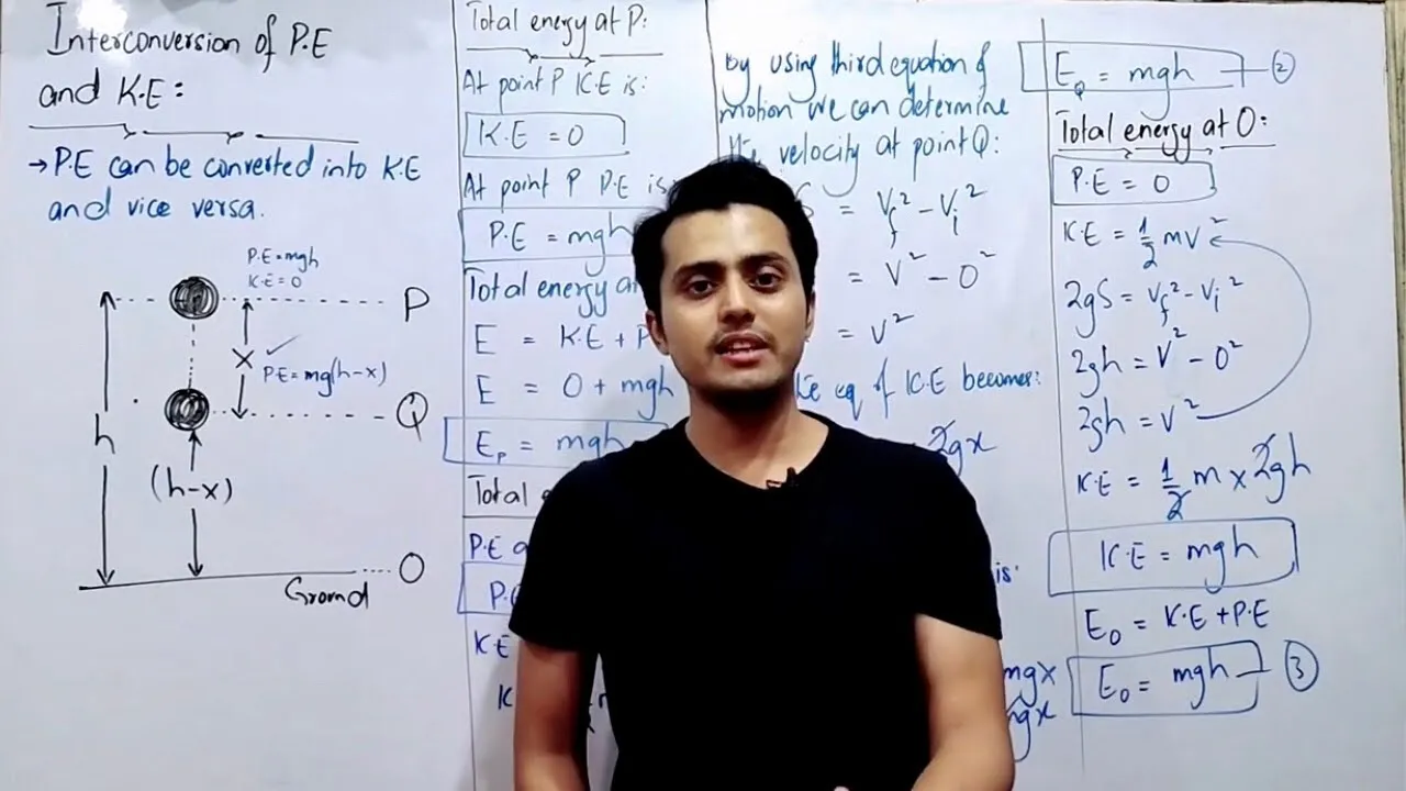
Interconversion of potential energy and kinetic energy || work energy equation || class 11
164.1K
The law of conservation of energy states that energy cannot be created or destroyed, only transformed from one form to another. In the context of potential and kinetic energy interconversion, this means that as an object falls, potential energy is converted into kinetic energy, but the total mechanical energy remains constant (assuming no non-conservative forces like friction are present). The total energy at any point equals the initial total energy.
Click to watch →

IGCSE EDEXCEL PHYSICS Energy Resources And Energy Transfers | Physics |Complete Revision Summary
2.9K
The Law of Conservation of Energy states that energy is neither created nor destroyed, but it changes from one form to another. In a pendulum, at the mean position it has maximum kinetic energy and no potential energy. As it swings to the extreme, it loses kinetic energy and gains potential energy. At the extreme position, it has maximum potential energy. When it swings back, potential energy converts back to kinetic energy. Similarly, in a roller coaster, potential energy converts to kinetic energy as it falls, resulting in maximum speed at the bottom.
Click to watch →

Numericals Physics | Chapter 6 | 9th Class Physics Numerical 6.4
29.6K
According to the law of conservation of energy, energy cannot be created or destroyed, only transformed from one form to another. In this context, kinetic energy converts to potential energy and vice versa during the stone's flight.
Click to watch →
Deep Dive
The basic mechanics of standard friction-based braking systems and how they dissipate kinetic energy as heat.

Braking System Fundamentals
145.9K
Braking converts kinetic energy to heat through friction between moving and stationary surfaces. Friction resists movement due to microscopic surface irregularities. Two types exist: static friction (non-moving surfaces, parking brakes) and kinetic friction (moving surfaces, standard brakes). Coefficient of friction measures resistance, varying by material and surface condition—for example, ice on concrete requires minimal force while rubber requires substantial force. Brake fade occurs when heat generation exceeds dissipation capability. Mechanical fade happens when drums expand away from linings during overheating, while lining fade occurs when friction material overheats and coefficient of friction drops.
Click to watch →

Mechanical Design (Machine Design) Clutches, Brakes and Flywheels Intro (S20 ME470 Class 15)
4.1K
Mechanical braking systems convert kinetic energy into heat through friction. Internal shoe drum brakes use pivoted shoes pressed against a rotating drum by hydraulic actuators. External shoe brakes and band brakes apply friction from outside the drum. Disc brakes, now standard in modern vehicles, use pads squeezed against a disc rotor. All systems share common requirements: appropriate friction materials that withstand high temperatures and pressures, effective actuating mechanisms, and predictable performance. Historical examples include muscle car drum brakes and contemporary disc brake systems.
Click to watch →
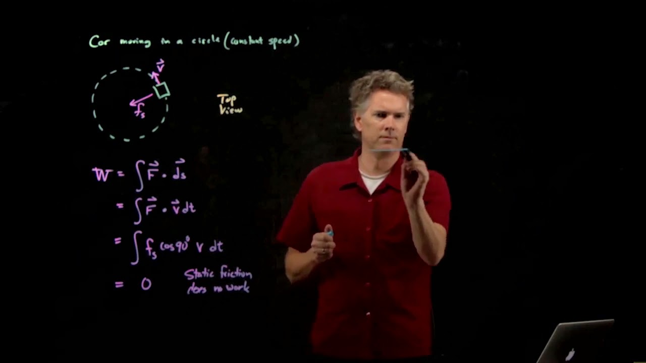
Friction and Cars | Physics with Professor Matt Anderson | M10-07
2.7K
When stopping a car, the brakes use kinetic friction to do the work that stops the car. The brake system consists of a metal rotor attached to the wheel and brake pads that press against the spinning rotor. As the rotor spins, the brake pads create kinetic friction that slows the car. This kinetic friction converts the car's kinetic energy into heat, which is why brakes get very hot during braking. This is fundamentally different from static friction, which does no work. The heat generated can be so intense that it can melt brake components, causing brake failure.
Click to watch →

Vehicle Dynamics & Control 14 - Powertrain 1: Engine and brake
8.8K
Friction brakes dissipate kinetic energy as heat through physical contact. Two main types exist: (1) Drum brakes: A rotating drum connected to the wheel has brake shoes with linings that press against the drum's inner surface when brakes are applied, creating friction; (2) Disc brakes: A rotating disc connected to the wheel has brake pads that clamp against both sides of the disc when brakes are applied. Both systems use hydraulic pressure to apply braking force, with return springs releasing the brakes. Brake fluid pressure is generated by the master cylinder when the brake pedal is pressed.
Click to watch →

Lecture - 39 Design of Breaks - I
73.2K
When brakes are applied, kinetic energy is converted to heat through friction. For translating masses, energy change is ΔKE = ½M(V₁² - V₂²). For descending masses, potential energy change ΔPE = mgH also occurs, where H = ½(V₁ + V₂)t. Rotating components contribute ΔKE_rot = ½I(ω₁² - ω₂²). Total energy dissipation equals braking torque times angular displacement: ΔE = T_brake × Δθ. With T_brake = RμF and Δθ = (ω₁ + ω₂)/2 × t, the required braking force is F = ΔE/(μR). Critical consideration is thermal stability of brake materials, as excessive heat can cause material degradation and failure.
Click to watch →
Deep Dive
Fundamental concepts of work, force, and mechanical advantage in simple mechanical systems.

BASİT MAKİNELER KONU ANLATIMI VE SORU ÇÖZÜMÜ |AYT FİZİK | 11.SINIF FİZİK| FİZİKLE BARIŞ
120.8K
Simple machines are mechanical systems without electronic complexity that provide work ease and time savings. They do not create energy or work but redistribute it. The fundamental principle is that work equals force multiplied by distance (W = F × d). When force is reduced, distance must increase proportionally to maintain the same work output. Force gain (KK) is calculated as the ratio of load to applied force (KK = P/F). If KK > 1, the system provides force advantage; if KK < 1, it provides distance advantage.
Click to watch →

MAQUINAS SIMPLES TRABAJANDO JUNTAS
241.2K
The four fundamental simple machines—inclined plane, pulley, wheel and axle, and lever—are the basic building blocks of mechanical devices. Work is defined as force multiplied by distance (W = F × d), and in simple machines, work input equals work output minus friction losses. Mechanical advantage is the factor by which a machine multiplies input force. Simple machines can be combined to create compound machines where mechanical advantages multiply. For example, pruning shears combine two levers (MA = 15 and MA = 3) for a total MA of 45. A car jack combines a wheel and axle (MA = 20) with a screw (MA = 15) for a total MA of 300. Cranes typically combine three or more stages, multiplying mechanical advantage further. This systematic approach allows machines to produce extremely large forces from relatively small inputs, making work easier through strategic force-distance trade-offs.
Click to watch →

ASVAB General Science Study Guide
121.6K
Simple machines transform force application to make work easier. Work equals force multiplied by distance (W = F × d). Input work equals output work (ignoring friction). Mechanical advantage (MA) is the ratio of output force to input force, or equivalently the ratio of input distance to output distance. MA > 1 means the machine amplifies force. Six types exist: lever (fulcrum-based), inclined plane (ramp), wedge (splitting tool), wheel and axle (rotating), pulley (rope and wheel system), and screw (inclined plane wrapped around cylinder).
Click to watch →

Basit Makineler Soru Çözümü | 42 günde AYT Fizik 18.gün
3.6K
Simple machines facilitate work by providing force advantage (less force required) or distance advantage (shorter distance traveled), but they cannot create additional work. The work principle states that work input equals work output minus losses. Lever-type machines are classified by fulcrum position: first-class (fulcrum in middle), second-class (load in middle), and third-class (force in middle). Pulley systems provide force advantage through multiple rope segments supporting the load. Inclined planes provide force advantage by distributing load over longer distance. Gear systems with concentric gears provide force advantage based on radius ratios. The fundamental trade-off between force and distance is consistent across all simple machines, demonstrating the conservation of energy principle.
Click to watch →

زانست | م.إدریس | وانەی دەیەم
164K
This comprehensive segment covers fundamental physics concepts including Newton's laws of motion, force measurement in Newtons (نيوتن), and work measurement in Joules (جول). The content explains how force causes objects to move or change their state of motion, and how work is calculated as force applied over a distance. The video introduces mechanical advantage and efficiency, explaining how machines can multiply force or change its direction. The segment explores various simple machines including levers, pulleys, and other mechanical devices that provide mechanical advantage in everyday applications. The content establishes foundational knowledge about physical quantities, their measurement units, and practical applications of physics principles in mechanical systems.
Click to watch →
Prerequisite Knowledge
- Concept 01Understanding Pascal's Principle and the basics of fluid mechanics, particularly how force and pressure are transmitted through confined liquids.
- Concept 02The Law of Conservation of Energy, specifically the conversion of kinetic energy into stored potential energy and back.
- Concept 03The basic mechanics of standard friction-based braking systems and how they dissipate kinetic energy as heat.
- Concept 04Fundamental concepts of work, force, and mechanical advantage in simple mechanical systems.
Subsequent Learning
- Step 01Exploring the design and mechanics of industrial hydraulic accumulators (such as gas-charged or bladder types) used to store high-pressure fluid.
- Step 02Comparing hydraulic regenerative braking with electromagnetic regenerative braking systems used in modern electric and hybrid vehicles.
- Step 03Investigating the real-world application of Hybrid Hydraulic Vehicles (HHVs) in heavy-duty machinery, delivery trucks, and public transit buses.
- Step 04Analyzing thermodynamic efficiency and energy loss factors, such as fluid friction and heat generation, within fluid power systems.
Opening
First Beat
Mid Point
Climax
Resolution
Finale
Opening
0:26Playing Section
- 1
Video begins with ambient audio and visual cues.
- 2
No spoken content is present in this section.
- 3
Sets initial tone for the upcoming narrative.
Electromagnetic Regenerative Braking: The Practical Alternative to Hydraulic Systems
While building a hydraulic regenerative braking model is an excellent physics demonstration, it represents a niche technology with significant real-world limitations. In the automotive industry, electromagnetic regenerative braking (using electric motors and batteries) is the dominant standard. Hydraulic systems require bulky high-pressure fluid accumulators, complex plumbing, and are prone to fluid leaks, making them impractical for passenger electric vehicles. In contrast, electromagnetic systems are lighter, highly scalable, and directly feed energy back into the vehicle's main battery. Introducing students to electromagnetic alternatives provides a more accurate representation of modern green transportation technology.
Deep Dive
Exploring the design and mechanics of industrial hydraulic accumulators (such as gas-charged or bladder types) used to store high-pressure fluid.

How hydraulic accumulators work
40.7K
Gas-charged accumulators consist of five key components: supply line (single connection to hydraulic circuit), poppet valve with spring, steel housing/shell, rubber bladder containing compressed gas, and gas supply valve for charging. These accumulators operate through three pressure-volume stages: pre-charge pressure (P0, V0) where gas fills the entire shell, maximum working pressure (P2, V2) with minimal gas volume due to compression, and minimum working pressure (P1, V1). Critical to proper operation is the pre-charge pressure requirement: it must be set between 70-90% of minimum working pressure to ensure hydraulic oil can enter and compress the gas during system startup.
Click to watch →

Gas Charged Accumulators Types
81.3K
Gas charged hydraulic accumulators store and release hydraulic energy based on Boyle's law, where gas pressure varies inversely with volume; they consist of a fluid section and gas section separated by an elastic barrier (bladder, diaphragm, or piston), with nitrogen under pressure acting as the spring to compress fluid during high-pressure conditions and release stored energy when system pressure drops.
Click to watch →

Gold Rush #scrap water pump sitting since 1966 Will it start? Hydraulic start?!
61.1K
A hydraulic accumulator contains a bladder or piston separating hydraulic fluid from pressurized nitrogen gas. As fluid is pumped in, it compresses the nitrogen, storing potential energy. A pressure gauge monitors pressure rise during charging. The system is designed to maintain charge during extended storage without losing pressure. The accumulator allows quick response when the starter is activated, enabling engine starting without continuous pumping.
Click to watch →

Hydraulics and Pneumatics Test #1 pptx
60.3K
Accumulators store pressurized fluid with a spring or gas charge to maintain system pressure and provide emergency power. Bladder type accumulators separate fluid from gas charge using flexible membranes. Weighted accumulators calculate pressure as weight divided by piston area (P=W/A). Nitrogen gas is preferred for gas charging due to its inert properties preventing fluid oxidation. Applications include leakage compensation in rotary chucks, maintaining pressure during pump downtime, and absorbing hydraulic shocks. Needle valves isolate accumulators for safety during maintenance.
Click to watch →

Stig Shift #23 (Aircraft Maintenance Adventures)
60.9K
Hydraulic accumulators store energy in a compressed gas bladder separated from hydraulic fluid by a metal body with an outer layer of Kevlar for strength. Each hydraulic system (green, yellow, blue) has one accumulator pre-charged to approximately 1,800 PSI. The accumulator maintains head pressure to reservoirs, keeps the system free from small pressure fluctuations, and provides a supply of fluid during temporary decreases in system pressure. This ensures continuous hydraulic function even if engine-driven pump response time is insufficient.
Click to watch →
Deep Dive
Comparing hydraulic regenerative braking with electromagnetic regenerative braking systems used in modern electric and hybrid vehicles.
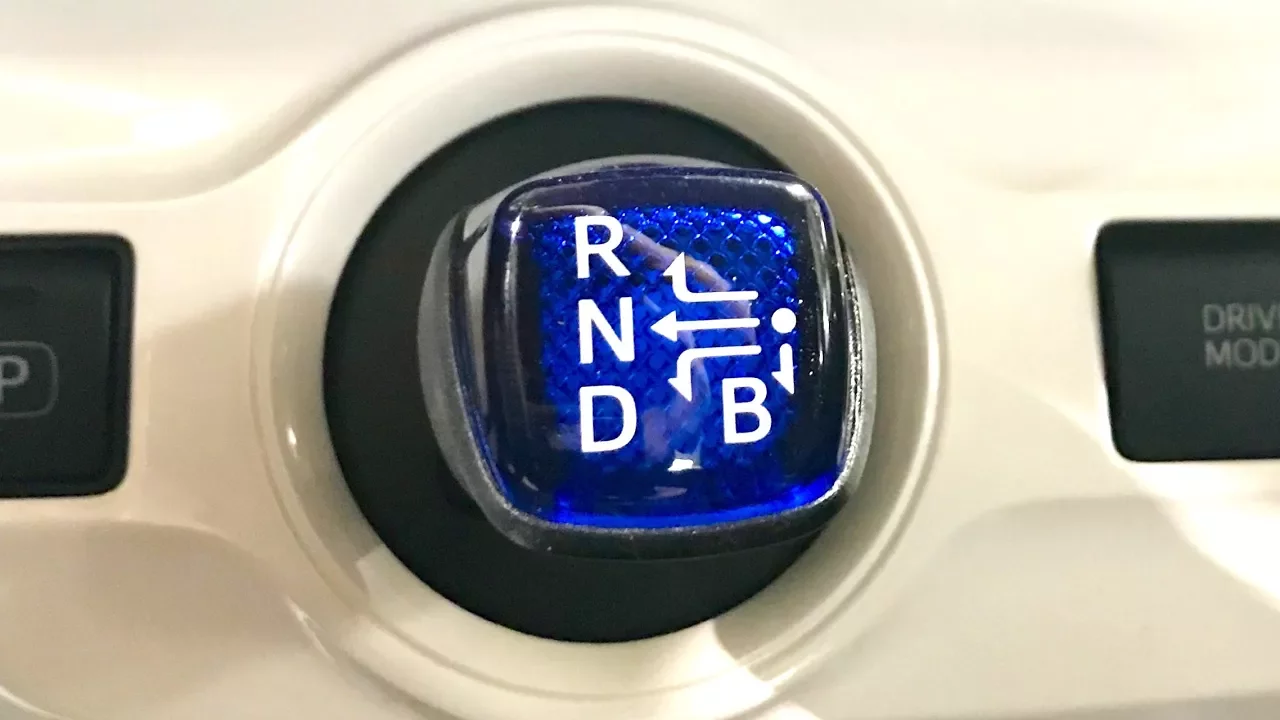
Hybrid and EV Regenerative Braking Systems
200.5K
Regenerative braking systems in hybrid and electric vehicles convert kinetic energy back to electrical energy during deceleration by using electromagnetic induction, where the rotation of permanent magnet rotors inside stator assemblies with three-phase windings induces alternating current; this induced voltage is then converted to DC and fed back into the high-voltage battery, with the inverter controlling the effective resistance to manage charge rate and braking force, while the opposing magnetic fields created by current in the stator windings provide the mechanical braking effect that slows the vehicle without relying primarily on hydraulic brakes.
Click to watch →

FRENOS REGENERATIVOS #frenos #automobile
82K
Regenerative braking is an energy recovery technology that converts kinetic energy from vehicle deceleration into electrical energy, which is then stored in batteries to extend vehicle range; unlike conventional friction brakes that dissipate energy as heat, regenerative brakes use an electric generator connected to the transmission to slow the vehicle while simultaneously charging the battery, though they require conventional hydraulic brakes for low-speed operation and emergency stops.
Click to watch →
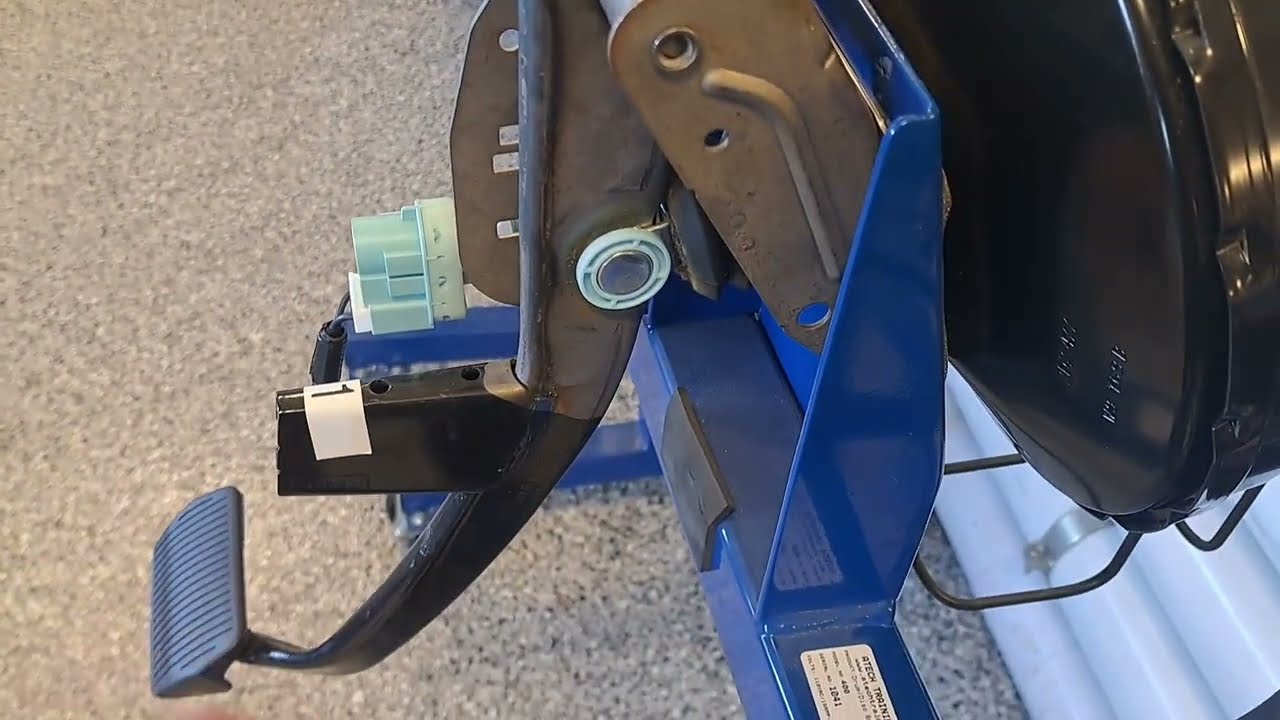
ASE A5 Brakes class brake boosters 101
5.5K
Electric over hydraulic brake boosters use an electric motor and computer to generate brake pressure. The ECU monitors pedal position and force, then controls a motor-driven pump to build brake pressure (typically 500 PSI). This system can provide variable assist and integrates with ABS and stability control. In hybrid vehicles, regenerative braking captures kinetic energy during braking by controlling the electric motor to slow the rotor, generating electricity that returns to the battery. The driver may feel minimal hydraulic pressure because regenerative braking handles most deceleration. Diagnosis involves checking for DTCs, verifying power and ground to the motor, and testing ECU communication on the vehicle network.
Click to watch →

Regenerative Braking - Explained
359.6K
Regenerative braking is a technology used in electric and hybrid vehicles that converts the kinetic energy of a moving vehicle into electrical energy during deceleration by using the motor as a generator; when the driver applies the brakes, the wheel rotation turns the motor, which induces an electrical current that travels through the controller to charge the battery, thereby improving fuel economy or extending electric vehicle range while simultaneously reducing brake wear since the motor assists in slowing the vehicle rather than relying solely on friction-based disc brakes.
Click to watch →

RIGENERATIVA o IDRAULICA? Distinguiamo la FRENATA con Hybrid Assistant!
884
Regenerative braking is a key feature of hybrid vehicles that converts kinetic energy back into electrical energy for storage in the battery. The system uses electric motors as generators, producing negative torque to slow the vehicle while recovering energy. The Hybrid Assistant display indicates braking type through color coding: green means regenerative braking is active, red means hydraulic brakes are engaged, and gray means no braking. This technology can reduce fuel consumption by 20-50% depending on engine specifications. The system automatically switches between braking methods based on driving conditions, vehicle speed, and road surface quality.
Click to watch →
Deep Dive
Investigating the real-world application of Hybrid Hydraulic Vehicles (HHVs) in heavy-duty machinery, delivery trucks, and public transit buses.

Hybrid cars are a combination of an electric car and a traditional gas-powered car.
130
Hybrid powertrains in heavy-duty applications use diesel-electric or turbo-electric configurations where engines drive generators powering electric motors or hydraulic systems. These systems excel in applications with frequent starts, stops, and idling—such as switching yard locomotives where engines idle 60-85% of the time. Retrofitting existing locomotives with hybrid systems achieves 40-80% fuel savings and pollution reduction. Rubber-tired gantry cranes recover lifting energy during container lowering, achieving 50-70% emission reductions. Commercial vehicles including delivery trucks, buses, and trucks benefit from hybrid systems, with retrofit kits paying for themselves through fuel savings. The distributed power approach through wires or pipes offers advantages over mechanical linkages, particularly for multi-wheel or multi-propeller drives.
Click to watch →

MAN TGM Hybride Hydraulique ! La bonne solution ?
8.1K
A hybrid hydraulic vehicle is a mechanical system designed for stop-and-go applications like garbage trucks. It captures kinetic energy during braking through a compressed gas pocket and releases it during acceleration, functioning as both an energy recovery system and a hydraulic retarder. The system is managed by an electronic control unit that modulates power delivery and can disconnect during safety system activation. Key benefits include at least 15% fuel economy improvement, reduced CO2 emissions, and decreased urban noise pollution. The 450 kg system weight is largely offset by reduced counterweight requirements in garbage trucks. This purely mechanical solution offers greater reliability and easier maintenance than electrical hybrid systems, with the added advantage that the energy recovery device can be removed for the vehicle's second life.
Click to watch →

Margo Oge, Office of Transportation and Air Quality, EPA - Washington D.C. Auto Show
486
Hydraulic hybrid vehicles use accumulators and hydraulic motors instead of batteries and electric motors, offering significantly lower costs (approximately one-third) while achieving substantial fuel economy improvements, particularly in stop-and-go urban driving where they can deliver up to 60% efficiency gains; this technology has proven most effective for heavy-duty applications like refuse trucks and delivery vehicles, with ongoing efforts to adapt it for lighter vehicles like minivans through continued engineering innovation and material improvements.
Click to watch →

The kids PICTURE SHOQ ROOFTILETKPS IS HYBRID VEHICLES I'M SAVE IT BEFORE IS BEING ERASE AWAY
8K
Hybrid vehicle technology has been applied across diverse transportation sectors including personal vehicles (SUVs, pickup trucks, vans), emergency services (fire engines, police cars, ambulances), commercial transportation (taxis, delivery trucks, city buses, tractor trailers), and rail transport (diesel electric locomotives). This demonstrates the versatility of hybrid power systems in reducing emissions and improving fuel efficiency across different vehicle types and operational contexts.
Click to watch →

How Hydraulic Hybrid System Work | Hybrid System for Truck
2.1K
Hydraulic hybrid technology represents an alternative to battery-electric systems for vehicles. It uses high-pressure cylinders with integrated motors that function as pumps to power the entire system. This technology offers significant advantages including fuel efficiency improvements of 50-100% and CO2 emission reductions of 60-70%. The system is particularly effective for commercial vehicles due to its ability to generate substantial power efficiently. Practical implementations, such as those used by UPS courier company, have demonstrated real-world benefits including reduced fuel consumption and lower emissions. The technology has been developed over centuries and continues to evolve, making it a viable option for improving commercial vehicle efficiency.
Click to watch →
Deep Dive
Analyzing thermodynamic efficiency and energy loss factors, such as fluid friction and heat generation, within fluid power systems.

Piping Systems 1
16.6K
This section extends Bernoulli's principles to practical engineering applications. Fluid power equals pressure change times volumetric flow rate, or energy per unit mass change times mass flow rate. Pump efficiency (η_pump = Ẇ_fluid/Ẇ_shaft) accounts for energy losses converting shaft power to fluid power. The modified Bernoulli equation incorporates pump head addition and frictional losses: H_pump = Δz + H_L + H_turbine. Major head loss in straight pipes uses the Darcy-Weisbach equation: H_L = f(L/D)(v²/2g). The friction factor depends on Reynolds number (Re = ρVD/μ) and relative roughness (ε/D), with laminar flow using f = 64/Re and turbulent flow requiring the Moody chart or Churchill correlation.
Click to watch →

Fluid Mechanics N5: HYDRODYNAMICS (Chapter 6) - Introduction to Bernoulli's Equation
3.2K
When energy leaves a fluid system, the equation becomes: energy before = energy after + energy loss. Friction causes energy loss during pipe flow as particles rub against surfaces; loss magnitude depends on velocity and surface roughness. Frictional energy loss per unit weight is denoted h_f. Mechanical efficiency measures useful output versus input energy, calculated as energy after divided by energy before, or (H - h_f)/H. This accounts for real-world fluid system performance where idealized assumptions don't hold.
Click to watch →

شرح قاعدة باسكال/ تطبيقات الضغط عند نقطة فى باطن سائل/ فيزياء ٢ث ٢٠٢٥م/ الترم الثانى
1.1K
Hydraulic system efficiency is the ratio of output work to input work, or output force to input force, or output area to input area. Efficiency is always less than 100% due to energy losses from friction between fluid molecules and between fluid and container walls. The efficiency formula can be expressed as η = F_large/F_small = A_large/A_small = W_large/W_small.
Click to watch →

TK2107 Mekflu 09 Friksi_Fitting
1.5K
This section covers the energy losses due to friction in fluid flow. Energy loss manifests as heat (panas friksi) and is calculated as the product of friction force and distance traveled (E = F × ΔX). The rate of friction heat generation is obtained by dividing by time, giving units of joules per second. Specific friction heat normalizes this energy loss per unit mass of fluid, calculated as (F × ΔX) / m, with units of joules per kilogram. This parameter is essential for comparing energy losses across different flow conditions and pipe sizes.
Click to watch →

Fluid Mechanics: Chapter3 (Conservation of Energy) Review
5.7K
Power in fluid systems is calculated as the product of weight flow rate (γQ) and head (H). The instructor explains that power represents the rate of energy transfer in the system. Efficiency (η) represents the ratio of useful energy output to total energy input, and is always less than 1 due to energy losses from friction, heat transfer, and other factors. For pumps, P_out = η × P_in, while for turbines, P_out = η × P_in. Friction head loss is calculated using empirical formulas like the Darcy-Weisbach equation, accounting for pipe roughness, flow velocity, and pipe dimensions. Understanding these relationships is essential for analyzing pump and turbine performance and designing efficient fluid systems.
Click to watch →
Opening
First Beat
Mid Point
Climax
Resolution
Finale
Opening
0:26- 1
Video begins with ambient audio and visual cues.
- 2
No spoken content is present in this section.
- 3
Sets initial tone for the upcoming narrative.
Electromagnetic Regenerative Braking: The Practical Alternative to Hydraulic Systems
While building a hydraulic regenerative braking model is an excellent physics demonstration, it represents a niche technology with significant real-world limitations. In the automotive industry, electromagnetic regenerative braking (using electric motors and batteries) is the dominant standard. Hydraulic systems require bulky high-pressure fluid accumulators, complex plumbing, and are prone to fluid leaks, making them impractical for passenger electric vehicles. In contrast, electromagnetic systems are lighter, highly scalable, and directly feed energy back into the vehicle's main battery. Introducing students to electromagnetic alternatives provides a more accurate representation of modern green transportation technology.
Understanding Pascal's Principle and the basics of fluid mechanics, particularly how force and pressure are transmitted through confined liquids.
The Law of Conservation of Energy, specifically the conversion of kinetic energy into stored potential energy and back.
The basic mechanics of standard friction-based braking systems and how they dissipate kinetic energy as heat.
Fundamental concepts of work, force, and mechanical advantage in simple mechanical systems.
Exploring the design and mechanics of industrial hydraulic accumulators (such as gas-charged or bladder types) used to store high-pressure fluid.
Comparing hydraulic regenerative braking with electromagnetic regenerative braking systems used in modern electric and hybrid vehicles.
Investigating the real-world application of Hybrid Hydraulic Vehicles (HHVs) in heavy-duty machinery, delivery trucks, and public transit buses.
Analyzing thermodynamic efficiency and energy loss factors, such as fluid friction and heat generation, within fluid power systems.
18.3K views286likes6:11@InventorChannel2025Original Release: 2024-07-30
[Music] [Music] oh a [Music] oh [Music] [Music] a [Music] oh oh [Music] [Music] [Music] he [Music] [Music]
Up Next

6:27
Supercapacitor Bank 2.7V 500F: Real Capacity Testing & Applications
@MousaSimpleProjects
200.9K views•2019-02-24

30:32
Ultrasonic Transducers: Resonant Frequency Measurement and Horn Design
@imajeenyus42
229.9K views•2017-02-22

54:16
Polymer Environmental Degradation: Mechanisms & Stabilization
@iit
1.8K views•2012-07-10

33:39
How a Student's Question Saved a NYC Skyscraper from Collapse
@veritasium
22.8M views•2025-04-26
Related Study Plans & Knowledge Roadmaps
Structured learning paths in Engineering
engineering
Building Acoustic Levitators: Physics & Arduino
01The Physics of Sound and Standing Waves
02Piezoelectric Transducers and H-Bridge Drivers
03Arduino Programming: Generating 40 kHz Signals
+ 2 more learning modules
14h5 modules
Explore Roadmap
engineering
Building Peltier Cloud Chambers: Particle Tracks
01Cosmic Rays & Cloud Chamber Physics
02Thermoelectric Cooling (TEC) Fundamentals
03Custom Liquid-Cooling Loop Design
+ 2 more learning modules
18h5 modules
Explore Roadmap
engineering
Yagi-Uda Antennas: Modeling, Build & VNA Test
01Introduction to RF and Antenna Fundamentals
02Yagi-Uda Antenna Design Principles
03Antenna Modeling and Simulation in 4NEC2
+ 2 more learning modules
18h5 modules
Explore Roadmap
engineering
ECG Monitor Design: Op-Amps, Filters & Noise
01Electronics & Breadboard Basics
02Op-Amps and Instrumentation Amplifiers
03Bioelectricity and ECG Fundamentals
+ 2 more learning modules
18h5 modules
Explore Roadmap