























The HMC5883L is a 3-axis magnetometer sensor that measures Earth's magnetic field to determine heading direction, interfaced with Arduino via I2C communication using only two wires (SCL and SDA); the sensor outputs raw X, Y, and Z axis values which are scaled and processed to calculate compass heading in degrees, with applications including robot navigation and directional control systems.
Arduino Compass with HMC5883L Magnetometer: I2C Interface and Programming Tutorial
Added:Basic Arduino programming, including writing sketches, utilizing the Arduino IDE, and using the Serial Monitor for debugging.
Fundamental concepts of the I2C (Inter-Integrated Circuit) communication protocol, specifically SDA and SCL lines and device addressing.
Basic trigonometry, specifically how to use the tangent/arctangent (atan2) function to calculate angles from 2D vector coordinates.
Elementary physics of magnetism, including the concept of Earth's magnetic field and how magnetic sensors measure magnetic flux density in Gauss or Microteslas.
Magnetometer calibration techniques, specifically addressing hard-iron and soft-iron distortions to eliminate local magnetic interference.
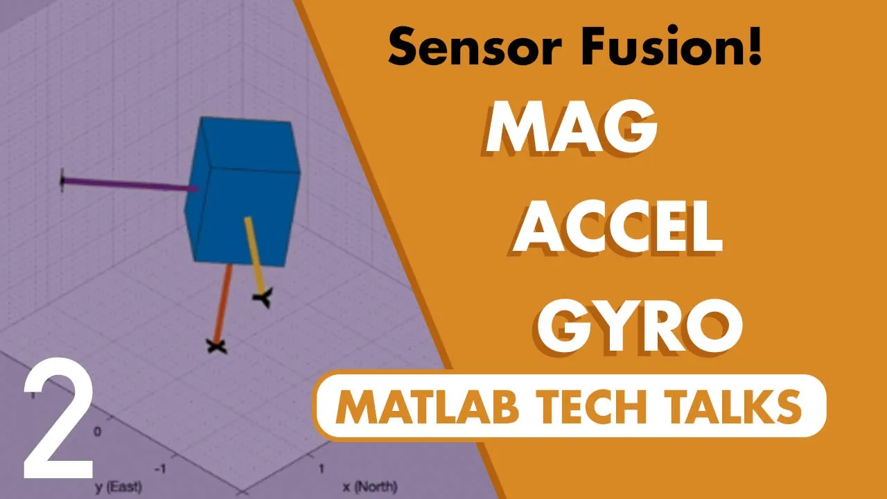
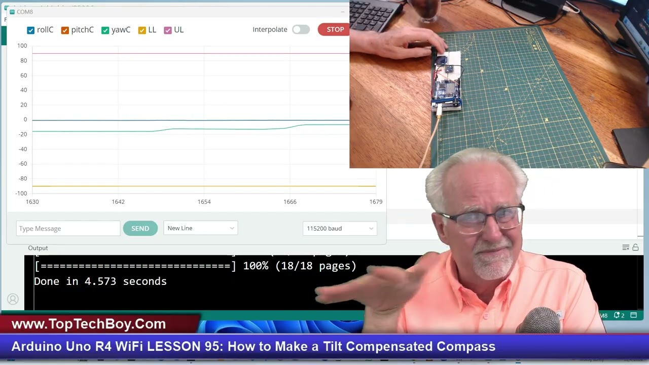
Tilt compensation implementation, which integrates an accelerometer to maintain accurate heading calculations when the sensor is not perfectly level.
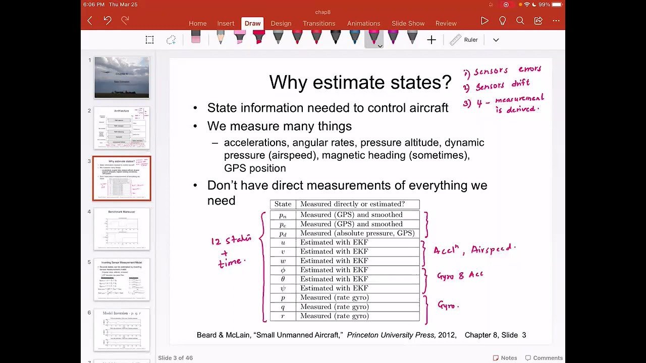
Sensor Fusion algorithms, such as Kalman Filters or Complementary Filters, to combine magnetometer data with gyroscopes and accelerometers (IMUs).
Application of heading data in autonomous navigation projects, such as GPS-guided rovers, marine autopilots, or unmanned aerial vehicles (UAVs).
31.7K views271likes11:25Original Release: 2018-11-16
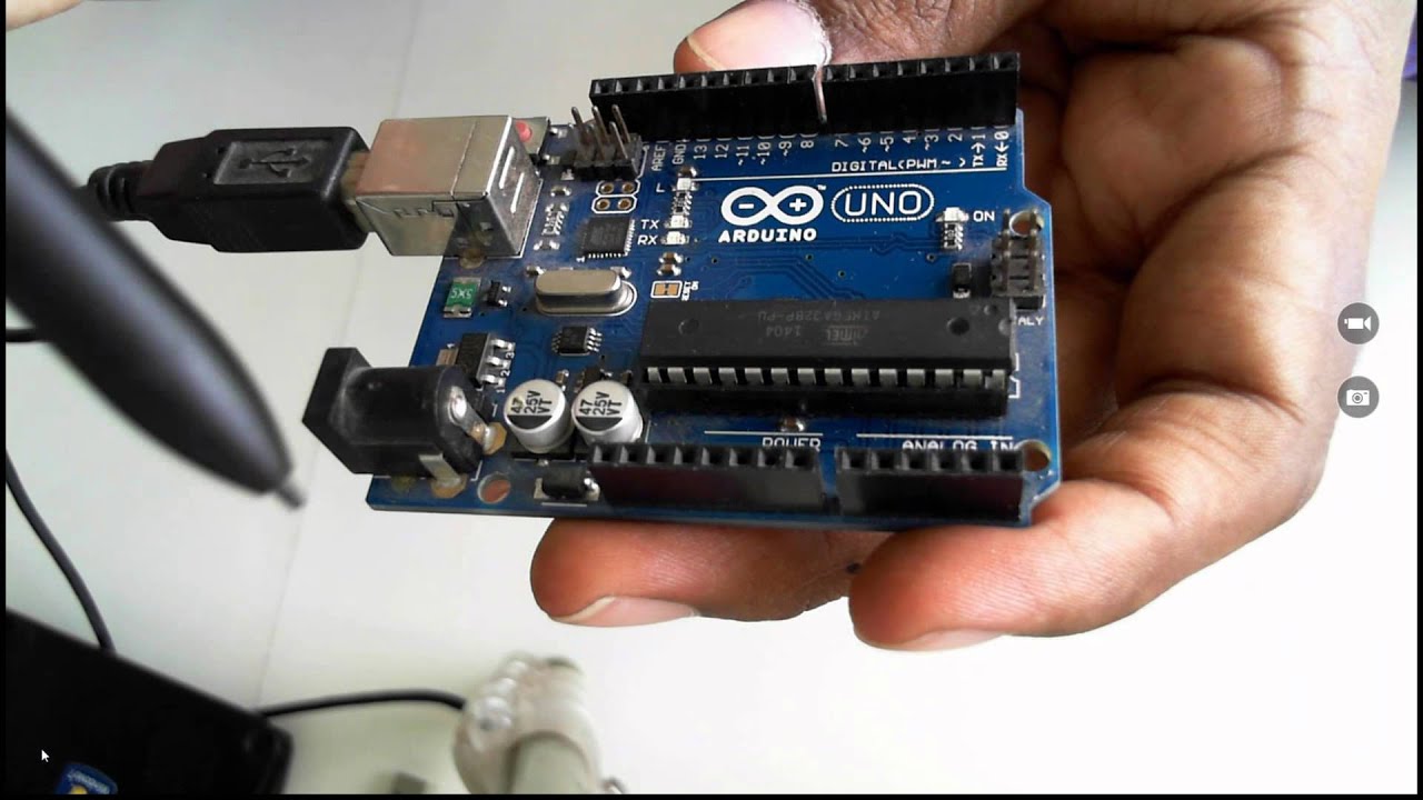
today's episode is about the H mc5 a double eight three-year magnetometer 3xs sensor this is most commonly used in robotics for the navigation purposes using this sensor you can easily find the direction this episode covers these circuit connections programming and testing let's get started this is the h MC v double h 3l magnetometer 3xs sensor as you can see my friends the pins are labeled with VCC ground SEL SDA and drdy if you look at the h MC 5 double 8 3 l features you will come to know that the h MC 5 double atrial can be connected to the arduino using i2c communication bus now the question is what is I 2 C bus i - c communication bus has become very popular and now commonly used by thousands of electronic devices because of its easy implementation by the easy implementation i mean that you can connect such devices as hm c 5 double 8 3 l which supports i - c bus can be connected using only two wires using only two wires we can connect many devices is every device has its own unique address so no reference this is the connection diagram of the hm c 5 w 8 3 l which is really easy as this is using the i2c communication and will be using only two words - which are the SCL and SDA so starting with a VC C we can connect the VCC of the hm c 5 double 8 3 l with 3.3 volt and all three to 5 volt but I recommend that you should connect this sensor with the 5 fault of the Arduino and then there is ground the ground oh da h MC 5 double 8 3 l should be connected with the ground and the SEO should be connected with halo 5 and the is ETA should be connected with a 4 and the drdy is not connected so this is really very basic circuit diagram and this is really easy and we will also be using an ad which is on page 13 of the arduino so we will make a decision on a particular angle and then we will turn on and turn off that led so now let's connect the H mc5 w3l with the arduino udo and after interfacing hm c v w3 l with Orban on you will start the programming and then finally the testing so let's get started so our friends for the interfacing you will be needing for jumper where is male to female type connect the red wire with the VCC gray wire with the ground orange wire with SEL and last wire with the SDA sum of friends as you can see the red wire is connected with the 5 fold and the gray wire is connected with the ground and the SEL is connected with a 5 and the SG is connected with a 4 so now let's connect or you know with the laptop and then we will start the programming so reference as you can see the Arduino is connected with a laptop it's on so start with the reference the i2c library which is hash include' wired art H and reference the H mc5 double h 3l campus library hash include' hm c 5 ee r 3 l dot h so make sure that you add these header files otherwise it won't work so the haitian cool means that it's a preprocessor directive and you have to add these two libraries store over campus as a variable - hm c 5 w 3l compass and then a terminator which is a semicolon and record any error that may occur in the compass or integer error equals to zero integer LD pin equal stress routine so at the beginning I told you that we will be controlling an LD depending on the angle okay so for that we are we will be using the Arduino booty which is on pin number 13 of the Arduino so out setup protein here we will configure the microcontroller and the company my friends that every mega and our DNA you know program has at least two functions which are the way it should have been the way it flew so we start with the white set of white means that this function is not returning any value and the empty parenthesis means that this function is not taking any or our argument as the inputs are same for the white loop and so initialize the serial port so as we will be sending the angle data to the serial monitor so for that we will have to activate the serial communication so we were using serial dot begin 9600 so as you can see this is also a function but it's taking the the baud rate is the input and this bothered you can change if you want so this is 96 so currently this is 9600 which is bits per second pen mode LD pin output so as you notice that the LD is an output device so that's why it's out for serial dot print line starting the eye you see in interface and wired art began so she'll dot print line encompass equals to this and pseudo dot print line error is equal to comp a start scale 1.3 so set the scale of the compass if error not equal to 0 if there is an error printed out 0 dot print line compass target error text error sealed our trend line setting measurement mode to continuous and error equals to compass dot set measurement mod measurement underscore continuous said the measurement mode to continuous and if error not equals to 0 if there is an error print at our serial dot print line compass target error text error you can download this quote from my blogger page I will give going in the description and now we start with a wide loop so Magneto meter raw this is the raw data or I equal two composite art read the raw access so retrieve the scaled values from the compost scale to the confit scale so magnetometer skilled skilled equal to compass storage skills access values are exist like so that you scaled our x-axis or y-axis our z-axis calculate heading when the magnetometer is level then correct for signs of the axis so when we use this instruction and once you have your heading you must then add your declination angle which is the error of the magnetic field and your location so you can find this from this website so floor declination angle equals two point zero four five seven heading plus equals declination angle and correct for wind signs are reversed so if heading is less than zero heading plus equals to 2 into PI and check for robbed due to addition of declination so f heading greater than two enterprise the heading minus equals to 2 into PI convert radians to degrees for liabilities of float heading degrees equals two heading into 180 divided by him underscore PI output the data where the serial ports or output raw scaled heading and heading degrees so these are all the wheels which we will sending to the 0 monitor so normally we will delay the application by 66 milli seconds to allow the loop to run 8 15 Hertz default bandwidth for the HMC 5-tuple 8 3 l however since we have a long serial out 1 0 4 ms 8 9600 we will let it run at its natural speed delay 66 milliseconds okay so now out the data down the serial ports a wide output magnetometer ah and the magnetometer scaled and we've scaled float heading and float so actually this is you can see it's a function with a named output and it's taking 1 2 3 and 4 inputs as the arguments and you can see it's type is white it means that this function is not returning anywhere you so serial to our printer rod then we use a tape and seed allotment raw dot access serial dot print then there's nothing empty and seeded or intro dot y X's and then Z X's so I'm pretty much the same and so then we're here we are using a condition that if the heading degree is greater than or equal to 1 and heading degrees less than equals to 45 then what to do then turn on the ill G which is on pin number 13 and if any other angle then keep it to low so that's the program you can download this program from my blogger page I will provide a link in description and now let's upload this code so now the the program is uploaded and now let's on the serial monitor so my friends over here you can see the degrees are currently it's a four point three to four point something like in degrees and we're here on the screen you can also see that the LED is on so if I turn it on you can see the angle the angle is also changing no the angle is 15 and it's not increasing like so it's 39 40 41 and now you can see the AOD is turned off is the current the angle is greater than 45 so the the LD which is on pin number 13 is off so as you can see no it's again it's turned on because the angle is below 45 so this way you can restrict the movement of a robot or any other part of a machine so that it always stays at state angle so now you can actually modify this code you can use the F else conditions and you can control motors with it you can now send these values to the LCD so there is no need to send all these values you have to you have to send only this value which is which is the heading degrees you have to call this and you have to send only these values to the LCD or to a computer application or you can also wirelessly send this data to another location so I hope you like this episode you like my video share my videos with your friends see you in next episode and thanks for watching
Up Next

6:00
Waterproofing RC Electronics at Home: A Hands-On Test of CorrosionX
@IRONCLADRC
7.6K views•2022-07-26

26:22
Walking in the City: Urban Rituals and the Flâneur in Contemporary India
@PSBTIndia
1.9K views•2016-08-02
9:35
HX711 Load Cell Calibration with Arduino for Accurate Weight Measurement
@ElectroniClinic
22.7K views•2018-10-12

1:42
Game of Thrones Opening Credits: A Cinematic Analysis
@gameofthrones
46.3M views•2011-04-18
Related Study Plans & Knowledge Roadmaps
Structured learning paths in General & Interdisciplinary Studies
general-studies
Artificial Light: History, Tech & Human Impact
01The Pre-Electric Era: Fire, Oil, and Gas Lighting
02The Incandescent Revolution and Grid Electrification
03Gas Discharge and Fluorescent Illumination
+ 3 more learning modules
14h6 modules
Explore Roadmap
general-studies
Elevator Engineering: History, Physics & Cities
01From Hoists to Safety Brakes: The Dawn of Vertical Lift
02Hydraulic vs. Traction: The Engineering Physics of Elevators
03Modern Speed, Safety, and Algorithms
+ 2 more learning modules
12h5 modules
Explore Roadmap
general-studies
Rubber: Material Science, History & Geopolitics
01Origins of Natural Rubber & Mesoamerican History
02The Chemistry of Natural Rubber & Vulcanization
03The Geopolitics of the Rubber Boom & Colonization
+ 2 more learning modules
12h5 modules
Explore Roadmap
general-studies
Containerization: Evolution, Logistics & Trade
01Ancient Trade & Bulk Cargo: Amphorae to Barrels
02The Industrial Revolution & Cardboard Packaging
03The Containerization Revolution: Malcom McLean
+ 2 more learning modules
12h5 modules
Explore Roadmap