


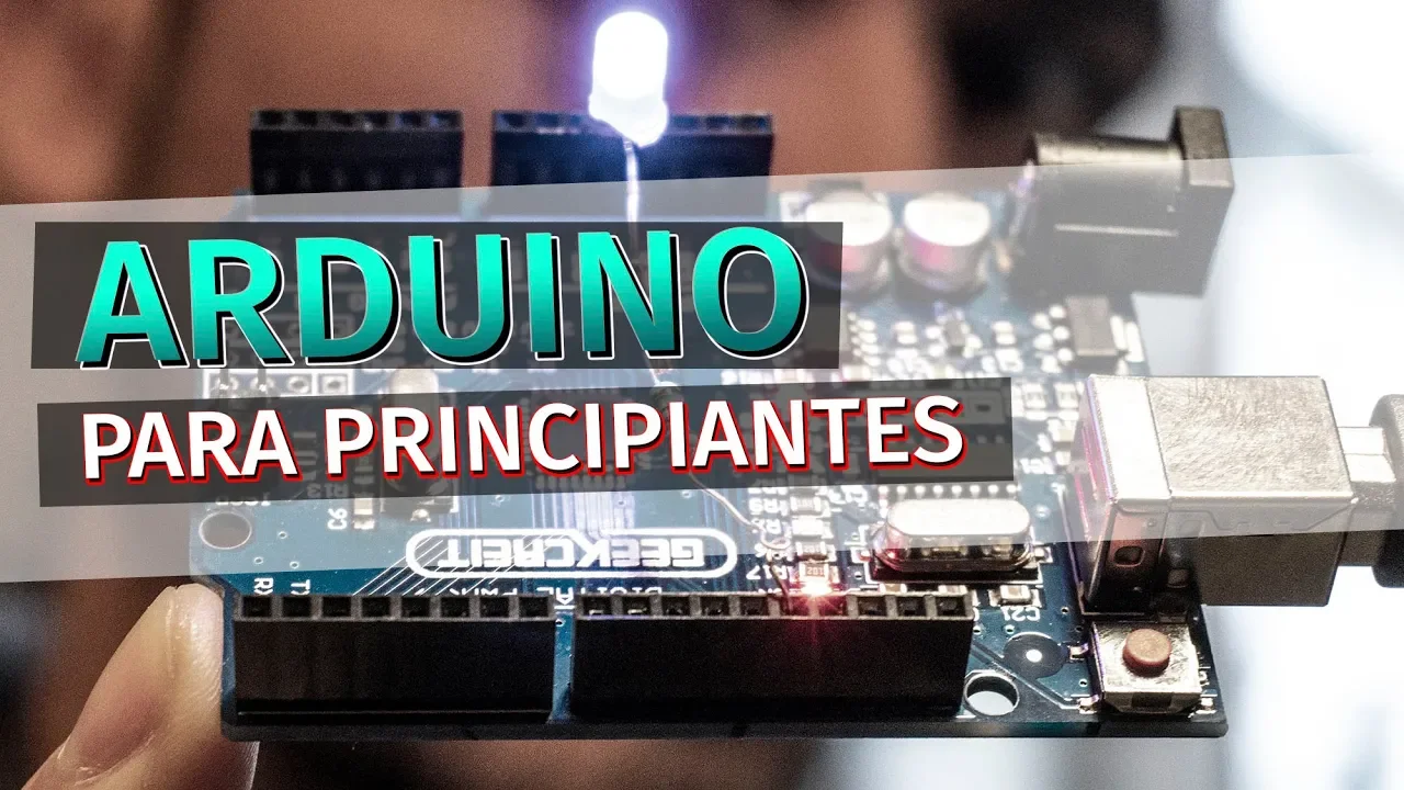


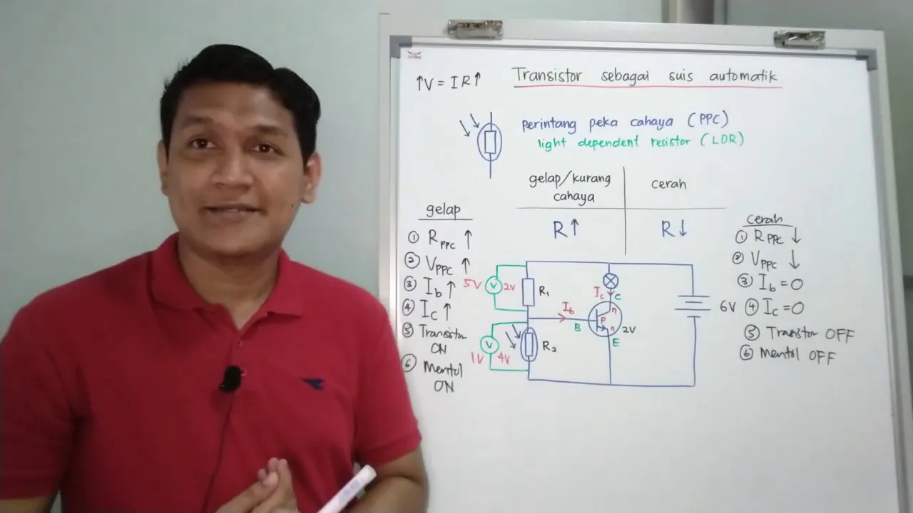
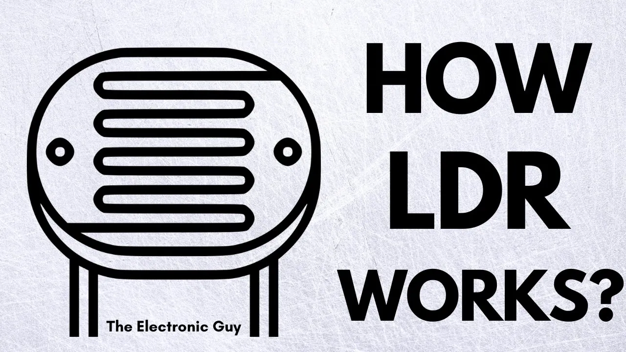
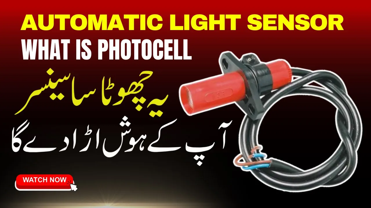
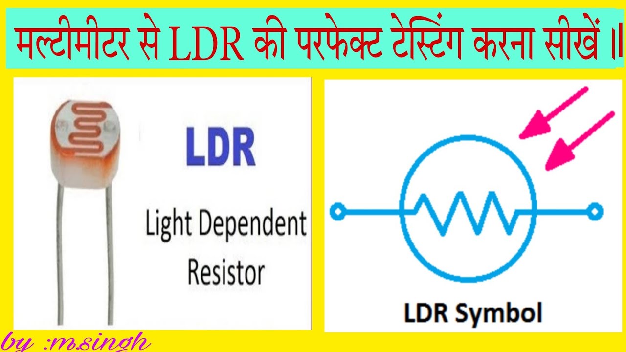




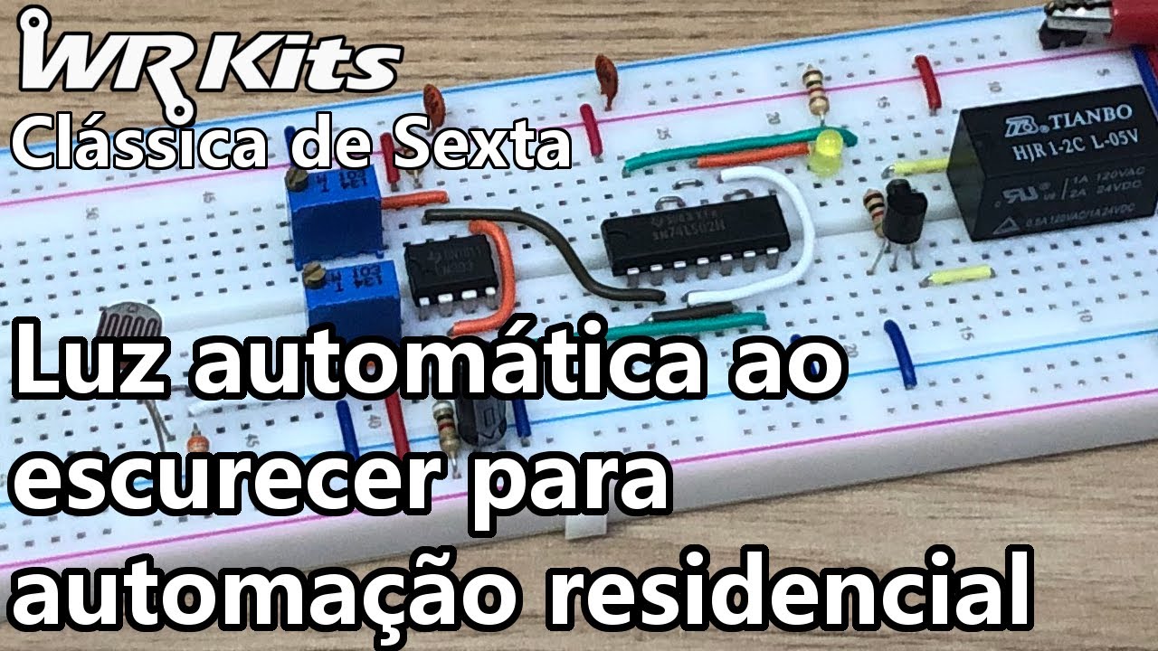




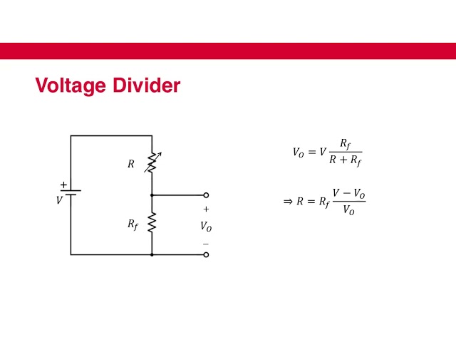


A Light Dependent Resistor (LDR) is a sensor whose resistance decreases as light intensity increases, and when connected in a voltage divider circuit with a 10kΩ resistor to an Arduino's analog input pin (A0), it can detect ambient light levels; the Arduino reads this analog value and can trigger an LED output (connected to a digital pin with a 220Ω current-limiting resistor) to turn on when the LDR detects darkness, enabling automatic light-activated projects.
Arduino LDR Voltage Divider for Light Sensing: LED Control Tutorial
Added:Basic understanding of Ohm's Law (V=IR) and how resistors restrict current flow in a circuit.
Familiarity with the Arduino platform, including the pin layout (analog vs. digital pins) and how to upload basic code using the Arduino IDE.
The fundamental working principle of a Light Dependent Resistor (LDR) and how its resistance changes in response to light.
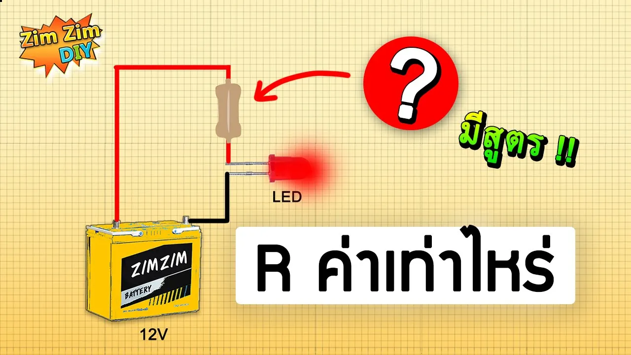
Basic breadboarding and prototyping skills, including how to wire an LED with its required current-limiting resistor.
Implementing software hysteresis (thresholding) to prevent LED flickering when light levels hover right at the trigger boundary.
Using Pulse Width Modulation (PWM) to dynamically dim or brighten the LED based on ambient light levels, rather than simple binary control.
Developing self-calibration algorithms in code to automatically adapt the sensor's threshold to different environmental conditions on startup.
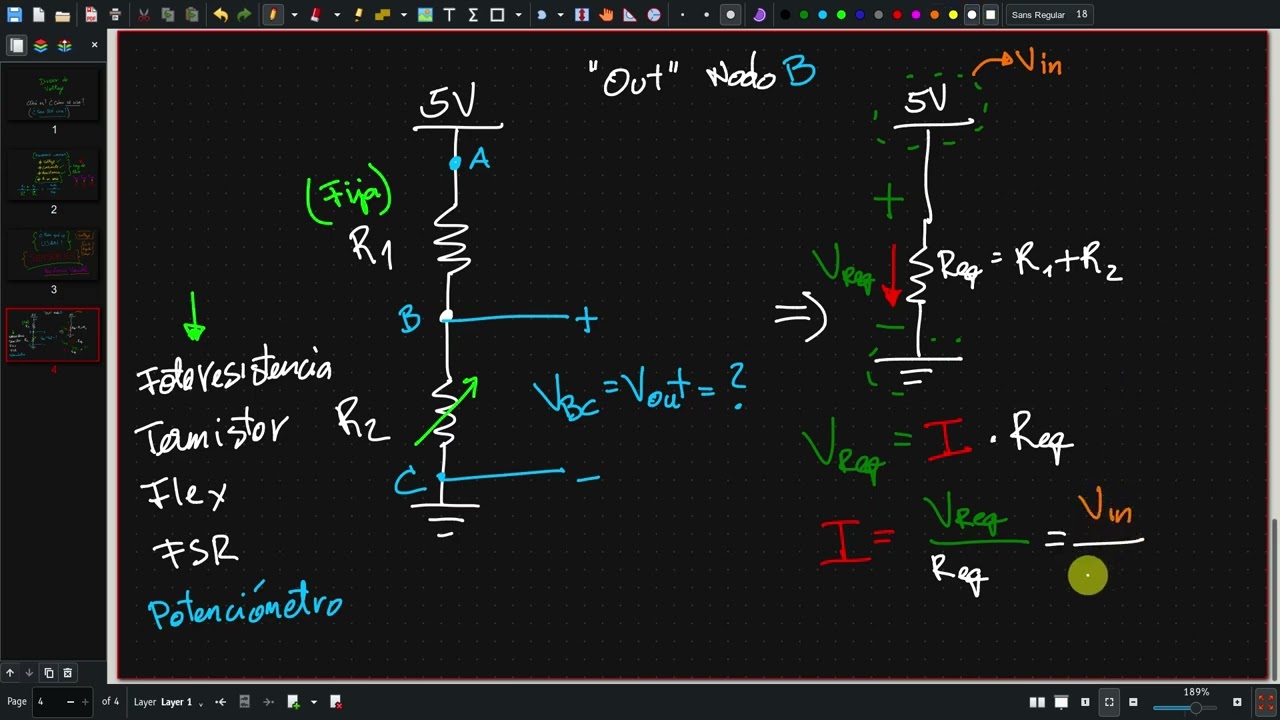
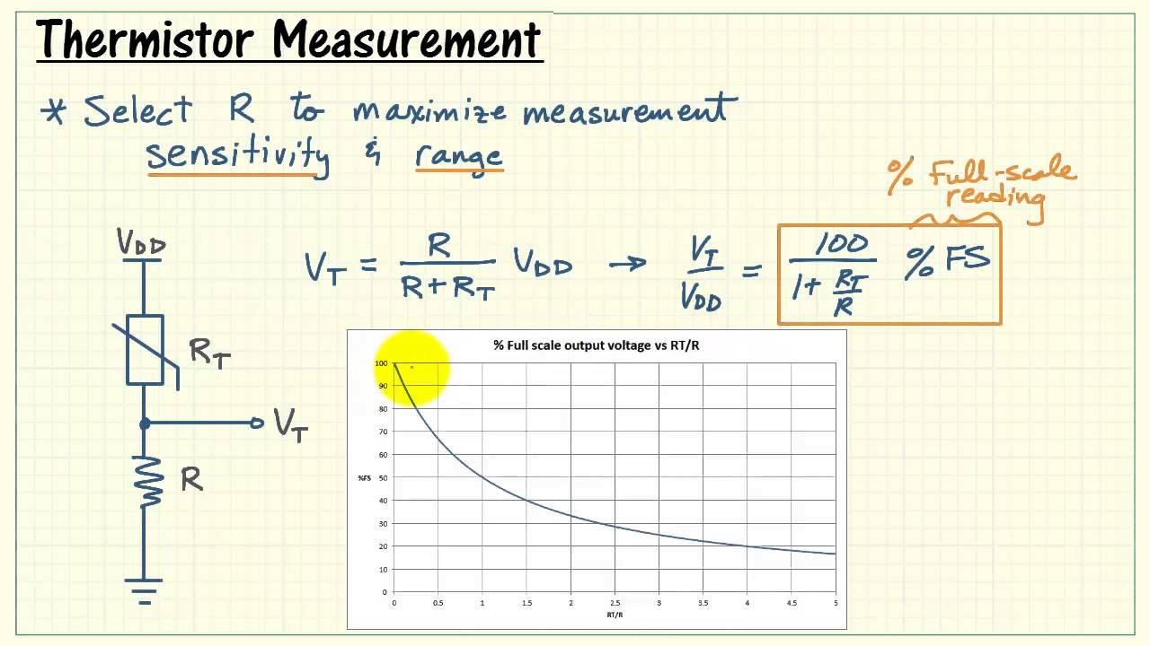
Applying the voltage divider principle to other resistive analog sensors, such as thermistors (for temperature) or flex sensors.
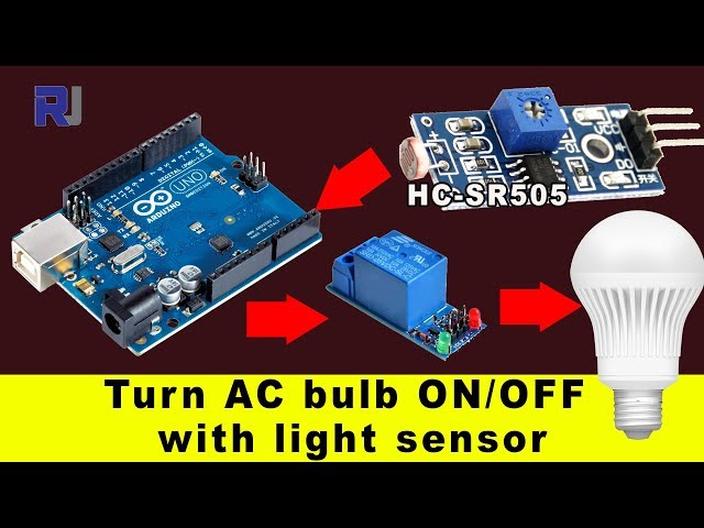
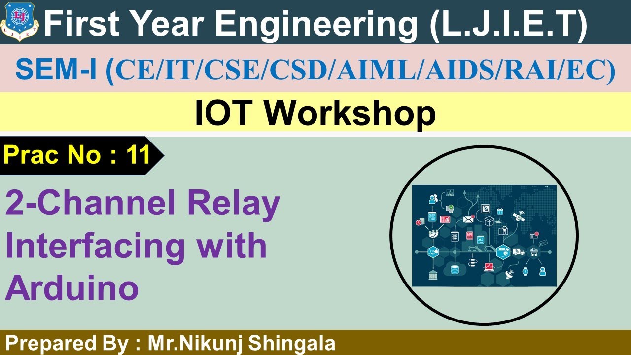
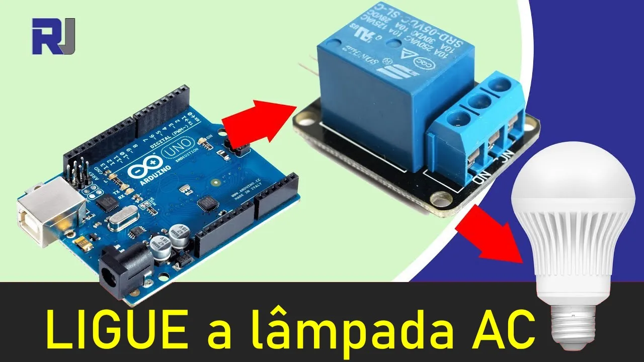
Interfacing the Arduino with a relay module to control actual AC household light bulbs, paving the way for home automation projects.
170 views7likes9:01Original Release: 2023-04-28
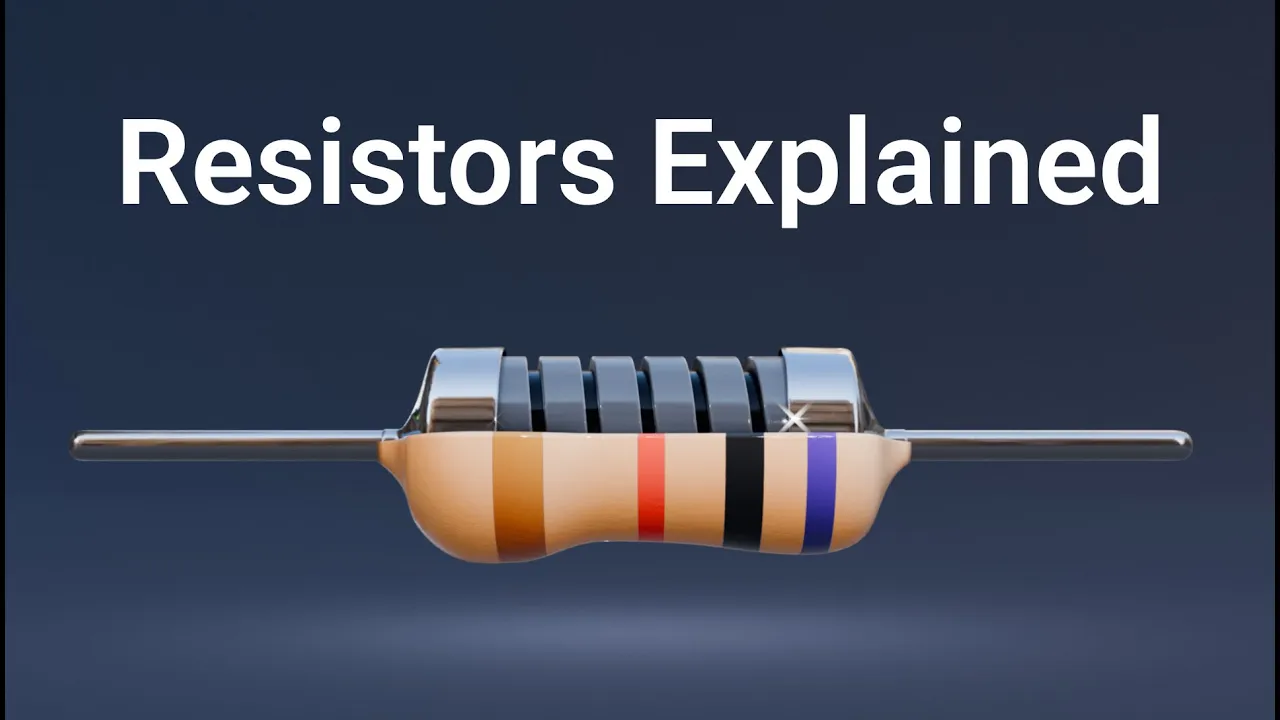
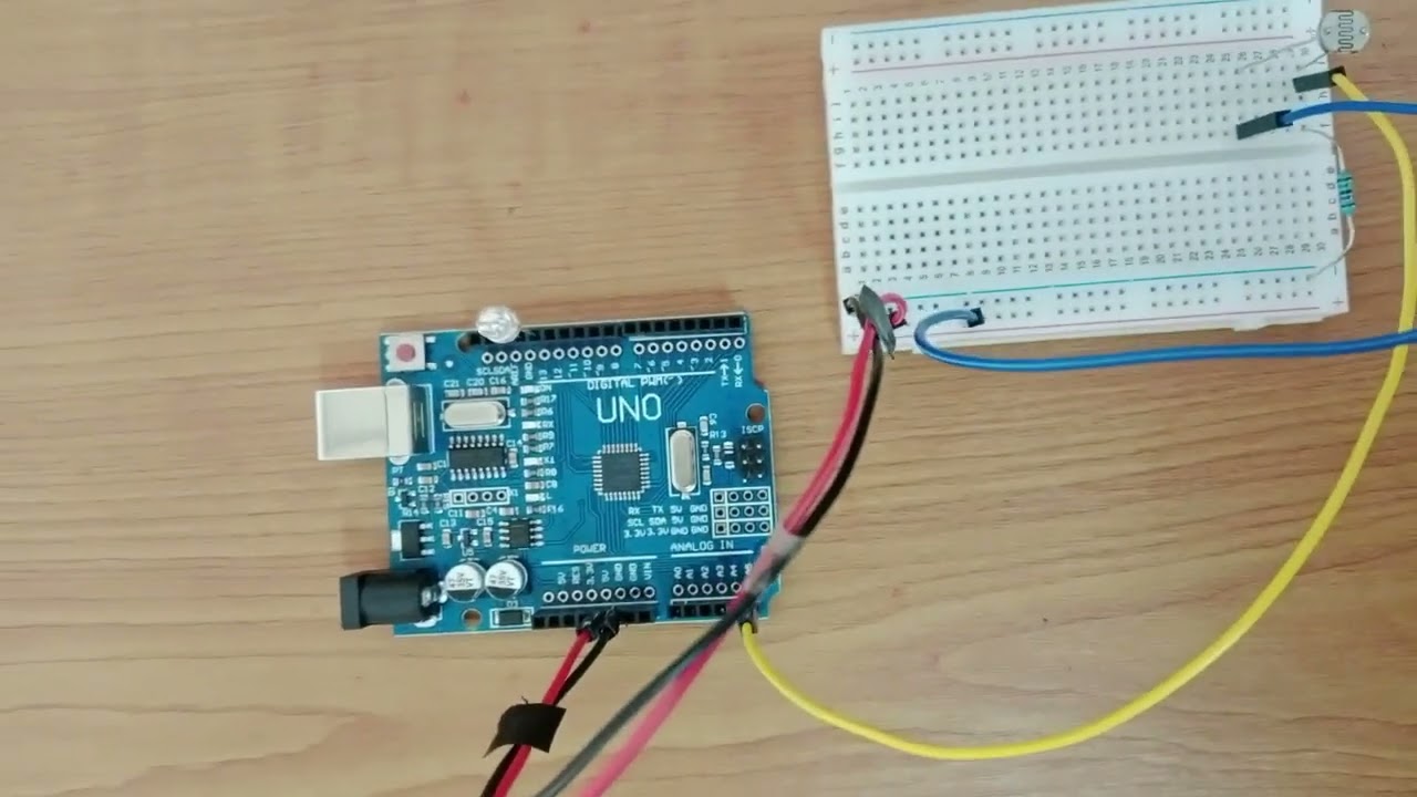
foreign [Music] for today I'm going to show you how to use the ldr or light detector restore with with an LED output so let's start by uh mounting the ldr to our breadboard we will connect the ldr and uh 10 kilo ohms resistor in series uh constituting a voltage divider circuit okay and with some connectors we will connect the other side of the resistor to our ground and then we will connect the other side of the ldr to our positive 5 volts in addition we will connect a connector between the ldr and the RC store that will serve as a signal power for our Arduino board so don't forget to wear up the five bolts of our Arduino into our breadboard and also connect a ground from our Arduino to our breadboard let's put some LEDs to our breadboard as an output let's switch so let's connect the negative side of the LED to our red bird if I notice that the shorter pin is the negative side of our LED so we will put it this way the shorter pin of our LED is connected to the ground pin of our breadboard and if you're using LEDs with Arduino don't forget to add 220 ohm surface store to prevent the LED to get busted so let's connect resistor in series on our lid so and then connect some connector from the end of the resistor to our Arduino okay let's connect here then we will be using pin 2.
on our Arduino board okay so this circuit is uh if the ldr detects snow light uh we will going to Output high or we will light up our LED every time we he covered the ldr not detecting any light so if the ldr detects like the LED is of X and when the ldr receives no light while we cover it the LED lights up so our signal pin of our ldr we were going to use pin a0 of our Arduino board as analog input so that's it RC our circuit is complete so for the code please check the description for the code of this circuit so let's try to upload the code as you open the code you can see that we have our LED connected at Pin 2 and our ldr signal connected at Pin a0 so we set our LED as a digital output and well in the loop uh uh every 500 milliseconds we read the signal from our ldr so let's upload the code to see the behavior of our ldr so this project you can use these uh the automate automatic light when it gets dark and many more oh so once you uploaded the code let's open up our serial monitor displayed here is the signal reading of our ldr so when we cover up the ldr you can see that that our LED lights up and uh signal reading of our ldr drops to around 200 so depending up on your application you can change this value so if you want to uh power on something uh before it gets dark you can adjust this value depending on the reading of your ldr so that's how we use the ldr on light based projects so I hope you learned something and if you like the video please like And subscribe subscribe to our Channel for more tutorials and updates on prototyping so that's it bye bye
Up Next
29:57
Controlling Stepper Motors with Arduino: A Guide
@HowToMechatronics
1.6M views•2022-05-15

12:54
Triumph of Orthodoxy Icon: Byzantine Art & History Explained
@BenCallan
2.1K views•2024-08-06

9:49
FastAPI vs Flask vs Django: Choosing the Right Python Web Framework
@TechWithTim
302.5K views•2024-05-26

1:42
Game of Thrones Opening Credits: A Cinematic Analysis
@gameofthrones
46.3M views•2011-04-18
Related Study Plans & Knowledge Roadmaps
Structured learning paths in General & Interdisciplinary Studies
general-studies
Elevator Engineering: History, Physics & Cities
01From Hoists to Safety Brakes: The Dawn of Vertical Lift
02Hydraulic vs. Traction: The Engineering Physics of Elevators
03Modern Speed, Safety, and Algorithms
+ 2 more learning modules
12h5 modules
Explore Roadmap
general-studies
Rubber: Material Science, History & Geopolitics
01Origins of Natural Rubber & Mesoamerican History
02The Chemistry of Natural Rubber & Vulcanization
03The Geopolitics of the Rubber Boom & Colonization
+ 2 more learning modules
12h5 modules
Explore Roadmap
general-studies
Containerization: Evolution, Logistics & Trade
01Ancient Trade & Bulk Cargo: Amphorae to Barrels
02The Industrial Revolution & Cardboard Packaging
03The Containerization Revolution: Malcom McLean
+ 2 more learning modules
12h5 modules
Explore Roadmap
general-studies
Textile Tech: Evolution, Labor & Global Impact
01Pre-Industrial Textiles: Handloom & Cottage Industry
02Mechanization: The Spinning Jenny to the Power Loom
03The Factory System & Global Labor Transformation
+ 2 more learning modules
10h5 modules
Explore Roadmap