







![[Eng Sub] TIM (Thermal Interface Material)](https://i.ytimg.com/vi/rKCpMte7ll4/maxresdefault.jpg)






![오늘 업데이트 반영!! 갤럭시 S21 울트라 발열 & 쓰로틀링 완벽 분석 [4K]](https://i.ytimg.com/vi/jtlMROxVivQ/maxresdefault.jpg)






![Using MS Excel with ANSYS 13.0 Simulation [Tutorial]](https://i.ytimg.com/vi_webp/9Iak0wxgD7c/maxresdefault.webp)



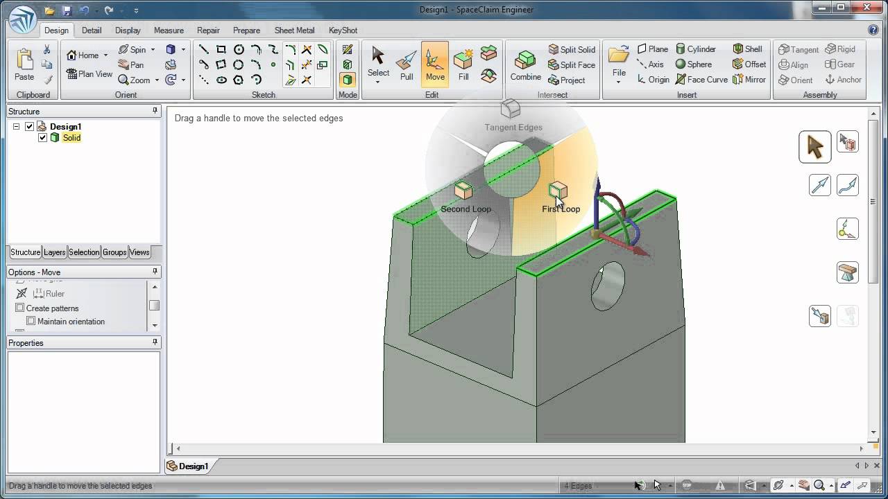
This video demonstrates how to efficiently perform electronics cooling simulations using ANSYS SpaceClaim for CAD geometry preparation and ANSYS Icepak for thermal analysis, enabling rapid design exploration and optimization through parametric modeling of heat sinks, fans, and grills to evaluate trade-offs between cooling performance and component costs.
ANSYS Icepak & SpaceClaim: Fast Electronics Cooling CFD Workflow
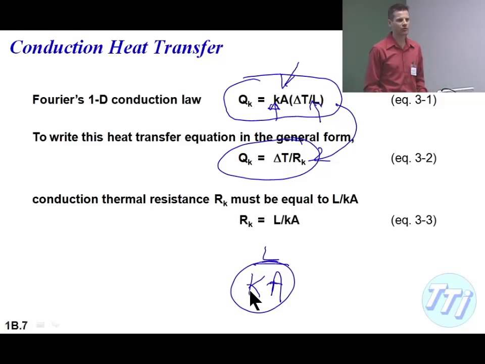
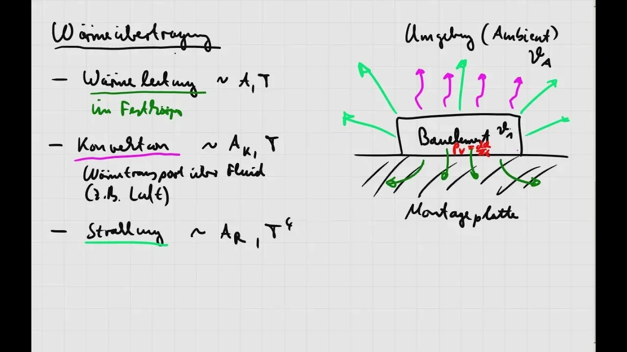
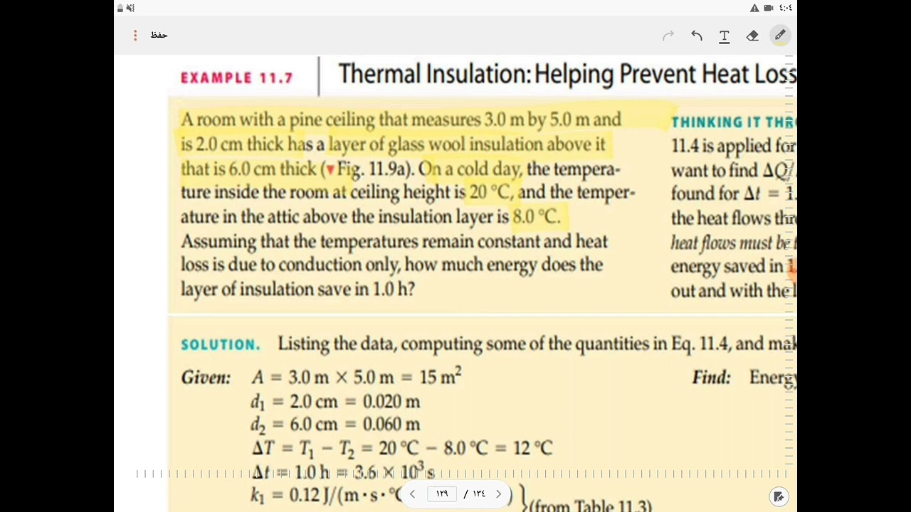
Added:Fundamental principles of heat transfer, specifically conduction, convection (natural and forced), and radiation in electronic systems.
Basic Computational Fluid Dynamics (CFD) concepts, including governing equations, boundary conditions, and the importance of mesh generation.
Introduction to 3D CAD modeling concepts and direct modeling workflows, as utilized in geometry preparation tools like SpaceClaim.
Understanding of electronics packaging components, such as PCBs, integrated circuits (ICs), heat sinks, thermal interface materials (TIMs), and fans.
Advanced meshing strategies in ANSYS Icepak, including non-conformal meshing, multi-level meshing, and conducting mesh independence studies.
Transient thermal analysis to simulate time-dependent heating behaviors, duty cycles, and thermal throttling in electronics.
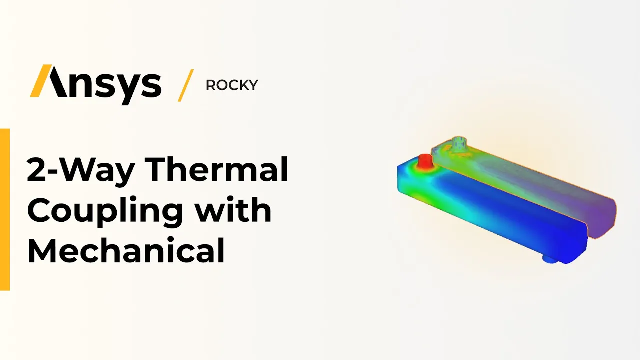
Multiphysics co-simulation, such as coupling ANSYS Icepak with ANSYS Mechanical for thermal-structural stress and warpage analysis.
Design of Experiments (DoE) and parametric optimization using ANSYS DesignXplorer to automatically optimize heat sink geometries and fan placement.
Experimental validation methodologies, including correlating CFD simulation results with physical wind tunnel testing and infrared thermography.
61K views522likes19:38Original Release: 2018-12-05
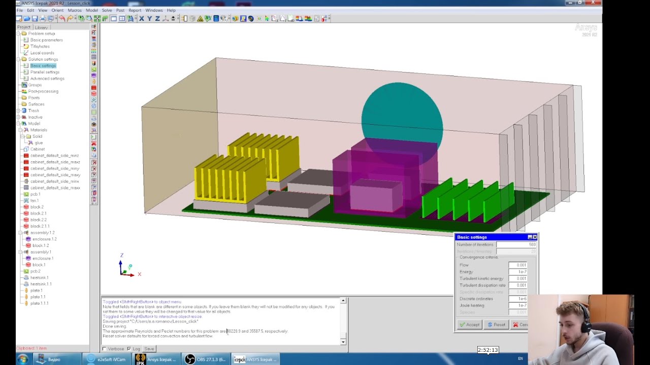
[Music] hi my name is Ming Yao and this will be a demonstration of Anna's ice pack and how to do electronics cooling really fast so today most electronics Cooling's problem starts with a CAD models we're gonna use answer space claim to prepare that model for analysis the big challenge of electronics cooling is that typically the jump is very complex you have multiple boards lots and lots of components grills he sinks fans etc so to treat a model like that efficiently we need some specialized tools and space claim and combined with ice pack is just the right tool to solve this problem quickly first of all space claim allows you to quickly can clean up the geometry so we can go ahead and for example get rid of the heat sinks on top of this chassis with a fill operation then we can start simplifying this model and preparing it for analysis for example we can select there's there's some grills here so I'm going to work from the outside inwards here under the workbench tab we can specify that this surface has grills on it and you'll create a rectangular box where it's the things the grill is and that's how we need for this surface here then we want to simplify the chassis so let's go ahead and do simplify and we can do a cuboid fit of the chassis components and at any time we can go and show just the non icepack object so these are the things that are still to be converted to ice pack objects one get real good rid of this heat sink here because we're gonna use some parametric operations to model heat sink and get some get an idea of how things behave when we change the size and shape of heat sinks here we have a fan and we're gonna select one of the hubs and that then creates these fan on Jax okay these fans are no longer needed have a few things here so we can first define this PCB this PVC this PCB is not a simple board so we're gonna use the polygon oufit and its extrude it in the z-axis so I'm gonna click on that it turns this PCB into a polygon and then we have some blocks and boxes remaining so we'll do simplify turn them into Q boys and cylinders and I think that's it we can use the grill object or the cat to model the grill in this case we're going to keep the grill object because this allows us to change the percentage of opening very easily and that allows optimisation so what we did here is we moved the grill object and then deleted the cat object so still have the grill in front these other boxes whistles we will be accurately modeled probably don't need this little piece here so now we have a model that's ready for analysis the components have been converted into ice pack objects so ice pack will recognize what they are and now we can start working on the ice pack portion of this project drag and drop an ice pack onto our space claim geometry and we can bring the model in and it will be prepared for analysis you can see that we have all of the components to find as this knows that these are fans and casings so there's a few things we can do here we have some regular fan sizes and if we want to adjust the fan you can see that we can put in various properties for a flow rate pressure you can do a non linear fan curve or fixed flow rate what I'm gonna do is I'm going to import some bringing some fans from our library so let's look at fans and there's a large number of different size of fans over here for example this fan is roughly the right size as the ones we have and the nice thing about this is that it will have the right characteristics already defined so I'm gonna add a couple of those things in there now I have two more fans if we look at the fans we've created here is Scott already a fan curve predefined by the manufacturer so we know that it's gonna behave appropriately this fan will be a Y Z fan we'll use the align tools to align the center of this fan to the fan from the CAD here and then we can adjust this one also Y Z then line it up along the center okay so we got two fans attached to the grill so we don't need these component 11 or 12 anymore now the fans right now are on the inside of the casing so we want to move this to the outside and that's easily done here grab this fan and the Y acts in the x-axis we want this to start on the outside okay so now our fans are correct let's take a look at our grill so this is a grill that was defined for us right now the free area ratio is 0.45 it tells us what the loss coefficient is we can look at different types of resistance types whether it's in vents bare metal wire screens or two playing screens different other many different other options to characterize it too but we'll leave it as default so that we have a fan here remember we remove the heatsink so now we want to put a heat sink in there and the benefit of adding a heat sink manually here especially a detailed heatsink is that we can control the number of fins the size of the fins and all the rest of it very easily so this heatsink is oriented in the XY direction and we can just put it on top of this this package here so the Z is going to be on the top surface the X will start over here go over here and the Y will end over here and start over here okay inside we have some packages and such but the nice thing about the heatsink here is now we can pressurize and adjust the thickness and the the fin count so maybe we want eight fins and we want the overall height to be a little bit higher 10 centimeters and it's definitely pointing in the wrong direction so let's adjust the that's just the orientation of our heat sink okay and this allows us model simplified heats things we can so easily create more complex eating heat sinks from CAD but then running parametric analysis on that becomes more challenging so let's look at our package here so this is our APU die I'm gonna have this pump out let's say 20 watts and we can go in and assign all the rest of the materials to here isn't the PCB now the PCB is solemn material I'll set it to fr 4 we have various ways of modeling boards more accurately by including the copper content and assigning properties you can also specify a PCB here from the circuit board and we have fully setup simulation we can go in and change the properties of some of these components before we start the simulation we want to use the problem setup wizard to define what's going to be in this analysis it'll be a force flow problem let's say some turbulence add it in and once that's done we can go ahead and start the analysis try to run this 400 iterations we do want to paralyze this so right now four cores let's go ahead and run this simulation all right the simulations completed we can review the results look at the temperature for each of the components here the maximum components for some of the bores and packages goes up to about 62 degrees we can plot the temperature you can slide this up and down to look at different locations we can also take a look at the velocity or the speed so you can see the way the flow comes out of the fan and impinges on the heat things we can run this for longer to fully converge I can do monitor plots to ensure that the temperatures are correct so let's deactivate this now we can see what happens when we change the size and of the heat sink and maybe the amount of temperature inputted so let's go find our heat sink here he thinks becomes very easy to parameterize in space in ice pack we can specify for example the number of of fins fin count so just putting a little a dollar sign in front of it turns this into a parameter we can make the overall height of this a parameter one centimeter so if we adjust the size of the fins that could be of interest let's see what are the impacts of adjusting the resistance free area ratio of the grill so have the same fan we can perhaps adjust the sizing of the fan and maybe adjust the fan curves a little bit but I'm gonna leave that set up as default so once that's done we can start looking at adding some so we have a couple of input 3d input parameters now the size of the fin and the area ratio here and we can also add in the Sun alpha parameter so we certainly want global temperature to be an output parameter so I think that's the only one we want to use got one more on the die itself we can maybe it adjust the die power level so do a power to see what kind of how much energy we can get rid of in this model and keep it below a certain temperature to turn certain type hour so once this is done I prefer to use the workbench optimization method so we got four input parameters one output parameter export this to workbench and we're done so once we have that export to workbench we have a friend reset with a set of input parameters and our output parameter that's not defined yet what point has a nice set of responsiveness optimization tools which I like to use to explore the design so let's say we have some functions we want to try it so the thin count we want to vary this anywhere between 4 and say 16 height so 5 to 2 centimeters on adjust a free area ratio between let's say 2 and 0.8 and power we want to investigate what happens when we have a 10 watt power source or 40 watt power source so this one allows me to do a preview of the data here Isis will generate a design of experiment now the thing with this is that the think I needs me integer you can see that all of my it doesn't make sense to have five point seven eight cent fins so instead of using a central composite approach I'm gonna do this as a custom approach and I'm just going to put things that's near to where the values are but now they're integers and now the simulation will run properly we can adjust the fin height grill and the power as as decimal values so when I hit run here it's going to go through all 25 simulations and report back on the temperature of each now that the simulation is finished we have 25 sets of data we can then do some processing to see what the data can tell us about what's happening so we can do a response service fit this will provide us with a equation that interpolate across all of the data points we've generated we can look at how sensitive a particular temperature is to pin count fin height ratio Grill ratio and power 3d so this response surface looks very uneven it doesn't look as like a smooth response surface we probably should do additional simulations to further refine these type of response surfaces the methods that we use to characterize response surface is a minimal set using the central composite approach so we certainly want to to get accurate results we would want to do some addition of optimization let's take a look at the optimization we can select certain constraints and for one we want to minimize the temperature but we probably also want to minimize the fin height and minimize the fin counts so that we can get away with a cheap heatsink go with a screening method and we'll pull off the states of 3,000 designs okay so this is a much more fuller trade off lot we've got a frito front here the minimum temperature for samples we want we have between 10 and 40 watts so let's say we want to go first of all we want to ensure that our temperature is low so let's get rid of anything over 50 degrees we won't have a high power so maybe we want 30 watts of power potentially in this model and if I click on one of these it tells me that to do this type of model to get this performance we need a 37 millimeter thin with about 13 fins and that allows us to do keep the temperature under 50 degrees and have a power of 30 so this gives us a lot of options of looking through the model trying to pick up trade-offs if we have 20 watts as we mentioned earlier you can filter out those with higher power and now we can reduce the number of fins so let's say we want a minimum spin of we can we have a couple of options here from the simulation one is eleven fin 0.1 millimeter off version or we can have four fins and it's a much thicker fin fin height so a lot of different options available in this simulation and by doing design of experiments and understanding the trade-offs this gives us a lot more data certainly to do this accurately we want to refine our response surface by adding in you know response services we can do verification points and refinement points adding various designs to better quantify our design space and that allow us to pick the correct design and use optimization to understand the trade-offs between our various options that's a quick example of how to do a ice pack simulation for electronics cooling taking a modern CAD model and turn it into an ice pack ready simulation then we did some extra design optimization to look at how changing the heatsink sizing and various other friends effect allow us to optimize the model so thank you for your time and please if you enjoyed the video please like it and visit us sing there he is calm thank you [Music]
Up Next

14:01
How to Install and Run LLMs Locally with Ollama: A Complete Guide
@TechWithTim
687.6K views•2025-01-13

12:54
Triumph of Orthodoxy Icon: Byzantine Art & History Explained
@BenCallan
2.1K views•2024-08-06

9:49
FastAPI vs Flask vs Django: Choosing the Right Python Web Framework
@TechWithTim
302.5K views•2024-05-26

1:42
Game of Thrones Opening Credits: A Cinematic Analysis
@gameofthrones
46.3M views•2011-04-18
Related Study Plans & Knowledge Roadmaps
Structured learning paths in General & Interdisciplinary Studies
general-studies
Elevator Engineering: History, Physics & Cities
01From Hoists to Safety Brakes: The Dawn of Vertical Lift
02Hydraulic vs. Traction: The Engineering Physics of Elevators
03Modern Speed, Safety, and Algorithms
+ 2 more learning modules
12h5 modules
Explore Roadmap
general-studies
Rubber: Material Science, History & Geopolitics
01Origins of Natural Rubber & Mesoamerican History
02The Chemistry of Natural Rubber & Vulcanization
03The Geopolitics of the Rubber Boom & Colonization
+ 2 more learning modules
12h5 modules
Explore Roadmap
general-studies
Containerization: Evolution, Logistics & Trade
01Ancient Trade & Bulk Cargo: Amphorae to Barrels
02The Industrial Revolution & Cardboard Packaging
03The Containerization Revolution: Malcom McLean
+ 2 more learning modules
12h5 modules
Explore Roadmap
general-studies
Textile Tech: Evolution, Labor & Global Impact
01Pre-Industrial Textiles: Handloom & Cottage Industry
02Mechanization: The Spinning Jenny to the Power Loom
03The Factory System & Global Labor Transformation
+ 2 more learning modules
10h5 modules
Explore Roadmap