





















This video demonstrates how to assemble and program the Petoi Bittle robot dog kit, an open-source educational robotics project that uses an interlocking mechanism design with minimal screws, allowing users to build a programmable robot dog by connecting servos to a controller board, calibrating the IMU sensor for balance detection, and fine-tuning joint angles using a serial monitor interface with Arduino IDE.
Petoi Bittle Robot Dog Assembly and Servo Calibration Guide
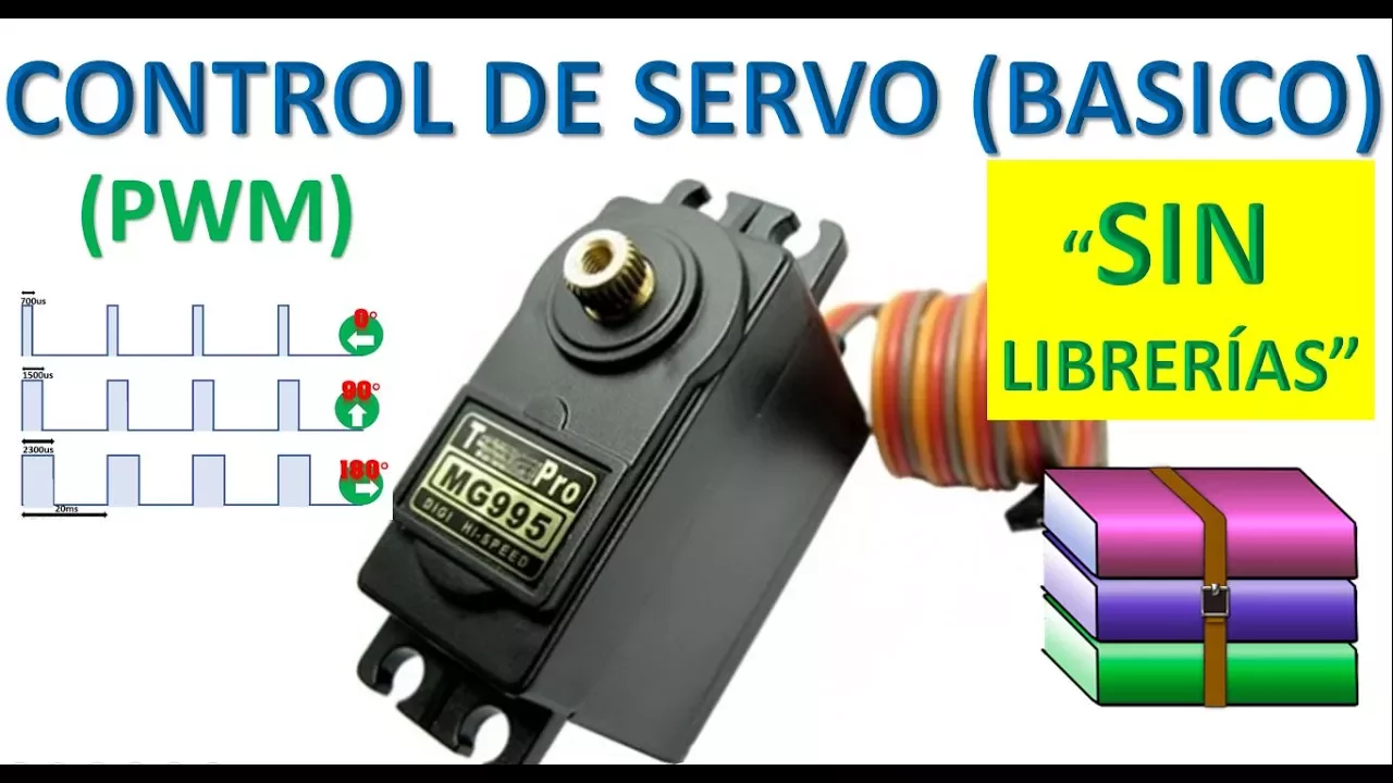
Added:Basic principles of servo motors, including Pulse Width Modulation (PWM) and angular positioning control.
Fundamentals of physical assembly, structural linkages, and Degrees of Freedom (DoF) in robotic limbs.
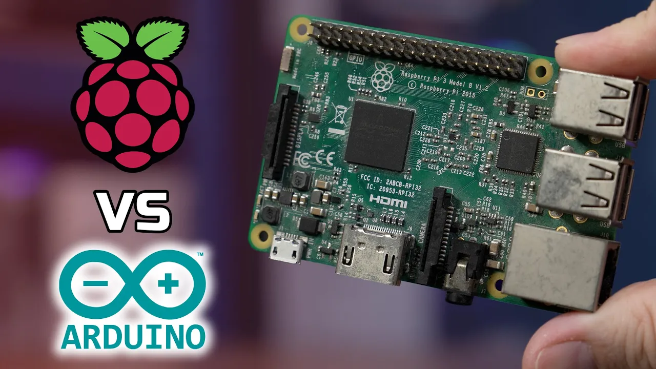
Introduction to microcontrollers (such as Arduino-compatible boards) and how they interface with peripheral devices.
Basic electrical safety and power management principles relevant to low-voltage consumer robotics.
Implementing Inverse Kinematics (IK) to coordinate multi-joint leg movements for stable walking gaits.
Integrating IMUs (Inertial Measurement Units) and feedback loops for active stabilization and fall recovery.
Developing autonomous behavior by interfacing external sensors (e.g., ultrasonic sensors, cameras) with the robot's mainboard.
Exploring advanced programming frameworks such as the Robot Operating System (ROS) or reinforcement learning for quadruped locomotion.
94.9K views1.1Klikes32:54Original Release: 2021-01-24
hello everyone how are you doing today i'm going to show you how to assemble beetle from the beetle kit so we have a box of servos a usb cable the body parts and nightboard and the remote in the server box we have 10 p1s servers specifically designed for beta among them five long cables and one of them is a spare unit and five short cable and these are the screws and springs for the circles this is the bag for connectors the uploader bluetooth jungle and wifi dongle and a tiny screwdriver just in case you don't have one at home the main body part is pre-assembled for packaging and shipping but let me show you how to open it use one finger to push one side of the cover and another finger to take it off easy and the battery is slided into this track it makes it easy to switch batteries and also help to change the center of mass because the heavier part of battery is in the front by sliding it you can shift the center mass backward you can even install the battery in a reverse direction so that you can tune the center mass from the front to the back it will help the robot to balance once you add more components to it and there's no screws in this main body part all parts are put together using the interlocking mechanism the hat is designed as a clip you can use it to hold some sensors ouch let's prepare the legs first you will need all these black pieces and the accessory bag in the servo box screws springs and solo arms before you start to make the upper legs observe the silver arms the two sides are different on one side it has teeth to hold the soles so that it can rotate and the longer part will be inserted into this track pay attention the teeth is on this side and bend it then push this is one part and for the other side it has an opposite direction you will use the side without the teeth this is with the teeth this is without the teeth and the longer piece inside insert it into the track hold it and bend it a little bit push now you can put these two pieces together next insert the springs hold the arm in this direction so that the yellow piece is facing you and pull the spring here and use your finger to push it over the step no it's in be careful with the springs it may jump over and fly everywhere this structure will help to reduce the shock on the servos you see how it works do the same operation for all the four legs to check whether the directions are correct you can take a look at all these alarms and the directions should be the same all of them will be able to accept this servo in this way now let's make the lower legs you need to be very careful with the directions because the left leg and the right leg are different first put all the components in this pattern let me show you how to make the right leg hold the servo in this way and organize the cable bend it in this direction not in this direction you see the difference bend it in this direction and hold it and notice there is a little window here on the lower leg is designed to let the wire go through this is one leg and this is another leg the front leg and back leg are the same now look at this left leg is using the same principle but the direction is opposite hold it insert it pull them back onto the table and check whether the directions are correct if everything looks fine you can put the screws in to fix them into the structure you will need these screws with a sharp ending [Music] so [Music] [Applause] foreign um now let's make the head you will need the servo with a short cable bend the cable in this way not this way you see the difference and to the left see also notice that the output shaft is towards the back of the head then use screws to fix it on the structure okay and then install the servo arm choose a neck again pay attention to the two different sides this piece will be able to accept the next circle so it should be facing upward then use two screws to fix them into the structure and by the way this neck is designed to be um flip on so it's very convenient to take it on and off so far so good within 10 minutes we are already as a step now we need to connect all these servos onto the controller board you will need four servos with shorter cables for the shoulder and insert them in this way pull the cable into the shoulder and pay attention to the direction of this output shaft you see this pattern these are pointing outward if you put it in this direction it will be wrong you see the difference the whole structure should be symmetric then insert the lower legs again pay attention to the front and back of the body notice these larger holes on this track this should be towards the tail if i put back this head you will see it clearly see and then put these lower legs through the hole under the shoulder and back into the body like this and don't forget the neck now you need to connect the cables onto the light board and pay attention to the direction this is the tail you need to connect the neck to the first pings on this side and the black cable in the ground also pay attention to the way you plug in one and then the shoulder this is a lower level the shoulder is here connect it to the third pin of this board and for the lower leg connected to the fourth pin here there is one gap between the peaks see and for all the other legs they are symmetric to this left front leg can you see the pattern we have some detailed pictures in our menu so if you cannot see it clearly you can refer to the pictures okay now all the cables are connected and all these wires should go in this pattern back to the board so now i'm trying to organize these cables see and this is the infrared receiver put it below the shoulder here make sure that the wires don't go underneath the plugs it should be flat then we can use the screws to fix the board onto the body make sure that all these wires are well organized so that later if you flip the cover on they will not be conflicting with the cover the next step will be uploading the code to the light board then we will be able to calibrate the servos for the final assembly oh and remember to install the screws on the shoulder we use arduino ide to program beetle you can download our sample code on github by searching opencat you will need these wired uploader or this bluetooth uploader to upload the code to beta when connecting pay attention to the pink numbers on the board and there are also the pin numbers on nightboard make sure that you are connecting them by the corresponding pin numbers for example the dtr should be connected to ddr and gnd should be connected to gnd now it's connected then we need to set up the programming environment and upload the bitter code onto beetle after setting up the arduino environment you can upload the write instinct sketch onto beta and you can open the serial monitor to set it up enter three y's capitalized wise and it will enter the calibration mode for the imu that's the sensor for detecting the body orientation make sure you are putting beetle on a flat table and don't touch it during this process wait until it beeps six times in one row okay calibration down now that the calibration is done we can go to the main code the opencad code again upload okay [Music] the beeping just indicates that the battery is not connected and you can connect this battery onto my board from here long press the button now the light board is powered by this battery and it's already doing some behavior okay because all the servos may be orienting to different directions you will need to enter the joint calibration mode to install all the legs we can use the remote to do that press the eq button which brings the robot into the calibration mode and then install all the legs and head at a right angle to the body it won't be perfect right angles and we will do fine tuning afterwards but for now just pull them all closest to the right angle like this so and if i press the walking button item is already alive then we need to fine tune all the joints then beta will be fully functional to fine-tune beto's joints you will need the computer and open the serial monitor of arduino ide enter c in the serial monitor to put beto into the calibration status and use this joint tuner as a reference to find the best calibration value put veto on the flat table and put the tuner besides the leg try to match the center of these two holes with the center of the two holes on this tuner if not enter the calibration commands in the serial monitor more details can be found on our beetle menu after calibrating beetle's joints now you can install these flat end screws and fix the servos [Music] yes so [Music] and install these covers to hide the wires also notice that these covers have directions it should be flat in parallel to the surface of this leg and in the end install the cover and the tail now we are done with sampling beetle long press the button and pito is alive greetings thanks for watching
Up Next

9:26
From Arduino to ESP32: A Comprehensive Beginner's Guide to Getting Started
@Robonyx
1.1M views•2024-03-12

12:54
Triumph of Orthodoxy Icon: Byzantine Art & History Explained
@BenCallan
2.1K views•2024-08-06

9:49
FastAPI vs Flask vs Django: Choosing the Right Python Web Framework
@TechWithTim
302.5K views•2024-05-26

1:42
Game of Thrones Opening Credits: A Cinematic Analysis
@gameofthrones
46.3M views•2011-04-18
Related Study Plans & Knowledge Roadmaps
Structured learning paths in General & Interdisciplinary Studies
general-studies
Elevator Engineering: History, Physics & Cities
01From Hoists to Safety Brakes: The Dawn of Vertical Lift
02Hydraulic vs. Traction: The Engineering Physics of Elevators
03Modern Speed, Safety, and Algorithms
+ 2 more learning modules
12h5 modules
Explore Roadmap
general-studies
Rubber: Material Science, History & Geopolitics
01Origins of Natural Rubber & Mesoamerican History
02The Chemistry of Natural Rubber & Vulcanization
03The Geopolitics of the Rubber Boom & Colonization
+ 2 more learning modules
12h5 modules
Explore Roadmap
general-studies
Containerization: Evolution, Logistics & Trade
01Ancient Trade & Bulk Cargo: Amphorae to Barrels
02The Industrial Revolution & Cardboard Packaging
03The Containerization Revolution: Malcom McLean
+ 2 more learning modules
12h5 modules
Explore Roadmap
general-studies
Textile Tech: Evolution, Labor & Global Impact
01Pre-Industrial Textiles: Handloom & Cottage Industry
02Mechanization: The Spinning Jenny to the Power Loom
03The Factory System & Global Labor Transformation
+ 2 more learning modules
10h5 modules
Explore Roadmap