

![[Tutorial] Cómo cargar o instalar librerias en Arduino](https://i.ytimg.com/vi/NAaWn0sA21U/hqdefault.jpg)



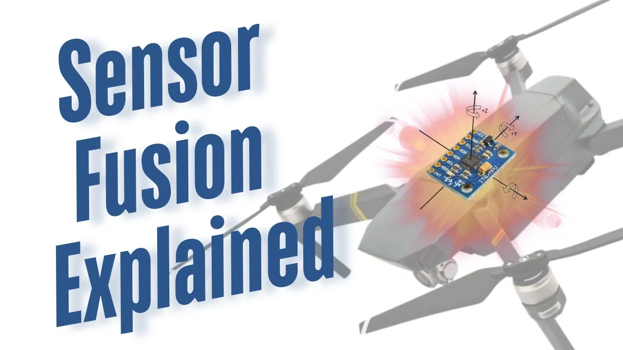

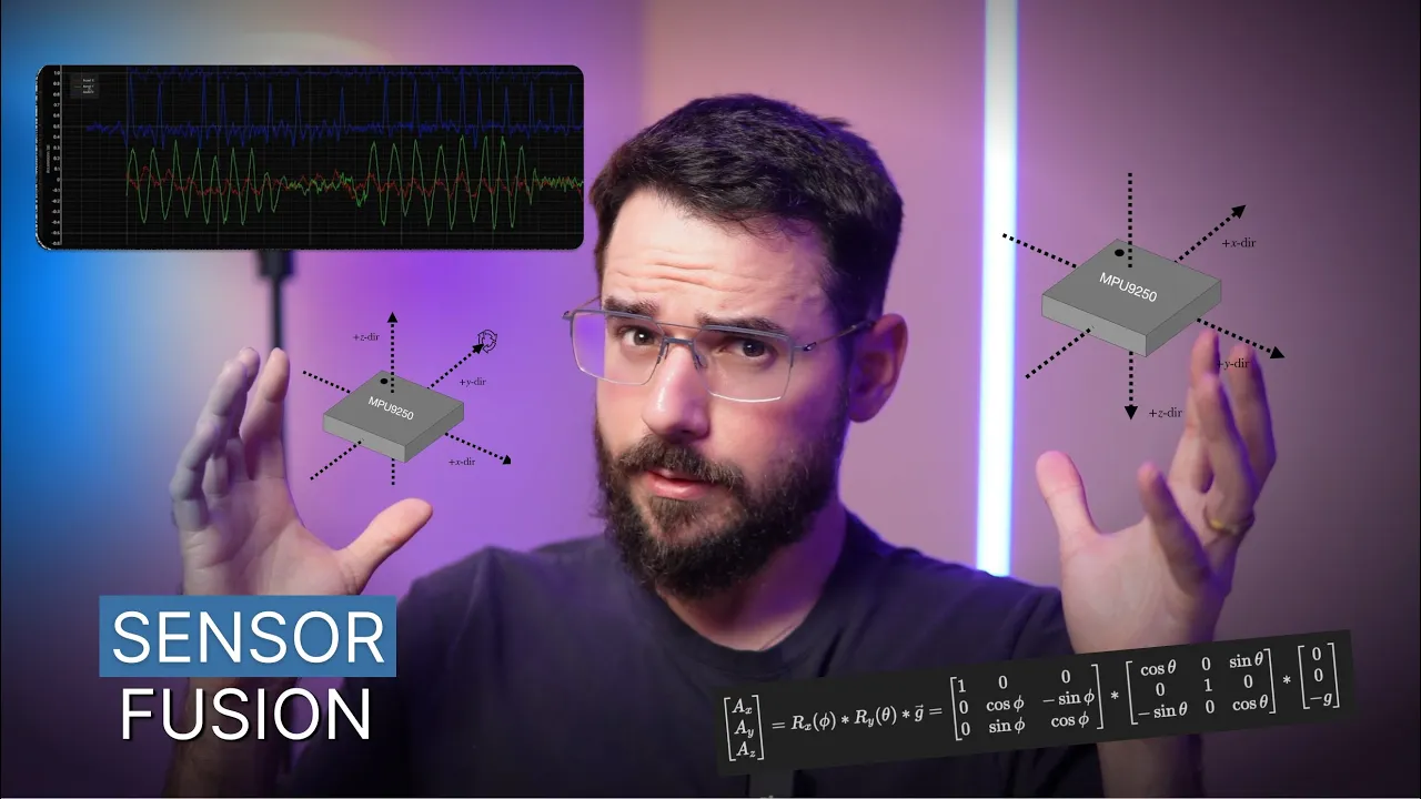


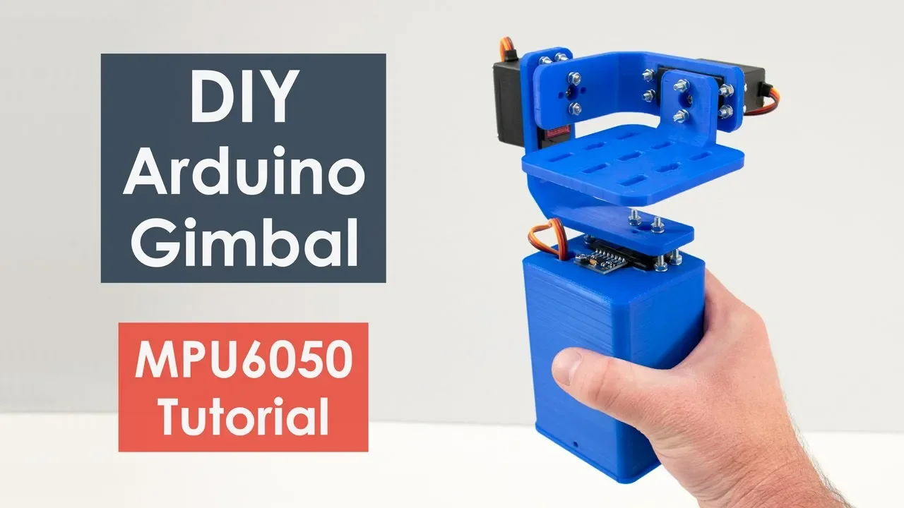

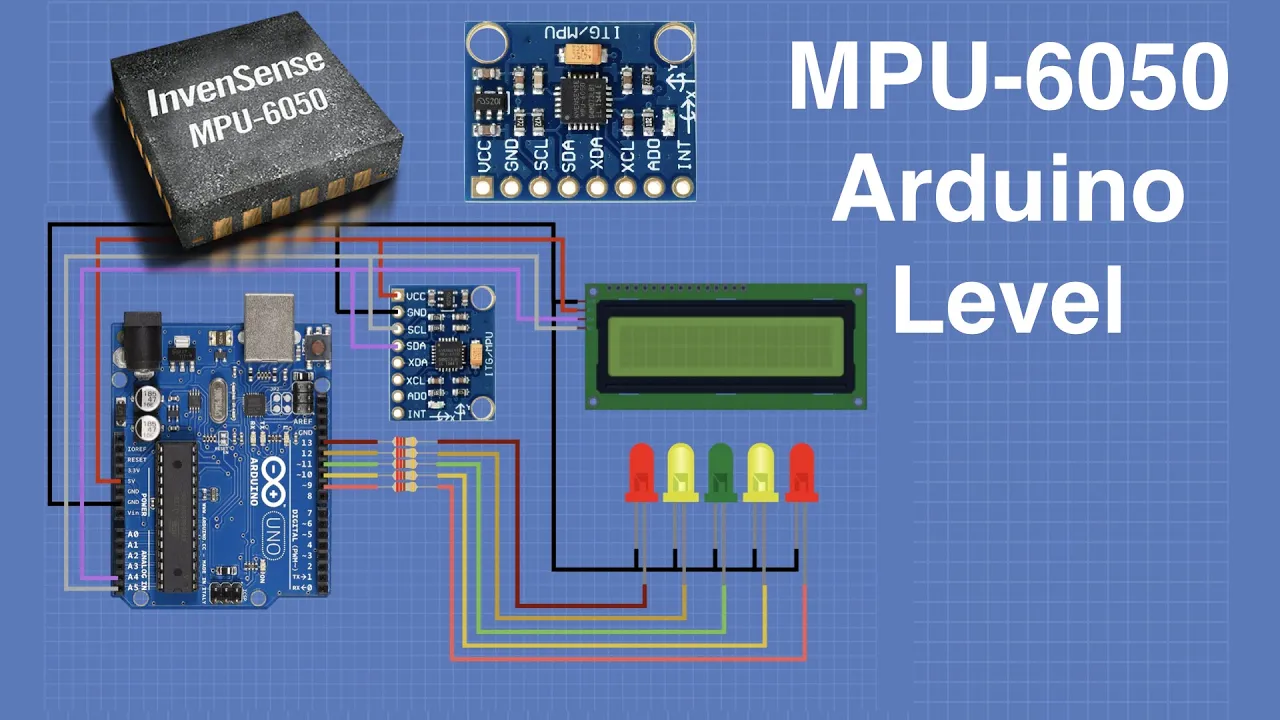


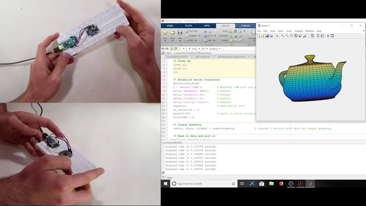

The MPU6050 (GY-521) is a 6-degree-of-freedom sensor module combining a 3-axis accelerometer and 3-axis gyroscope, capable of measuring linear acceleration (±2g to ±16g range) and rotational velocity (±250 to ±2000 dps range). It connects to Arduino via I2C interface using VCC, GND, SCL, and SDA pins, with optional interrupt pin for motion detection. The sensor data can be read through the MPU6050 library in Arduino IDE, providing outputs like Euler angles (roll, pitch, yaw) and acceleration values. For 3D visualization, the sensor data can be processed in Processing IDE using the toxiclibs library to create real-time 3D models that mirror the sensor's physical orientation, demonstrating how sensor fusion of accelerometer and gyroscope data enables accurate motion tracking and spatial orientation determination.
MPU6050 Arduino GY-521 Sensor Tutorial: Wiring and Code Overview
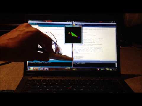
Added:hello and welcome to another diy engineers video in this video i'll be going over the mpu 6050 module which has this three axis accelerometer and a three axis gyroscope all in one meaning it can measure accelerations on the x y and z axis and also measure rotational velocity along those same axis in the video we'll be covering the sensor pins and directions how to connect it to the arduino uno programming arduino testing an arduino and even doing a 3d modeling simulation to show what the sensor is reading as you move it so if you're interested please join us for the rest of the video let's get started so now let's talk about the mpu-6060 module and the main parameters it has an accelerometer range that can go from plus or minus 2g to plus or minus 4g or you can also run a plus or minus aj or 16g or of course g is a gravitational constant which is 9.81 meters per second squared for the gyroscope which is also built into the module you can have it at a plus or minus 250 degrees per second plus or minus 500 1000 or 2000 all of them in degrees per second it has an input voltage of 3.3 volts all the way to 5 volts which means you can feed it with your arduino uno so now what are our pins it has eight pins we have vcc where we provide the power input ground for the ground which connects to the arduino ground then we have scl and sda for the i2c clock pin in your data pin and you also have xda and xcl for external i2c pins for data and clock you have a pin called ado which allows you to change the i2c address of the module in case you're running other things on i2c then you have an intro pin which allows it to wake up when never there's any action or something going on you can also see in the actual board you can see here there's a y and x axis shown by the right hand rule then you know that z will be up as i've shown here on this axis shown and then you have roll and pitch and yaw relative to those axes here's how you would connect it to the arduino uno we actually in this example are only showing five inputs connected because we're not using the external i2c pins or we're not changing the i2c address so we first have vcc connected to five volts in the arduino uno we have ground connected to ground scl is connected to the sel pin and sda is connected to the sda pin and then we have the interrupt which we're connecting to digital input output number two on the arduino so now the next step is to go ahead open arduino and let's install the required library to do that you go to sketch include library and then click on manage libraries you then want to go ahead to the search bar and type mpu6050 the one you're interested is in this one which i already have installed all you would have to do is select and click install i won't do it since i already have it so once you do the next thing you want to do is go to file example and go to mpu6050 and click on mpu6050dmp6 and this will open the main example that we're going to be using for this so to start using this example from the library all we have to do is scroll down to the section where we define what outputs we want so in here we have the quartens we have the euler angles url pitch which is turned on by default we have real acceleration world acceleration and the teapot which is for 3d visualization in this case we have draw pitch roll already turned on all we're going to do is uncomment this one so that we can get the real acceleration and if you read it the lines or the comments above says you know to uncomment that if you want the acceleration with gravity removed this will be acceleration within the reference frame basically of the accelerometer so x plus will always be x plus regardless of the way this sensor is looking at which means that we're we're recording and outputting the acceleration from the sensors frame of reference if you want something different then take a look at output readable world acceleration which basically will adjust the output such that the frame of reference is relative to the world and not relative to the sensor so with that we can go ahead and send this code to the arduino so we can test the sensor so let's go ahead and press upload now we're download loading we can go ahead and open this serial monitor and you're required to enter an input here and then press enter so for a second i'm just going to stop the auto scroll so you can see this is essentially giving you acceleration and then this is the jar roll pitch angle the angle is presented in degrees relative to the original orientation so anything you see here can be minor noise and this is actually supposed to be a value that can go from negative 32 750 to positive 32 750 where that is just the numeric value and how much sensitivity just depends if you pick the option for 2g 4g 8g or 16g that we talked about earlier or 1g equals 9.81 meters per second square or 32.19 feet per second square the default setting for acceleration is 2g basically this means barely no acceleration now i'll go ahead and turn on the autoscroll again we can go to the bottom and you can see that if i change now the orientation we're seeing some accelerations as i move it and also some different angles so now let's go ahead and change the code to perform some 3d model visualization using processing ide all we got to do is go to the same section that we edited before we will comment the line that we had been using before to get the jaw roll pitch angle and degrees same thing for acceleration and we uncomment this one that says output teapot so with that just go ahead and upload the code okay so now we're ready from the arduino standpoint all we have to do now is install processing ide laserized code on processing ide and run it so we can visualize the orientation of our sensor now i left the link in the description to take you to the processing ide download page click it and once you get there make sure to click the link to the operating system that you own for me it'll be windows 64-bit which i will click to start my download once fully downloaded go ahead and click to extract all the files this will take some time so now open the folder and double click on processing ide to start the program then all you got to do is start to import the required library so go to sketch import and import library which will open the contributions manager in there you need to type toxic and then pick toxic libs to install the toxic library once you click install it will start downloading and then it will start installing showing on fast forward so you don't have to wait forever for it to install once completely installed it will show as installed and then on the top row where it says status eventually you will see green check mark showing fully installed so now that you have all required libraries for processing ide you have to open the required file to run the 3d visualization so go to file open and you need to go to the right location of the arduino folder that contains the library for mpu6050 and find this file so you can see here that for me is on my pc then documents arduino and then from there on once you get to your main arduino file is libraries mpu6050 examples mpu6050 dmp6 processing mpu teapot and then you select this file this is it and once you get here all you have to do is then click run will take a little bit and then it will show a window with the 3d model all right so now you can see the output of processing ide and a video of me moving the accelerometer through a 3d printed part that looks like an airplane so you can see that as i move it in space processing ide mimics the shape and the orientation of such shape in space i move it up and down or sideways and it also goes along with it so you can see that the mpu6050 is processing the angles pretty well and keeping up with it through the integration of the gyroscope and accelerometer to keep you know track of motion so i hope you guys enjoyed this if you did please consider subscribing and giving us a thumbs up thank you very much and see you in the next one bye
Up Next

TB6600 Stepper Motor Driver with Arduino: NEMA 17/23 Guide
@mytectutor
192.8K views•2022-02-02

Triumph of Orthodoxy Icon: Byzantine Art & History Explained
@BenCallan
2.1K views•2024-08-06
GRBL and Arduino CNC Shield Setup Guide for Beginners
@diyengineers
264.6K views•2023-01-05

Game of Thrones Opening Credits: A Cinematic Analysis
@gameofthrones
46.3M views•2011-04-18
Related Study Plans & Knowledge Roadmaps
Structured learning paths in General & Interdisciplinary Studies