

















This video demonstrates how to build a simple ECG circuit using an instrumentation amplifier constructed from three 741 operational amplifiers, featuring resistor values R1=100kΩ, R2=5.1kΩ, R3=82kΩ, and R_gain=5.1kΩ, along with RC filters for signal conditioning, and shows how to connect electrodes to capture heart signals.
DIY Electrocardiography Circuit Using Op-Amps | ECG Amplifier Design
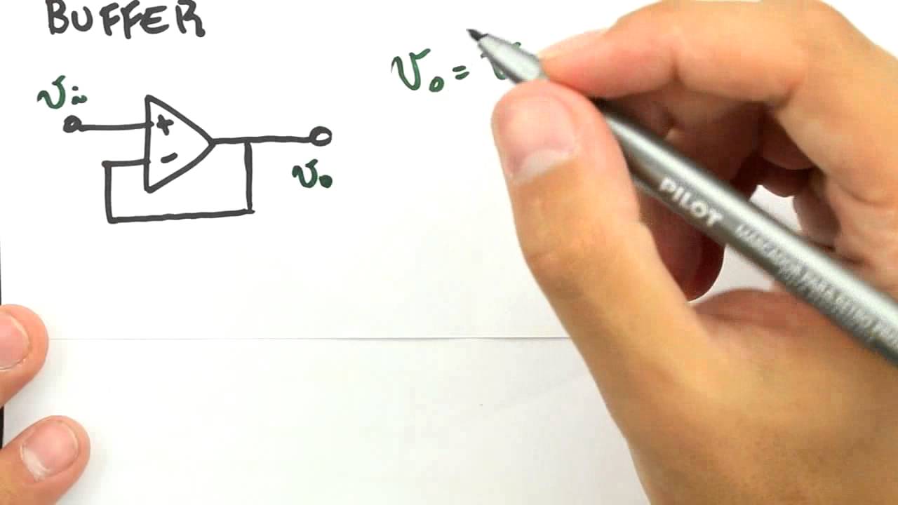
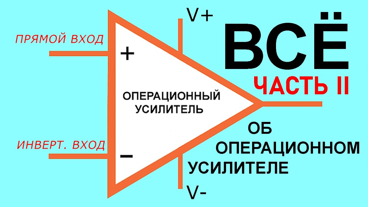
Added:Basic Operational Amplifier (Op-Amp) theory, including inverting, non-inverting, and differential amplifier configurations.
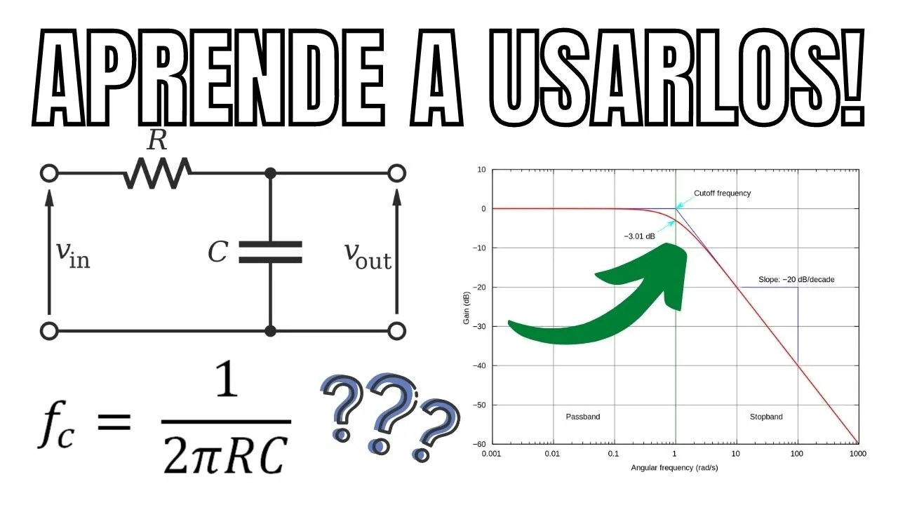
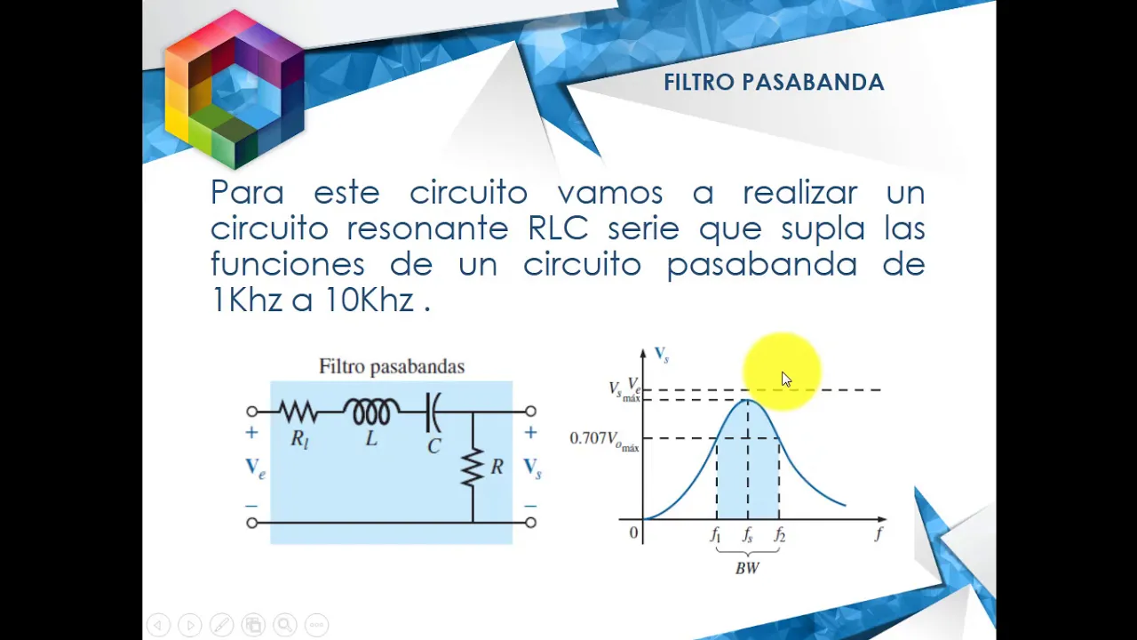
Fundamentals of analog filter design, specifically active and passive low-pass and high-pass RC filters.
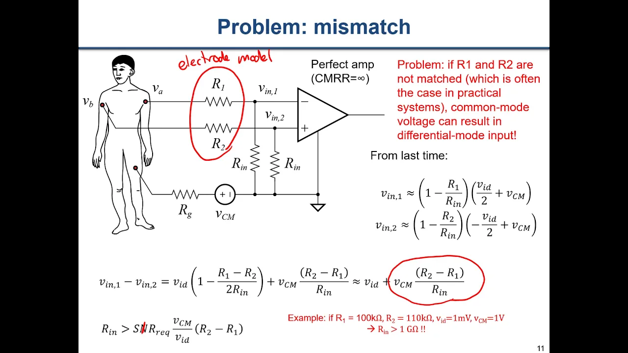
The concept of Common Mode Rejection Ratio (CMRR) and the architecture of a classic 3-op-amp instrumentation amplifier.
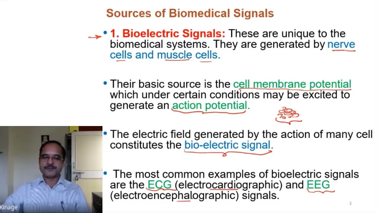
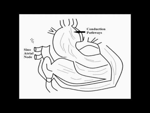
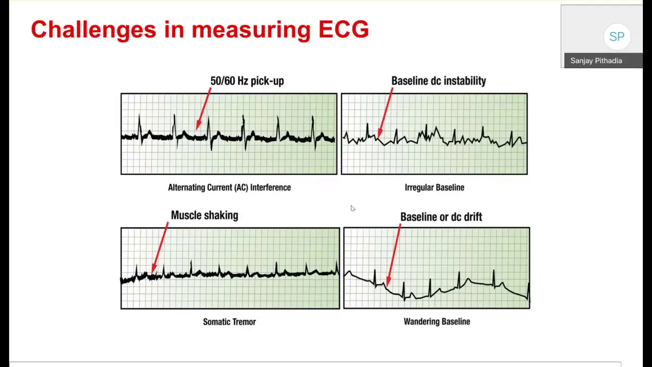
Characteristics of biopotential signals (such as ECG), including their typical amplitude range (millivolts) and frequency spectrum (0.05 Hz to 150 Hz).
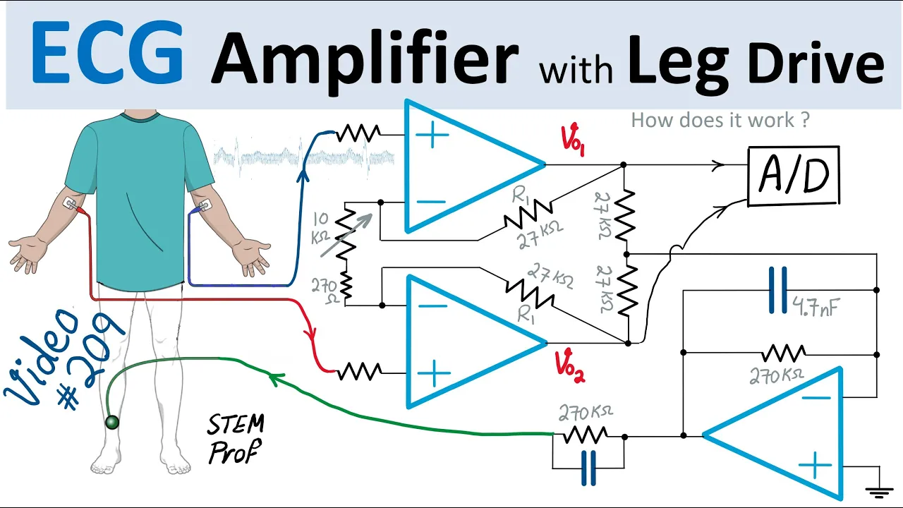
Implementation of Right Leg Drive (RLD) circuitry to actively reduce common-mode noise and power-line interference.
Analog-to-Digital Conversion (ADC) and interfacing the analog ECG front-end with microcontrollers (e.g., Arduino, ESP32) for data acquisition.
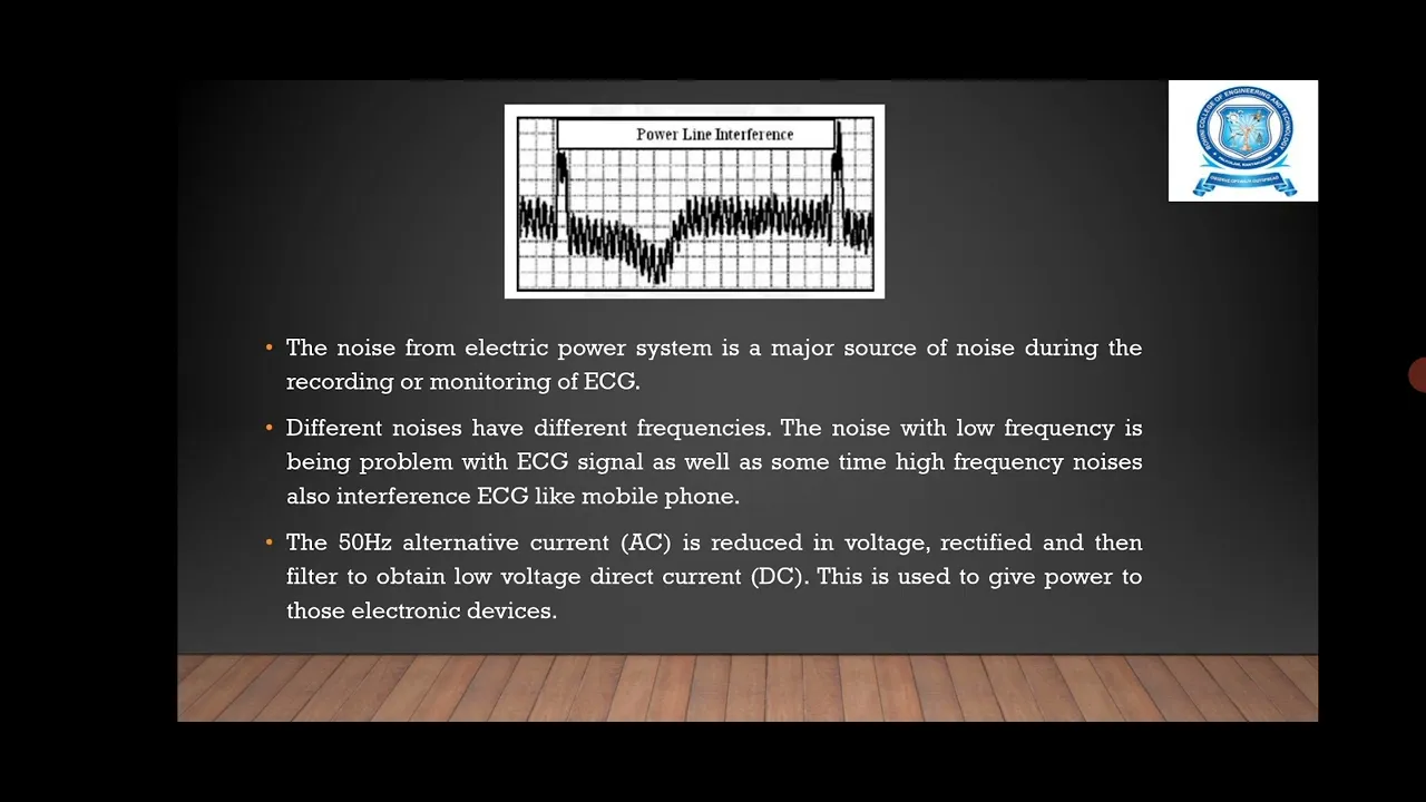
Digital Signal Processing (DSP) techniques, such as designing digital notch filters to eliminate 50/60 Hz electrical mains noise.
Electrical safety standards for medical devices (such as IEC 60601-1) and the use of isolation amplifiers to ensure patient safety.
26.3K views523likes10:24Original Release: 2023-11-21
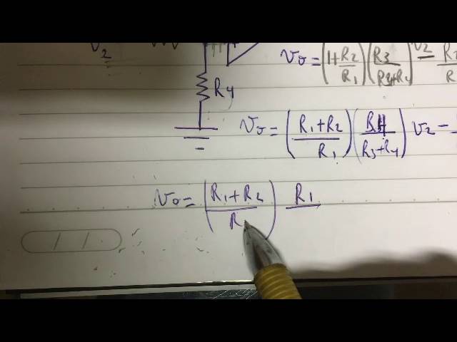
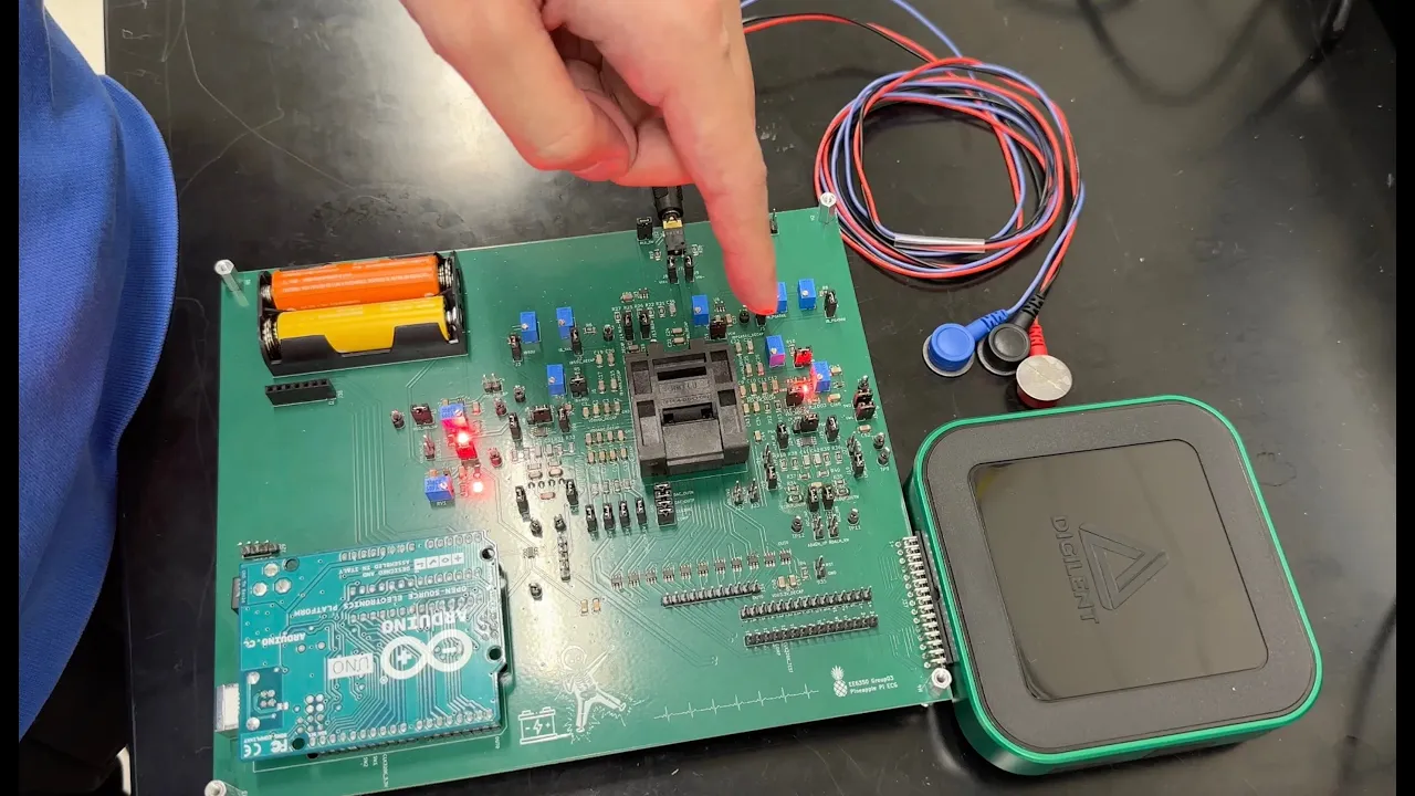
in this video I'm going to implement this instrumentation amplifier and I'm going to look at my ECG signal so as you can see I prepared the resistors for uh this design and I picked my R3 to be 82k and my R gain is 5K my R2 is 5K as well 5.1 K all of them 5.1 R1 is 100k okay so the first step would be to double check that the values of of the resistors are correct that you didn't mess up the colors and then we have these uh 741 up amps also you need to remember that you read the up and Pen one uh from the dot okay as you can see there's a little circle there a DOT that's that's signifying node number one so now I'm going to start placing my components uh make sure to place the up amp here across this Gap so that you don't short the uh pins okay so you put one and make sure when you place it don't bend its legs make sure uh place it properly um over those G uh those uh slots and then just press gently from one side to the other let me make sure that I did it okay and then I'm going to put the other one I can't see the dot okay here is the dot okay again wiggle it and don't bend its uh leg and then the final one here so I'm going to put it in a way that looks like the schematics that I showed you earlier why because I want to be able to debug easily if I had an issue okay so now I have all of my three up amps uh connected on the board now the next step is to power the up amps okay so let's power the up amps you should know that pen number four is the minus 15 pin so four and then two minus5 this is five this is ground and this is minus5 and then I'm going to do the same for this one and this one I did a little trick here to make my Circuit look neat I connected all of the minus 15s together okay so that I don't have like like a long wire extending to here and then another one to here just one to -5 make sure it's -5 yes and then you can power the others from this guy and so you know that 15 is supposed to go to pin number seven so this is 1 2 3 4 5 6 and seven just going to connect this seven with this seven you don't need to do that but this is making my Circuit look neat and the seven with this seven and then finally this seven with 15 let's start connecting the resistors from the first up amp from pin number six there's the 100K which is my R1 R1 goes to anywhere [Music] here and then R1 is connected to our gain which is for me 5.1 so let's put that [Music] 5.1 okay don't make them touch and then again our gain is connected to the other R1 which goes to pin six off the lower up amp okay there is a wire that goes [Music] from the minus pin then the inverting pin which is pin two it goes to where it goes to the leg of R again that is connected to r one which is this one and then the same for this op amp from pin two to this leg of our again which is connected to the R1 of the first up app next is R2 which is connected from pin six which is this guy here to where to a node after that it's connected to R3 which is this [Music] one okay it's hard to see through the camera and then I'm just going to put it here anywhere and then connect it to ground let me put the ground in yellow this is our ground this one from pen three a wire goes to uh be in between R2 and R3 here so I'm just going to do it in which color I'm going to do it in Black it doesn't matter the color it's just that use Cutters to make debugging easier and so this goes with this node and then pin number two of the last of M goes to between R2 and R3 of this op M but we haven't connected R2 and R3 so let's do it R2 is connected to pin six which is this okay and then connect R3 and then this R3 is not connected to ground like the other one it's connected to V out of this up amp which is pin six can we reach yes we can so if you don't have to use wires don't use wires so you don't need to use a wire for example from this guy to six okay so just like put the resistor in we have this one hanging so and this one surprisingly okay so this the 2 one goes to here make sure yes and this one goes between R2 and R3 here s yes so this one between R2 and R3 here which is pin three which is the non-inverting input of this up M with with this guy doing the same but with the inverting input of the up AR it goes between R2 and R3 in addition to my instrumentation amplifier I'm going to do an RC filter a low pass filter from the output of the last up amp I'm going to take this resistor and put it here and then a [Music] capacitor the output here and then this capacitor needs to be grounded so I did a low pass filter here and I'm taking the output from here from between the uh resistor and capacitor and this is connected to channel ai0 plus and the minus is connected to ground the output of this filter which is right here between the resistor and the capacitor is taken to a CR circuit which is a high pass filter as you can see here and then this is the C this is the C and this is the r of the CR uh highpass filter and then the output of that is this wire right here which is uh the signal after going through the high pass and the low pass and then you're going to connect it to your scope I have here wipes and electroids so I'm going to wipe the skin first and then connect the electroid and these are the wires that I'm going to clip to the El RS and these ends will go into the circuit and then you're going to connect your right hand to V1 your left hand to V2 and your right leg to uh instead of the ground in R3 and then you'll get the signal like this it's a straightforward implementation I hope you now know how to do it
Up Next

25:08
Repairing an E&L Instruments Breadboard: Sines, Oscillation Faults & Component Choices
@CuriousMarc
43.9K views•2022-03-17

30:32
Ultrasonic Transducers: Resonant Frequency Measurement and Horn Design
@imajeenyus42
229.9K views•2017-02-22

54:16
Polymer Environmental Degradation: Mechanisms & Stabilization
@iit
1.8K views•2012-07-10

33:39
How a Student's Question Saved a NYC Skyscraper from Collapse
@veritasium
22.8M views•2025-04-26
Related Study Plans & Knowledge Roadmaps
Structured learning paths in Engineering
engineering
Building Acoustic Levitators: Physics & Arduino
01The Physics of Sound and Standing Waves
02Piezoelectric Transducers and H-Bridge Drivers
03Arduino Programming: Generating 40 kHz Signals
+ 2 more learning modules
14h5 modules
Explore Roadmap
engineering
Building Peltier Cloud Chambers: Particle Tracks
01Cosmic Rays & Cloud Chamber Physics
02Thermoelectric Cooling (TEC) Fundamentals
03Custom Liquid-Cooling Loop Design
+ 2 more learning modules
18h5 modules
Explore Roadmap
engineering
Yagi-Uda Antennas: Modeling, Build & VNA Test
01Introduction to RF and Antenna Fundamentals
02Yagi-Uda Antenna Design Principles
03Antenna Modeling and Simulation in 4NEC2
+ 2 more learning modules
18h5 modules
Explore Roadmap
engineering
ECG Monitor Design: Op-Amps, Filters & Noise
01Electronics & Breadboard Basics
02Op-Amps and Instrumentation Amplifiers
03Bioelectricity and ECG Fundamentals
+ 2 more learning modules
18h5 modules
Explore Roadmap