



















In analog circuits with feedback loops, transistors must have matching turn-off times to prevent oscillation; even transistors with similar transition frequencies (250 MHz) can cause instability if their turn-off times differ significantly (18 nanoseconds vs. longer), as demonstrated when replacing a vintage 400 MHz transistor in a function generator's comparator buffer circuit caused the circuit to oscillate at high frequencies.
Repairing an E&L Instruments Breadboard: Sines, Oscillation Faults & Component Choices
Added:Fundamental understanding of analog circuits, specifically operational amplifiers (op-amps) and how comparators function.
Basic proficiency with electronics lab equipment, particularly using an oscilloscope to analyze waveforms and detect signal noise.
Knowledge of feedback theory, including positive and negative feedback loops, and how they relate to circuit stability and oscillation.
Familiarity with passive electronic components (resistors, capacitors, inductors) and how aging affects their nominal values and parasitic characteristics.
Advanced signal integrity and printed circuit board (PCB) layout techniques to prevent parasitic oscillations in high-speed analog designs.
In-depth study of active filter design and sine wave generation circuits (such as Wien-bridge oscillators) for precision instrumentation.
Methods for diagnosing and repairing vintage test equipment, including component sourcing strategies for obsolete semiconductors like the LM710.
Exploration of high-speed comparator applications and decoupling techniques to ensure stability in noisy electrical environments.
43.9K views3Klikes25:08Original Release: 2022-03-17
Hello. I like breadboards. And to complete my E&L Industries breadboard system collection, I bought this monster one on eBay. It cost $1300 in 1971, which is almost $10,000 in today’s money.
In additions to its 4 breadboards, many switches and lights, it promises to have 3 variable power supplies, a full function generator and a pulser.
It was pretty banged up, and we had to do quite a bit of electro-mechanical repairs in the first episode. It took a long second episode to resurrect the power supplies and the function generator. Well, not quite. After much effort and many a transistor change, we finally have a square wave and a triangle wave. But the sine wave is still eluding us. And as you’ll see, it won’t be the only thing eluding us either.
Thanks to Master Ken’s reverse engineering, we know that the circuit that produces the sine wave is a sine shaper, lifted straight from the revolutionary Hewlett Packard 3300A generator, introduced in 1965, which I repaired in a recent video.
So it works the same way, right? [Ken] So it uses diodes and resistors to shape the sine wave. It's exactly the same structure: as the voltage rises, more diodes turn on, putting more resistors into the circuits, and so you get a piecewise linear sine wave. You know, cut and paste the circuit.
[Marc] Same number of diodes, same differential amp.
And there's something wrong with our sine shape here. Okay, I bet you yet another dead transistor somewhere.
We found quite a few dead transistors in our previous debugging, so my first step was to check the shaper circuit’s transistors. A quick in-circuit test with the diode checker found two suspicious ones, which I took out for closer inspection.
So, I took my two suspicious transistors out. And once they were in the transistor tester, they were fine. So I put them back in. And I still have the same problem with the sinusoid.
But that shouldn't be too hard to figure out, right? So if I go on here... Well, I should check that my signal makes it in. And then, it's ground on one end, and the voltage on the other end. So I should be able to check the voltages of the diodes. I mean, this is a simple circuit.
And then if the voltages check out, I should see if I lose it somewhere here.
Or it could be the voltage supplies that are bad, that could be too.
So, I'm going to check the the two power supplies that power the dividers.
This one, it's the red line, plus three volts.
So I don't know what they should be, but they should be symmetric.
Minus three volts. Okay, so that sounds plausible. These were these two points here, and then if Ohm's law work, they should be all gradated over here. And it's easy enough to check the output: it should be in the middle of those diodes here, so, that big line. So we check if actually the passive part is working. Over here, actually those two first diodes have no resistor, so it's easy to do.
Oh yeah! I have a sinusoid! That's not HP quality, but here's a sine wave. So the divider works, so that whole part works. So I must lose it over here, I guess.
Okay, so I'll be checking right here, to see if it makes it past the first differential pair.
And it's still my red trace is here, not sure what level to expect. Oh, it doesn't! Okay, I lose it there. Differential pair not working, one of the two transistors has to be bad.
And here's our differential pair of transistors, we'll compare against each other.
This is the first one, it's just a decent transistor, NPN.
Yeah, they are not perfectly matched, I match mine closer. So this one has more gain than the other one. But nothing that would cause the stage to fail. So, not the differential pair.
The transistor after that? A bad resistor? Hmm... Okay, mystery solved! It appeared to be the transistor that was after in the chain. And the reason it screws up the pair before it, it's because it's included in the feedback loop.
So, the reason that the transistor after the pair, screwed the signal in the pair, is that it's part of the feedback. And it's DC feedback. So if the level is wrong here, it's going to be biased completely incorrectly. The pair never turned on!
So not much info on this transistor, except that apparently from the little I found, it's a fast one, it's a 400 megahertz transistor. I put a PNP that was one of my better ones, 400 megahertz. Another one of those HP that has no equivalents. But I have lots of vintage HP parts.
Let's see if that cures our last fault. I'm still looking at the differential pair by the way, I've not changed my test points. Oh, yeah! There it is! Okay, so the differential pair now is working. That's the output right there. Let me turn that off... So let me go back to the output, and see if we have fixed our generator, if that was the last bad transistor.
Okay, so we have nothing because I need the 32 Volts. And there it is! All right! Woohoo!
Square, triangle, and the sine, all repaired! Okay, so it was just one more transistor.
The base moves. Okay, this is just beautiful!
So this is all the transistors we changed over the two last episodes.
You’d think that would be enough, wouldn’t you? And I thought so too, so I put the whole thing back together, and then, that’s when this happened.
And I put it all together, and I was all happy.
And it didn't work, and it started to make a weird noise.
And that transistor here is super hot, and nothing works, and aaargh! So something else went wrong when I put it back together.
Oh great. Our power supply went poof!
But there is more. Our generator is not working properly either, and in a very weird way.
So, dang! The circuit is back on the bench! And reinforcement came in: TubeTime, and Ken is back here, observing at a safe distance. And besides my power supply problems, I noticed that when I went too high in frequency, I lost it, you know, in a weird way.
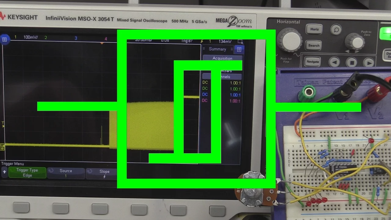
So this is the triangle wave out of the integrator, and this is the square wave out of the comparator. And then, we looked at the output itself of the comparator, which is right there. And when we lose it, it oscillates!
Which we thought was strange. There you go. So it's doing it halfway.
And then Eric, the master of all magic, tried the magic finger. That didn't work, but then you tried... [Eric] We can try the magic finger again. [Marc] Well it made it worse! You have an un-magic finger! [Eric] Yeah I should go and check on it. [laughter] [Marc] But go fix it with magic air. [Eric] So if you take a can of compressed air, and you flip it upside down, like they tell you not to, you can use it like a freeze spray to make things cold. [Marc] And he's going to spray it on this comparator.
And it's fixed! [Eric] Look at that, it works now! [Marc] So, and actually the comparator runs hot. So I think the comparator is toast. Right now it's completely frozen, right, it's this guy over there. [Eric] Very frosty. [Marc] Very frosty. It works, and eventually it will warm up and it will not work anymore. All right, uh, so now I have to look if I have an old comparator.
I do! I have some old ones that were used in core memory! [Ken] The drugs are kicking in. [laughter] [Marc] It's not looking good!
So we were looking at trying to find a replacement for the 710. But it turns out, I have one! It's disguised as a Fairchild part number. But these comparators were developed originally for core memory. They were the earliest analog ICs! So it's a sense amplifier, so this is a 710!
I used it in my core memory videos to make sense amplifiers. So that's what that is. We'll replace it with that. Okay, new comparator in. It looks very similar actually, it has even this little spike at the end. And then, if I increase the frequency... Oh man, it does... It's the same!
That's incredible, it's exactly the same!
[Eric] Oh look at that! [Marc] It's exactly the same! [Eric] Did you already try the cool-down trick? [Marc] No I haven't. I suppose it'll do the same thing.
That's less sensitive, this one.
You've to get it at exactly the right temperature.
[Eric] Now it's just cooling off.
[Marc] So that’s not it. We were led astray by the temp experiment. It would only make things slightly better until we bumped the frequency slightly higher, and then it would be just the same. The fault was elsewhere, and quite elusive.
Okay, we have been bothered by this oscillation problem for the whole afternoon. And we couldn't make sense of it. But I think we've found a smoking gun. So we see a oscillation, and we think: "okay something's going too fast, too much gain at high speed". So we try to slow it with capacitors, filtering, whatsoever. Can never get rid of it, it gets worse.
So what happens is, we see that oscillation at the output of the comparator, when it gets to the bottom. The smoking gun is that the capacitor [voltage] decreases, and then it stays down. And it should not! It should continue to go down until the threshold voltage changes. So we kind of looked at the output of the threshold voltage, and it looked correct. So, it's still a little bit noisy, but the capacitor should continue to discharge.
Let’s freeze on this for a moment. We had seen in the previous episode that in this integrator arrangement, the square wave at the input, in green, controls the triangle wave at the output, in yellow. But it does not! But that cannot be in a circuit that is that simple!
The output must be the integral of the input! Which led us to the answer: maybe our green curve was not controlling the integrator as directly as we had assumed.
And we couldn't understand that, until we looked at the schematic.
And my green trace, that controls the threshold, is from here.
And that's the one that says whether a capacitor is going to go up or going to go down. But the way they control it, there are two paths: there is one pass that goes and charges and discharges the capacitor, and there's another path that controls the threshold of the comparator. And if those are not changing at the same time, the circuit is not going to work! We had assumed they were the same thing! So now we looked at the two path - and remember I changed the transistor in that path.
And that's the one that's controlling the capacitor: charging, discharging.
And then the comparator goes down to zero. But my new transistor is too slow! It doesn't go up!
This fault is utterly devious. I’ll need to explain this with a bit of elevator music. So our circuit is based on a simple analog integrator.
We put a square wave at the input and we get a triangle wave at the output If we want to make it faster, you’d think we could just make the driving square wave faster.
But there is a problem with that.
Since we give less time for the capacitor to charge, the amplitude will be lower.
So that’s not what we do.
Instead we control the charing rate of the capacitor with a variable resistor.
We keep the amplitude constant by checking the triangle output with a comparator.
This is what our 710 comparator does.
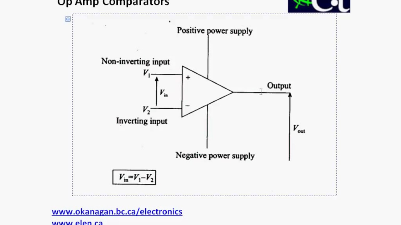
The comparator will switch the integration direction when it hits either rail. But wait a second! We have two levels to compare to, but were very cheap and used only one comparator.
So we use a trick. We feed back the output of the comparator to its reference input. This will generate the two reference levels we need, comparing against a high voltage when charging up, and a low voltage when charging down. Very clever!
But our excessive cleverness is about to bite us in the butt. In the circuit, the comparator connections are not direct. Each of the branches go through a separate buffer, implemented by a bunch of transistors. And I probably made the reference level one slightly slower than the other, with my replacement transistor.
So let’s see what happens now.
This is the part where the triangle wave is going up.
The output soon hits the high comparison point.
The comparator toggles as expected, and both branches switch to low.
Now the triangle wave is going down., and so far, everything is going according to plan.
Eventually we hit the low comparison point. And that’s where things go awry.
The comparator toggles again. But while the integrator driving buffer goes up, the reference level lags behind by a little bit. It stays low for a very short instant.
So now, the triangle rises again, but since the comparison voltage has not switched yet, it immediately crosses it again.
The comparator goes low again.
The triangle wave goes down. And crosses the low level immediately, again!
And the cycle repeats. The reference level buffer never has enough time to catch up.
So we get a fast oscillation. This is extremely unusual. Audio frequency circuits should not be so sensitive to which transistors you use.
And my replacement one is no slouch by any means, it has a transition frequency of 250 MHz, matching the original. But this circuit is incredibly sensitive to variations in the transistor turn-off time. If the two buffers do not switch at exactly the same speed, it becomes unstable.
So it turns out, the the little transistor that I replaced is a vintage speed demon.
It's 18 nanosecond turn off time. And the one I replaced it with was listed as the same frequency transition, 250 megahertz, but the turn off time was much longer.
So I stole this one, put it here, and I put my new transistor over here.
And it doesn't matter, as long as the transition in threshold happens before the reversal of the charging of the capacitor, it should work.
So what I did is that, I took the 2N5134 that was over here, and replaced it over there. And put my slightly slower transistor over there.
So I have now exchanged my two transistors, and the things line up almost the correct way.
You can go from super slow, to really really fast. So, phew, we got it!
Okay so it's still not done, I have to repair the power supply. And I checked all the caps.
Capacitors from 1979!
Is it still good or does it need to be changed? Electrolytics! Change all your electrolytics!
ESR: 216 milli-Ohms.
Capacitance: 4.68 millifarads. And that's supposed to be 4.3 millifarads.
How is that for you? No chinese-made capacitors! Oh, wait, maybe they are! No, no no! Oh oh! From Garden Grove, California! Good stuff from 50 years ago, still good today!
Four millifarads after 40 years, they are still perfect.
So, fortunately it gives us auditory feedback. If I turn it on, it growls.
And I determined that it was this guy that was growling, not this one. And then since that transistor was hot, I just disconnected this, and checked if it worked better. Yes, no growl! So, it's this little power supply that's bad.
Not that many components on it. I'll probably test the diode bridge next.
Okay, diode bridge checks bad. So you check the four diodes in the bridge, and that one is okay, that one is a short! Bad bridge. Okay, I jury rigged a bridge that I had in my bin of good stuff. Let's see if it still growls or not.
One, two - no growl! Okay, at least it passes the audio test.
No se. Nothing.
So after doing a better soldering job... It works better when it's joined with solder! All right, 35 volts, excellent!
Alright, we are starting to see the light at the end of the tunnel. So, I put it back together again, and then, I discovered I had a few more mechanical things to do, as I had not realized that three of the BNC connectors were no longer round and needed to be changed, and one of the banana plugs had been abused too. And for good measure, one of the switches was not behaving either, just one of the two outputs of it.
Fortunately all these remaining issues were minor. The switch was a short circuit from a wire end cut too long, either original, or because it had moved when I replaced the adjacent switch.
The BNCs needed some re-drilling to fit the ones I had on hand. Yes, yes, I had protection on the other side to catch the metal chips and I carefully vacuumed everything afterwards.
The banana plug was the most vexing, as it was bent, and the nut had jumped the plastic threads and mangled them. I eventually managed to take is out, straightened it up, rethreaded the end with its own nut, and all was well.
And the last step is to do the adjustments. There are a million.
And that's for the frequency accuracy.
So here it should be at 100 Hertz. I am at... Pretty close, 107. There you go, 100 Hz.
That should be 1 Hertz, it's 0.997.
10 Hertz and it's 10.05.
100 Hertz and it's 100.09.
One kilohertz and it's 995.1 Etc, etc, you get the idea. It’s not an HP instrument, but it was much more accurate than I expected.
So in the end, what did we have to take out of this machine to exorcise it? Well, quite a bit of things. A lot of broken connectors, broken switches, broken screws, a bad diode bridge, some broken BNCs, and a whole bunch of transistors.
Actually we changed seven of them. Granted, some are because I changed a differential pair, and one is my own doing. But still, that's a lot of bad things in just one unit!
I think I've done it, I've finished my monster breadboard system. So now everything works.
I get my square, I get my sine, it goes slower, it goes faster, it's exactly at the frequency it says it should be. I have my little pulses at the bottom, you can vary the amplitude. I can vary the amplitude of that one, the baseline.
I have the power supplies, we can adjust [them]. And even my little switch number 7 works. So everything works! Now we can just have fun and make circuits with it. Whoa, that was hard! Lots and lots of faults in that beautiful breadboard system.
Yeah, a happy ending, again. Our monster Elite 2 breadboard is able to rejoin its family, with our tricked up Digi-Designer and the simple but elegant BB-IV from the same manufacturer.
Hopefully we’ll make a lot of happy breadboard circuits in the next episodes! See you then!
Up Next

64:44
Shaping Light with Deformable Mirrors | MEMS Adaptive Optics
@bostonuniversity
2.1K views•2013-05-08

30:32
Ultrasonic Transducers: Resonant Frequency Measurement and Horn Design
@imajeenyus42
229.9K views•2017-02-22

54:16
Polymer Environmental Degradation: Mechanisms & Stabilization
@iit
1.8K views•2012-07-10

33:39
How a Student's Question Saved a NYC Skyscraper from Collapse
@veritasium
22.8M views•2025-04-26
Related Study Plans & Knowledge Roadmaps
Structured learning paths in Engineering
engineering
Building Acoustic Levitators: Physics & Arduino
01The Physics of Sound and Standing Waves
02Piezoelectric Transducers and H-Bridge Drivers
03Arduino Programming: Generating 40 kHz Signals
+ 2 more learning modules
14h5 modules
Explore Roadmap
engineering
Building Peltier Cloud Chambers: Particle Tracks
01Cosmic Rays & Cloud Chamber Physics
02Thermoelectric Cooling (TEC) Fundamentals
03Custom Liquid-Cooling Loop Design
+ 2 more learning modules
18h5 modules
Explore Roadmap
engineering
Yagi-Uda Antennas: Modeling, Build & VNA Test
01Introduction to RF and Antenna Fundamentals
02Yagi-Uda Antenna Design Principles
03Antenna Modeling and Simulation in 4NEC2
+ 2 more learning modules
18h5 modules
Explore Roadmap
engineering
ECG Monitor Design: Op-Amps, Filters & Noise
01Electronics & Breadboard Basics
02Op-Amps and Instrumentation Amplifiers
03Bioelectricity and ECG Fundamentals
+ 2 more learning modules
18h5 modules
Explore Roadmap