This video demonstrates the final assembly of a planetary gearbox in SolidWorks, showing how the sun gear, planet gears, carrier, and ring gear work together in mechanical harmony. The tutorial covers the complete assembly process of a 100% modeled planetary gearbox, suitable for basic motor-driven animations and educational purposes.
Planetary Gearbox Final Assembly in SolidWorks: Complete Guide
Added:Deep Dive
Fundamental SolidWorks Assembly Mates: Practical experience with standard mates such as concentric, coincident, and distance to align 3D parts.
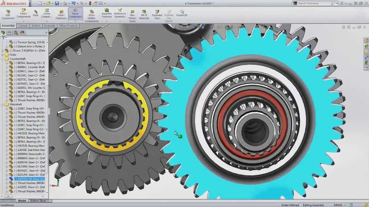
Finally, assemblies done right.
7.6K
SolidWorks assemblies use 'mates' to define how components fit together. The simplest mates include coincident, concentric, and width mates. Smart mates (ALT key during drag) automatically apply appropriate mate types. Components can be reused with automatic mate application. Fasteners from Toolbox snap and resize automatically. The copy with mates command duplicates components with their constraints. When holes are patterned, fasteners populate automatically, updating when hole counts change. Edge selection adds multiple mates simultaneously. Multi-mate groups constraints into single features. The select other tool accesses hidden geometry without rotating the assembly. Width mates solve alignment for asymmetric components like pillow blocks.
Click to watch →
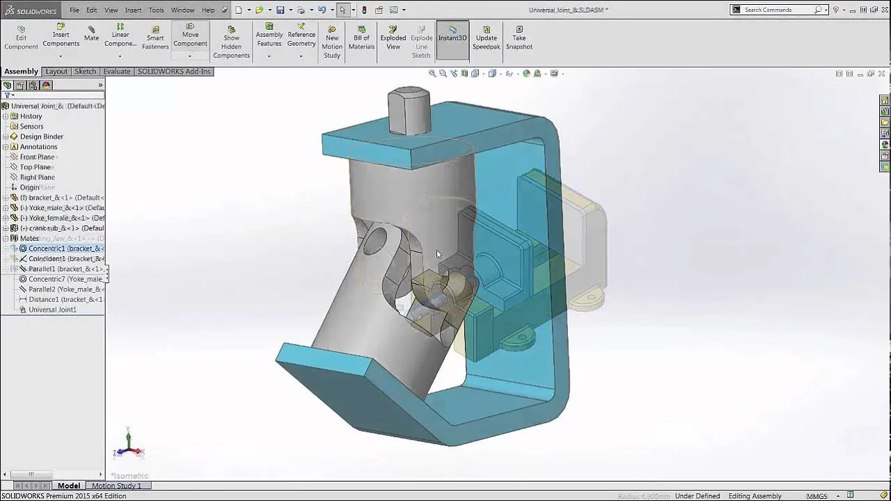
SOLIDWORKS Quick Tip - Introduction to Mates
162.8K
Mates are geometric constraints holding parts together in assemblies, requiring selection of faces, edges, or vertices on separate components. Seven basic mate types exist: Coincident, Parallel, Perpendicular, Tangent, Concentric, Lock, Distance, and Angle. Most mates offer two orientation possibilities, with SolidWorks defaulting to the closest current placement. Advanced mates include Profile Center, Symmetric, Width (centers parts based on four faces with intelligent dimension handling), Path, Linear Coupler, and Limit mates for setting motion boundaries. Mechanical mates simulate complex relationships like cam-follower, peg-in-slot, hinge, gear, rack-and-pinion, screw, and universal joint actions.
Click to watch →
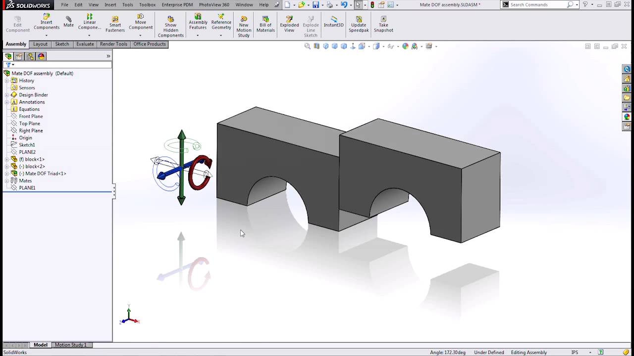
SOLIDWORKS - Assembly Mates and Degrees of Freedom
13.8K
This section covers the foundational concepts of assembly mates in SolidWorks. When components are first added to an assembly, they possess six degrees of freedom: three translational movements along X, Y, and Z axes, and three rotational movements around those same axes. Assembly mates are used to constrain these components by removing degrees of freedom. Different mate types remove different quantities: vertex-to-face removes 1, vertex-to-edge and edge-to-face remove 2 each, face-to-face and vertex-to-vertex remove 3 each, and edge-to-edge removes 4. Understanding these relationships is essential for creating properly constrained assemblies.
Click to watch →
49 Mating parts together in an assembly from the Course SolidWorks 2012 Essential Training
720
Mates are the fundamental skill for working with assemblies in SolidWorks, functioning similarly to sketch relations. The mate window allows selection of entities (faces, planes, lines, points) with standard mate options including coincident, parallel, perpendicular, tangent, concentric, and distance/angle constraints. SolidWorks automatically suggests appropriate mates when selecting pairs. A minimum of two entities must be selected. The mate priority hierarchy is: faces (most robust), edges, then points (least reliable). Concentric mates align circular features, while coincident mates establish face-to-face contact. Parts require a minimum of three mates to be fully defined, with a negative sign indicating degrees of freedom remain.
Click to watch →

Standard Mates | SOLIDWORKS BEGINNER | Chapter 03: Lesson 04 | CSWA COURSE
964
This section covers the foundational concepts of using mates in SolidWorks assemblies. Mates constrain components to act like mechanical systems by creating relationships between parts or between parts and the assembly. Standard mate types include coincident, parallel, perpendicular, tangent, concentric, distance, angle, and lock mates. Proper entity selection is critical—users can select faces, edges, planes, axes, points, vertices, coordinate systems, or arcs. The mate tool is accessed via the Assembly tab or keyboard shortcut 'S'. The Property Manager displays available mate options across four tabs: Standard, Advanced Mates, Mechanical Mates, and Analysis. Understanding these fundamentals enables effective assembly construction.
Click to watch →
Deep Dive
Planetary Gear Train Theory: Understanding the roles and rotational relationships of the sun gear, planet gears, carrier, and ring gear.
FREE CRASH COURSE | Lecture 21 | Concept of Epicyclic Gear Train | Theory of Machines | ME
34K
A planetary gear train (epicyclic gear train) consists of a central sun gear, multiple planet gears that orbit around the sun gear, and a ring gear (annulus) that surrounds the planet gears. The planet gears are mounted on a carrier (arm) that rotates around the sun gear. This configuration allows for multiple gear ratios in a compact space. When analyzing planetary gear trains, you must consider that all planet gears share the same angular velocity (since they are mounted on the same carrier). The analysis involves tracking the motion of the sun gear, planet gears, ring gear, and carrier.
Click to watch →
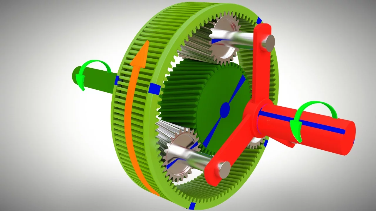
Understanding PLANETARY GEAR set !
11.8M
A planetary gear set, also called an epicyclic gear train, consists of four main components—the sun gear, planet gears, ring gear, and carrier—that work together to achieve speed variation and reverse motion through the fundamental principle that meshed gears must have equal velocity at their interface points; when the ring gear is stationary and the sun gear rotates, the planet gears must both spin and revolve to satisfy velocity conditions, while arresting the carrier produces reverse motion by making the ring gear rotate in the opposite direction to the sun gear.
Click to watch →

05 Theory of Machines Gear Trains Part 1 Dr Ahmed Sameh
22.4K
A planetary gear train consists of a sun gear, planet gears rotating around it, and a carrier holding the planets. To analyze planetary trains, fix the carrier to convert it to a conventional gear train with fixed axes. Apply standard gear ratio formulas: for external meshing n1/n2 = -z2/z1, for internal meshing n1/n2 = +z2/z1. Multiply all speeds by a factor x to account for actual carrier speed. The actual speed of any gear equals the relative speed multiplied by x plus the carrier speed. Solve simultaneous equations using given values (number of teeth, carrier speed, input speed) to find unknown gear speeds and directions.
Click to watch →

Theory of Machine | Gears Train - 3 | Lec 37 | GATE 2021 ME Exam
26.2K
Planetary gear trains (also called epicyclic gear trains) consist of a sun gear, planet gears, and a ring gear, where all gears share the same module for proper meshing. The fundamental formula for calculating gear ratios is ω₁/ω₂ = N₂/N₁, where ω represents angular velocity and N represents number of teeth. For planetary gear trains, the relative velocity method is essential: fix one gear (typically the ring gear), then calculate relative speeds of other gears. The direction convention uses positive signs for clockwise rotation and negative signs for counterclockwise rotation, with external gear meshes reversing direction (negative sign) and internal gear meshes maintaining direction (positive sign). The degrees of freedom for a planetary gear train is calculated as DOF = 3N - 2J - 1, where N is the number of links and J is the number of joints. Planetary gear trains are widely used in automatic transmissions, differentials, and robotics due to their compact design, high torque capacity, and smooth power transmission capabilities.
Click to watch →

Epicyclic Gear Train in Hindi || Planetary Gear Train in Hindi
68.3K
A planetary gear train (epicyclic gear train) consists of three main components: a central sun gear, multiple planet gears that orbit around the sun gear, and an outer ring gear with internal teeth, all mounted on a planet carrier. By locking different components (sun gear, ring gear, or planet carrier) while rotating others, this system can achieve multiple gear ratios including reduction (first gear), overdrive (second gear), reverse, and direct drive, making it highly versatile for applications like automotive transmissions and tank drives.
Click to watch →
Deep Dive
Gear Geometry Concepts: Familiarity with basic gear parameters including module, pitch diameter, pressure angle, and backlash.
Gear Geometry
10.9K
This comprehensive lecture covers the fundamental concepts of gear geometry essential for gear cutting practice. The pitch diameter is a virtual diameter that cannot be physically identified on a gear but is crucial for calculating speed ratios between meshing gears. The law of gearing states that for smooth profiles in contact, if the common normal to the point of contact always cuts the line of centers at a definite point, the speed ratio remains constant. Involute profiles are most commonly used because they maintain constant speed ratio even when center distance changes slightly, which is critical in applications like automobile gearboxes. Key dimension calculations include: pitch diameter = m × Z, outside diameter = m × Z + 2m, root diameter = m × Z - 2.5m, with addendum = m and dedendum = 1.25m. Chordal thickness and chordal addendum are used for measuring gear geometry accuracy with gear vernier toothed calipers.
Click to watch →

This Mesmerizing Gear-Making Process Will Blow Your Mind
73.3K
This section covers the foundational concepts of spur gear geometry. A spur gear has straight teeth parallel to its axis, unlike helical or herringbone gears. Key measurements include: outside diameter (outer edge), pitch diameter (middle reference point), addendum (distance from pitch to outside), and dedendum (distance from pitch to root). The whole depth equals addendum plus dedendum. A rack represents a flat gear with no visible addendum or dedendum. Understanding these relationships is essential for gear design and manufacturing.
Click to watch →
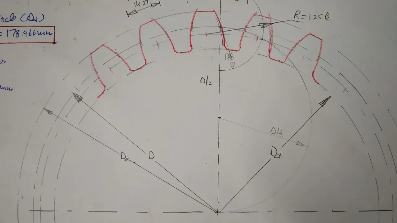
Gear profile by using Approximate method in Mechanical engineering drawing
6.7K
This section covers the essential terminology and principles of spur gear geometry. Three fundamental circles form the basis: addendum circle (outermost, passes through tooth tops), dedendum circle (innermost, passes through tooth bottoms), and pitch circle (theoretical contact point). Key measurements include clearance (distance between dedendum of one gear and addendum of another) and working depth (distance between addendum and dedendum circles). Circular pitch represents the distance between adjacent tooth starting points along the pitch circle, while tooth thickness is the width of each tooth. These parameters define gear proportions and ensure proper meshing between mating gears.
Click to watch →

Построение эвольвентного зацепления
31.1K
This section covers the foundational concepts of gear geometry including divisor circles (marked with dashed lines) and base circles (marked with solid lines). The divisor circles must intersect at the pole point P. The line of action is constructed by drawing a vertical line through the pole and then drawing a tangent to both base circles, forming a 20-degree pressure angle. Points are found where the line of action intersects the base circles, and these points are connected to the respective centers to establish reference geometry for tooth construction.
Click to watch →

Pitch Circle diameter | gear pitch Circle diameter | How to find pitch Circle diameter of gear
49.1K
This comprehensive section covers the core concepts of gear geometry including pitch circle diameter, module, addendum, and dedendum. The pitch circle diameter represents the diameter of an imaginary circle passing through the pitch point where mating gears theoretically roll without slipping. The module (m) is defined as the ratio of pitch circle diameter to number of teeth, representing the size of the gear tooth. Addendum equals the module and represents the height above the pitch circle, while dedendum equals approximately 1.157 times the module and represents the depth below the pitch circle. These relationships form the mathematical foundation for all gear calculations and enable engineers to determine gear parameters when designing or analyzing mechanical systems.
Click to watch →
Deep Dive
SolidWorks Interface and Navigation: Basic proficiency in importing components and organizing the FeatureManager design tree in an assembly environment.

Solidwork Interface|| How to manage file|| Introduction|| 02|| For beginner to advanced
127
SolidWorks is a 3D CAD software for creating 3D models, assemblies, and performing engineering analysis. The interface consists of the title bar, menu bar, and ribbon with organized toolbars. The three basic modules are Part (creating 3D components), Assembly (combining parts with mates), and Drawing (creating 2D production drawings). Navigation tools include the Feature Tree for hierarchical model structure, View Cube for quick orientation changes, and multiple display modes like Shaded with Edges, Shaded, Hidden Lines Removed, and Wireframe. File operations include opening files through the Open option, Recent Folder, or keyboard shortcuts like Ctrl+O. File types include Part (.SLDPRT), Assembly (.SLDASM), and Drawing (.SLDDRW).
Click to watch →
SolidWorks Grundlagen - Teil 1
90.5K
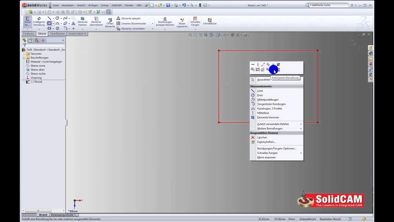
SolidWorks follows the standard Windows interface with pull-down menus at the top providing access to all commands. Toolbars can be managed through three methods: Extras > Anpassen, right-clicking on any toolbar area, or Ansicht > Symbolleisten. Toolbars can be positioned anywhere in the workspace. The Befehlsmanager reduces toolbar clutter by allowing users to add/remove buttons. Under Extras > Optionen, Systemoptionen apply globally across all documents, while Dokumenteigenschaften only affect the current file and include settings like units and material properties.
Click to watch →

Ultimate Solidworks Tutorial for Beginners | solidworks design | सॉलिडवर्क्स ट्यूटोरियल इन हिंदी.
497
SolidWorks is a 3D CAD software for designing parts and products, widely used in companies. The interface consists of an upper ribbon menu with tabs (File, Edit, View, Insert, Tools, Simulation, Window) and a lower workspace. The Home tab shows recent documents, folders, and resources. The File menu provides New, Open, Save, Save As, Print, and Exit options. The Edit menu offers Cut, Copy, Paste, Delete, Undo, and Redo functions. The View menu controls display modes like Wireframe, Hidden Line Visible, Shaded, and Perspective View. The Insert menu provides tools for adding sketch, extrude, revolve, and cut features. The Tools menu includes advanced applications like CAM, Visualize, and Flow Simulation. The Window menu manages multiple documents and views.
Click to watch →

SOLIDWORKS BASIC 솔리드웍스 베이직 2020-2022 (2강) 솔리드웍스의 평면과 스케치도구 (1)
12.8K
SOLIDWORKS interface consists of three main components: the central workspace, Design Tree on the left, and Design Library on the right. The interface resembles Microsoft Office applications. Left mouse button handles selection, right mouse button accesses popup menus. Three default planes (Front, Top, Right) can be displayed simultaneously by dragging to select all. View orientation shortcuts include Ctrl+1 (Front), Ctrl+2 (Back), Ctrl+3 (Left), Ctrl+4 (Right), Ctrl+5 (Top), Ctrl+6 (Bottom). Mouse wheel controls zoom. The coordinate system at the bottom indicates current view orientation.
Click to watch →

Curso Tutorial SolidWorks leccion 1.2 interface de usuario e intencion de diseño
23.4K
The SolidWorks interface consists of the graphical area for displaying pieces, the operation tree showing piece type, material, planes, origin, and operations, and the timeline bar for reviewing creation steps. The top toolbar contains tools for generating solid pieces and surfaces, which can be customized by hiding unused tools. The File menu provides document operations, while the Insert menu contains productivity tools including sustainability analysis and Simulation Express. The Window menu manages multiple open files in various arrangements.
Click to watch →
Prerequisite Knowledge
- Concept 01Fundamental SolidWorks Assembly Mates: Practical experience with standard mates such as concentric, coincident, and distance to align 3D parts.
- Concept 02Planetary Gear Train Theory: Understanding the roles and rotational relationships of the sun gear, planet gears, carrier, and ring gear.
- Concept 03Gear Geometry Concepts: Familiarity with basic gear parameters including module, pitch diameter, pressure angle, and backlash.
- Concept 04SolidWorks Interface and Navigation: Basic proficiency in importing components and organizing the FeatureManager design tree in an assembly environment.
Subsequent Learning
- Step 01SolidWorks Motion Analysis: Simulating dynamic gear rotation, applying motor inputs, and analyzing angular velocity and torque transmission.
- Step 02Finite Element Analysis (FEA) on Gear Teeth: Evaluating stress concentration and tooth deflection under load using SolidWorks Simulation.
- Step 03GD&T and Tolerance Stack-Up: Applying Geometric Dimensioning and Tolerancing to ensure correct backlash and fit during physical manufacturing.
- Step 04Multi-Stage Gearbox Design: Designing and assembly of compound planetary gear systems for higher gear reduction ratios.
- Step 05Manufacturing and Material Selection: Exploring gear manufacturing processes (e.g., hobbing, 3D printing) and selecting appropriate materials for wear resistance.
Symbolic Heat
Vocal Escalation
Rhythmic Calls
Audible Shifts
Final Surge
Symbolic Heat
2:07Playing Section
- 1
Repeated 'heat' chants establish an intense, abstract atmosphere.
- 2
Focus remains on rhythmic vocalization and musical tension.
- 3
No narrative content or explicit thematic development present.
The Limitations of Idealized CAD Assembly vs. Physical Manufacturing Reality
While learning planetary gearbox assembly in SolidWorks is valuable for mastering CAD software, relying solely on idealized digital models can create a false sense of design success. In SolidWorks, gears mesh perfectly using mathematical relations (gear mates). However, this idealized environment completely ignores critical physical realities essential to real-world mechanical engineering, such as gear backlash, tolerance stack-up, thermal expansion, and lubrication. Without incorporating Design for Manufacturing (DFM) principles, a perfectly aligned CAD assembly may result in a physical prototype that jams, wears out rapidly, or cannot be assembled due to manufacturing variances. To truly understand planetary gearbox design, students must look beyond perfect CAD mates and study tolerance analysis, physical material properties, and manufacturing constraints.
Deep Dive
SolidWorks Motion Analysis: Simulating dynamic gear rotation, applying motor inputs, and analyzing angular velocity and torque transmission.
SOLIDWORKS Motion - Introduction
148.9K
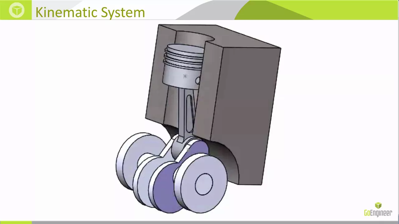
SolidWorks offers three motion analysis types: animation (purely visual), basic motion (limited physics), and motion analysis (full rigid body dynamics with ADAMS solver). Motion analysis requires assemblies with fixed components and examines relative movements. Every rigid body has six degrees of freedom (three translational, three rotational) unless restrained by mates. Setting up a kinematic motion study involves enabling SolidWorks Motion, creating a new study, configuring mates (hinge, concentric), applying gravity, and defining motors. Motors drive components at specified rates regardless of external loads. Post-processing reveals torque requirements and displacement measurements. Initial positions critically affect results, and mate modifications create new keyframes at current timeline positions.
Click to watch →

Инструмент для анализа движения SolidWorks Motion
45.1K
SolidWorks Motion provides four levels of motion analysis tools: Animation for creating visual animations, Basic Motion for simple movement simulation with motors and contacts, Motion Analysis for calculating forces, power, and displacement, and Event Motion for simulating complex processes with events and sensors. The tools enable engineers to analyze moving mechanisms by adding components like motors, gravity, contacts, and forces, then calculating results such as power consumption, reaction forces, and displacement to validate designs before physical prototyping.
Click to watch →
Solidworks tutorial | sketch Computer fan in Solidworks
178.4K
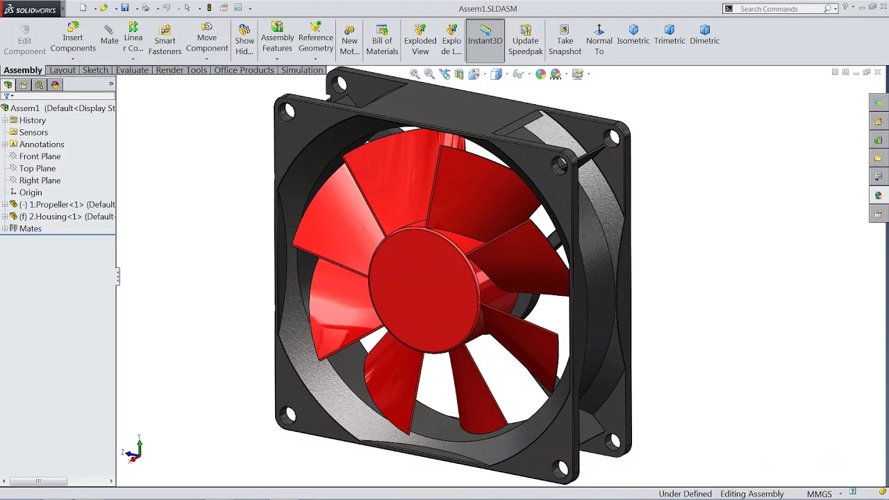
This extensive section demonstrates advanced SolidWorks techniques for completing mechanical component design and performing motion analysis. The workflow includes creating cable passages with exact dimensional tolerances using extruded cuts and colinear relations, trimming excess geometry with trim entity operations, and creating internal passages by extruding cuts through all material layers. Corner rectangles form stable base structures that attach to adjacent components. Material selection from libraries provides realistic visual rendering. The section transitions to assembly creation, where individual parts are combined using mates to constrain components together. Motion analysis is performed by accessing the motion manager and creating a motion study, adding motors to simulate rotation at specified RPM, and generating exploded view animations using the animation wizard. Finally, motion studies are exported as AVI video files with configurable settings including resolution and frame rate. This comprehensive demonstration covers the complete workflow from individual component creation to integrated system simulation and visualization.
Click to watch →

ภาพรวมการใช้งาน SolidWorks Motion Analysis
75.4K
SolidWorks Motion Analysis is an add-in function that enables simulation of mechanical systems with moving parts, allowing users to analyze motor requirements including power, torque, and speed specifications through features like contact settings, material properties, and gravity configuration, with results displayed through graphs showing displacement, velocity, acceleration, and force data.
Click to watch →

Mecanismo biela - manivela - corredera | Análisis cinemático | SolidWorks
92K
This segment explains the complete workflow for configuring kinematic analysis in SolidWorks Motion. After adjusting the crankshaft length to 60mm for proper mechanism operation, the analysis environment is accessed through the Study tab. SolidWorks Motion is activated via Add-ins if not already enabled, revealing additional analysis options. The motor setup involves selecting the crankshaft's cylindrical face, setting angular velocity to 20 RPM, and reversing rotation direction as needed. Analysis duration is configured by adjusting the timeline slider. Results categories include displacements, velocities, accelerations, forces, and moments. For detailed analysis, local coordinate systems are established for components, and graph settings allow unit conversion (mm/s to m/s) and title customization. This systematic configuration process enables engineers to simulate and analyze the dynamic behavior of mechanical systems before physical prototyping.
Click to watch →
Deep Dive
Finite Element Analysis (FEA) on Gear Teeth: Evaluating stress concentration and tooth deflection under load using SolidWorks Simulation.

Lab 4. Gear Tooth. Lecture 23.
534
This lecture demonstrates a finite element analysis of a gear tooth using two 20-node hexahedral elements, comparing aligned and misaligned loading conditions. The aligned case shows modest von Mises stresses around 142 MPa, while the misaligned case produces significantly higher stresses of approximately 563 MPa (more than three times the aligned case). The analysis uses three commercial FEA codes (MSC Nastran, Mark, and Asteros) to validate results, showing good correlation in displacement predictions but variations in stress values due to different averaging methods. The key insight is that eccentric loading creates a concentrated stress singularity at the load application point, which is an academic exercise rather than a practical engineering solution.
Click to watch →
FEM Case study 1: Investigating how a gear will fail under high forces with SolidWorks Simulation
28.2K
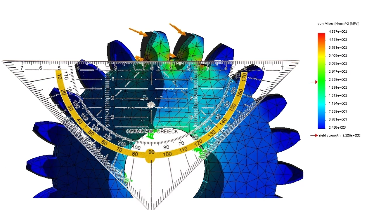
Finite Element Analysis (FEA) using SolidWorks Simulation can predict gear tooth failure by identifying high tensile stress at the base of teeth; the first principal stress vector plot reveals that maximum shear stress occurs at a 45° angle relative to tensile stress, causing teeth to shear off at their base when the von Mises stress exceeds the material's yield strength.
Click to watch →
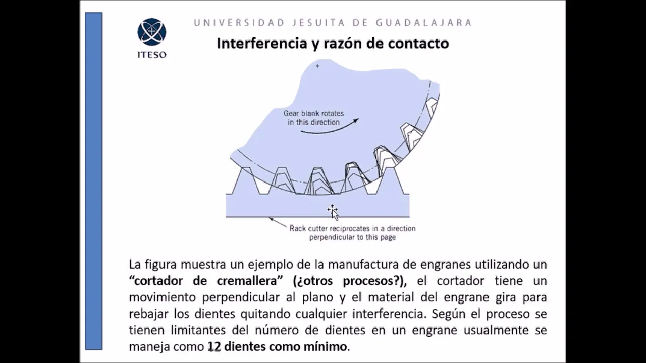
Engranes: interferencia, fuerzas y resistencia
2.7K
Setting up gear FEA in SolidWorks involves: (1) Creating an assembly with two gears at correct center distance; (2) Fixing one gear and allowing the other to rotate; (3) Applying materials to both gears; (4) Defining connections with no penetration; (5) Applying torque to the driving gear; (6) Generating mesh (finer mesh in contact zones); (7) Running the static study. The analysis shows stress concentrations at tooth roots and contact points.
Click to watch →

FEM in 2020 New Graphic Selections
1.7K
This segment covers the complete workflow for performing finite element method (FEM) stress analysis on gears using KISOFT's integrated approach. The process involves defining analysis parameters including boundary conditions, mesh density, stress criteria (von Mises or maximum principal stress), and analysis type (2D plane stress or 3D). Engineers must specify the input load point at the high point of single tooth contact. The automated system generates meshes and applies loads in the background, completing analysis in approximately one minute. Results are compared against industry standards such as AGMA or ISO, with critical points identified using a 30-degree tangent line on the tooth profile.
Click to watch →
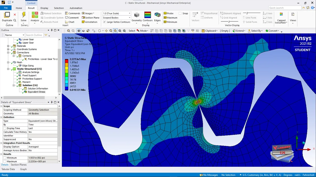
Spur Gear Simulation (Ansys Workbench)
17.1K
This tutorial demonstrates how to perform a finite element analysis of meshing spur gears in ANSYS Workbench, showing that maximum stress occurs at the tooth root due to bending and at the contact surface due to compression when transmitting torque; the simulation process involves importing geometry, converting from 3D to 2D analysis, defining material properties (structural steel, 1-inch thickness), setting up frictional contact between gears, applying boundary conditions (fix support on lower gear rim, frictionless support on upper gear rim), and applying a 15,000 lb-in moment load to assess equivalent stress distribution.
Click to watch →
Deep Dive
GD&T and Tolerance Stack-Up: Applying Geometric Dimensioning and Tolerancing to ensure correct backlash and fit during physical manufacturing.
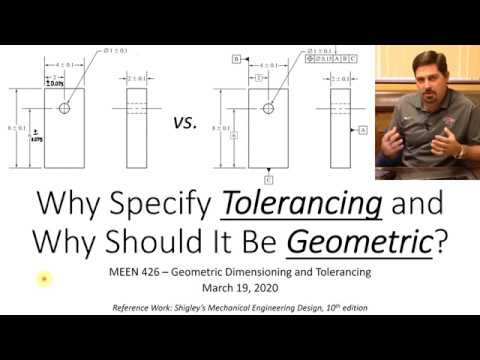
Geometric Dimensioning & Tolerancing vs. Traditional | 4 Fundamentals of GD&T | Ideas & Terminology
98.5K
Tolerance stack-up occurs when tolerances on multiple dimensions combine to create larger overall variation. For example, three dimensions each with ±1 unit tolerance can result in ±3 unit tolerance for derived dimensions. Baseline dimensioning reduces maximum possible error by measuring all dimensions from a common reference point. This approach typically limits worst-case tolerance to ±2 units instead of ±3, providing better control over critical dimensions like hole spacing that require high precision.
Click to watch →

What is Tolerance stackup Analysis-Fundamentals-GD&T
53.6K
Tolerance stackup analysis is a numerical method used to determine whether components in an assembly will interfere with each other by calculating the cumulative effect of individual tolerances across multiple parts, considering factors like material properties, machining processes, machine accuracy, and environmental variables to verify if surfaces will touch, if parts will fit within grooves, and if assembly conditions will be satisfied.
Click to watch →

GD&T Lesson 1: Four Key Concepts
229.6K
This video lesson introduces four fundamental concepts of Geometric Dimensioning and Tolerancing (GD&T): (1) Datums are theoretical reference points, lines, or planes used to establish measurement origins for locating and orienting features on a part; (2) Feature Control Frames are standardized box notations that replace descriptive notes, containing geometric characteristic symbols, tolerance values, and datum references to reduce interpretation ambiguity; (3) Material Condition Modifiers (MMC, LMC, RFS) control how geometric tolerances relate to part size, with MMC allowing more tolerance as features depart from maximum material condition and LMC doing the opposite; (4) Basic Dimensions are theoretically exact values associated with feature control frames that show where tolerance zones should be located, and unlike plus/minus dimensions, they don't contribute to tolerance stack-up calculations.
Click to watch →

Tolerance Stackup: Simple Assembly
92.8K
Tolerance stack-up is a systematic method for calculating cumulative variation in an assembly by following each dimension from one side of a gap to the other. The process involves: (1) selecting a starting point on one side of the gap, (2) tracing through all connected dimensions to reach the opposite side, (3) assigning positive values to dimensions going in one direction and negative values to those going in the opposite direction, and (4) summing all dimensions to get zero (since they form a closed loop) while adding all tolerances together to determine total variation. This method ensures that all dimensions are properly accounted for in the assembly analysis.
Click to watch →

Calculating Position Tolerance Values With Fixed Fastener Formula
23.3K
Geometric Dimensioning and Tolerancing (GD&T) is fundamentally designed for assemblies rather than individual detail parts. The true value of GD&T becomes apparent when performing tolerance stack-ups and analyzing how tolerances interact at the assembly level. In the micrometer holder assembly, the two threaded holes serve as the primary datum features because they are the functional mating surfaces. All other dimensions derive from these holes, minimizing tolerance stack-up since the mating surfaces align directly between parts. This approach ensures that the critical functional relationships are maintained while allowing flexibility in non-critical dimensions.
Click to watch →
Deep Dive
Multi-Stage Gearbox Design: Designing and assembly of compound planetary gear systems for higher gear reduction ratios.

محاسبات و طراحی چرخ دنده - قسمت نهم (Gear Design)
193
Triple reduction gearboxes are used in multi-stage systems where speed is reduced and torque increased across three stages. The software's triple reduction tool allows specifying overall ratio (e.g., 80:1) and calculates tooth combinations for each stage. For example, 12, 52, 14, 60, 13, and 56 teeth achieve the 80:1 ratio through multiplying individual stage ratios. The software optimizes for weight, volume, or other criteria. Minimum and maximum tooth counts can be set (e.g., 17-25 teeth). The software may not achieve exact ratios, showing small delta errors that can be acceptable. The design can be extended to 9-10 stages for very high reduction ratios.
Click to watch →
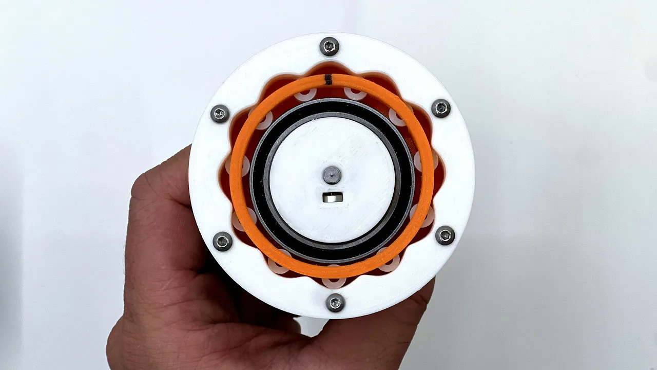
Wave Drive with Rolling Elements — Cycloidal Gear Alternative!
96.1K
A second stage can be added to increase overall reduction ratio. Starting with an 8:1 reduction ratio, adding a second stage transforms it into a powerful 64:1 reduction ratio while maintaining compact size. This demonstrates how cascading stages can achieve high reduction ratios within limited space, making multi-stage designs valuable for applications requiring extreme speed reduction.
Click to watch →
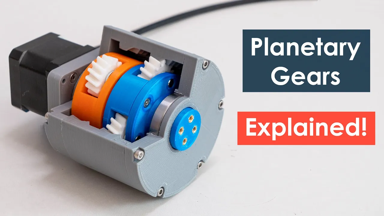
How Planetary Gears Work | 3D Printed Planetary Gearbox Design and Test
737.2K
To achieve very high reduction ratios, planetary gearboxes can be designed as multi-stage systems where two or more planetary gear sets are connected in series. The output of the first planetary gear set becomes the input of the second planetary gear set. The final ratio of the gearbox is the product of the two gear sets' ratios. A single stage planetary gearbox can typically provide ratios as low as 3:1 or as high as 10:1, so multiple stages enable achieving very high reduction ratios like 15:1 or higher.
Click to watch →
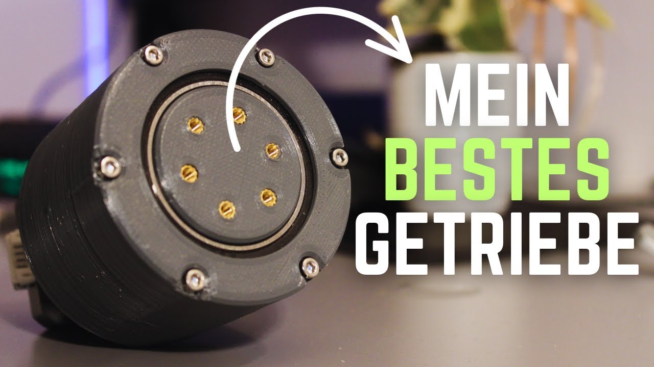
MEIN bisher BESTES Getriebe! | 3D-gedrucktes Planetengetriebe
18.9K
Multi-stage planetary gearboxes achieve higher ratios by connecting multiple stages in series. The demonstrated design uses two stages with 4:1 ratio per stage, achieving 16:1 total ratio. Key design improvements include reducing planet gears from four to three to prevent structural weakness, using helical gears instead of spur gears for reduced vibration and better force distribution, and adding a sun gear on the planet carrier for the second stage. Efficiency testing showed 84.38% for the second version. The design trade-off between backlash and efficiency remains critical: reducing backlash increases friction and reduces efficiency. Position monitoring sensors should be mounted at the gearbox output rather than the motor to measure backlash accurately.
Click to watch →
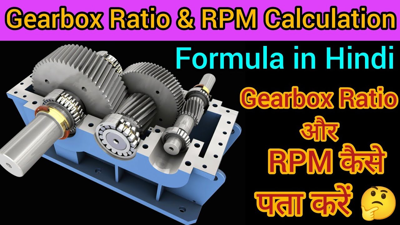
Gear Box Ratio and RPM Calculation formula in Hindi | Gearbox Ratio Calculation formula | #gearbox
7.3K
This section covers the foundational concepts of multi-stage gearboxes. The instructor explains key terminology: the 'driving gear' (connected to the motor) initiates motion transfer, while the 'driven gear' receives motion. To calculate ratios, one must count gear teeth (demonstrated with 15T, 20T, and 45T gears). Gearboxes are classified by stages: single stage (one gear pair), double stage (two gear pairs), and triple stage (three gear pairs). The instructor emphasizes that without knowing tooth counts, ratio and RPM calculations are impossible. This foundational knowledge enables understanding of how gearboxes reduce motor RPM to suitable levels for driven equipment.
Click to watch →
Deep Dive
Manufacturing and Material Selection: Exploring gear manufacturing processes (e.g., hobbing, 3D printing) and selecting appropriate materials for wear resistance.

How Mechanical Engineers Select the Right Material
11.6K
Material selection is inseparable from manufacturing processes. Machining applies to metals and engineering plastics for high precision and moderate volumes. Injection molding uses thermoplastics with high tooling costs but low per-part costs for high volumes. Die casting employs non-ferrous alloys for complex thin-walled metal parts. Forming/stamping relies on ductile metals with high work hardening exponents. Additive manufacturing enables geometry-first designs with internal features impossible to machine or cast. Each process imposes material compatibility requirements that must be considered alongside performance criteria.
Click to watch →

BMMP2543 Materials Selection Course Week 1
240
Materials selection is a systematic decision-making process for choosing appropriate materials for products, not simply selecting the cheapest option. Engineering materials include metals/alloys, polymers, elastomers, glasses, ceramics, and composites. Selection criteria encompass shape considerations, cost competitiveness, machinability, environmental impact, and mechanical performance. The relationship between function, process, shape, and materials is fundamental: mechanical design begins with functional needs, processes are limited by material capabilities, and function/process/shape dictate material attributes. Manufacturing processes are categorized into primary shaping (transforming raw materials into initial forms), secondary shaping (refining into final products), joining (assembling parts), and surface treatment (modifying for specific attributes). Product shapes include prismatic, sheet, and 3D categories.
Click to watch →

P3 Prosman DJ
304
Material selection is a critical step in manufacturing, as errors in material choice can have fatal consequences. Materials are broadly categorized into metals and non-metals. Metals include ferrous metals (iron, steel) and non-ferrous metals (copper, aluminum, zinc). Non-metals include ceramics, wood, plastics, rubber, and composites. Materials are characterized by physical properties (color, density, thermal conductivity) and mechanical properties (strength, hardness, machinability). The machinability of a material determines whether it can be effectively processed using manufacturing equipment.
Click to watch →

GSRTC Helper Revision Classes | Technical Special | GSRTC Helper Exam Paper #15 | Lakshyam Academy
7.6K
Material selection is fundamental to manufacturing, where specific materials are chosen based on component function and operating conditions. Pistons use aluminum alloys for low weight and thermal conductivity. Crankshafts require forged steel for strength and fatigue resistance. Forging involves heating metal and shaping it with compressive forces between dies. High carbon steel provides hardness for hammer heads and chisels. Tool steel withstands impact loads for center punches. Gray cast iron offers mass and damping for industrial flywheels. Cast iron provides rigidity for micrometer frames. Stainless steel ensures wear resistance for measuring jaws. Understanding material properties enables engineers to select appropriate materials for optimal performance and durability.
Click to watch →

Production Technology I AL 2027 I Ep2
141
Material selection for manufacturing requires understanding production requirements, identifying suitable materials, evaluating material properties, and selecting materials that meet specifications. Manufacturing processes include drop forging (heating metal and striking with a hammer or press), machining (cutting to specifications on a lathe), and bending (heating and shaping in a die). These processes transform raw materials into finished products with specific properties and dimensions.
Click to watch →
Symbolic Heat
Vocal Escalation
Rhythmic Calls
Audible Shifts
Final Surge
Symbolic Heat
2:07- 1
Repeated 'heat' chants establish an intense, abstract atmosphere.
- 2
Focus remains on rhythmic vocalization and musical tension.
- 3
No narrative content or explicit thematic development present.
The Limitations of Idealized CAD Assembly vs. Physical Manufacturing Reality
While learning planetary gearbox assembly in SolidWorks is valuable for mastering CAD software, relying solely on idealized digital models can create a false sense of design success. In SolidWorks, gears mesh perfectly using mathematical relations (gear mates). However, this idealized environment completely ignores critical physical realities essential to real-world mechanical engineering, such as gear backlash, tolerance stack-up, thermal expansion, and lubrication. Without incorporating Design for Manufacturing (DFM) principles, a perfectly aligned CAD assembly may result in a physical prototype that jams, wears out rapidly, or cannot be assembled due to manufacturing variances. To truly understand planetary gearbox design, students must look beyond perfect CAD mates and study tolerance analysis, physical material properties, and manufacturing constraints.
Fundamental SolidWorks Assembly Mates: Practical experience with standard mates such as concentric, coincident, and distance to align 3D parts.
Planetary Gear Train Theory: Understanding the roles and rotational relationships of the sun gear, planet gears, carrier, and ring gear.
Gear Geometry Concepts: Familiarity with basic gear parameters including module, pitch diameter, pressure angle, and backlash.
SolidWorks Interface and Navigation: Basic proficiency in importing components and organizing the FeatureManager design tree in an assembly environment.
SolidWorks Motion Analysis: Simulating dynamic gear rotation, applying motor inputs, and analyzing angular velocity and torque transmission.
Finite Element Analysis (FEA) on Gear Teeth: Evaluating stress concentration and tooth deflection under load using SolidWorks Simulation.
GD&T and Tolerance Stack-Up: Applying Geometric Dimensioning and Tolerancing to ensure correct backlash and fit during physical manufacturing.
Multi-Stage Gearbox Design: Designing and assembly of compound planetary gear systems for higher gear reduction ratios.
Manufacturing and Material Selection: Exploring gear manufacturing processes (e.g., hobbing, 3D printing) and selecting appropriate materials for wear resistance.
901 views30likes10:55@CadelicsOriginal Release: 2025-05-11
[Music] [Music] Heat. Heat.
[Music] [Music] Heat. Heat. Heat.
[Music] [Music] Oh, [Music] [Music] [Music] [Music] [Music] Heat. Heat.
[Music] Heat. Heat.
[Music] [Music] Heat.
Heat.
[Music] Heat.
Heat. Heat. Heat.
[Music] [Music] [Music] [Music] Heat.
[Music] Heat.
[Music] [Music] Heat. Heat.
[Music] Heat.
[Music] Heat.
[Music] Heat.
[Music] Heat. Heat. Heat.
[Music] [Music] Heat.
[Music] Heat. Heat.
[Music] Heat. Heat. Heat.
N. Heat. Heat. N.
[Music] Heat. Heat.
[Music] Brother.
[Music] [Music] Please. Heat. Heat.
[Music] N.
[Music] Heat. Hey, heat. Hey, heat.
[Music] I feel you now.
[Music] You see [Music] is heat.
[Applause] [Music] Heat up here.
[Music] Heat up here.
[Music] [Applause] [Music] [Applause] Heat. Heat.
[Music]
Up Next
7:05
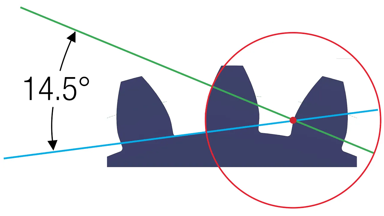
Understanding Gears in Fusion 360: Pressure Angle & Parameters
@AvivMakesRobots
50.4K views•2019-11-12

12:54
Triumph of Orthodoxy Icon: Byzantine Art & History Explained
@BenCallan
2.1K views•2024-08-06

9:49
FastAPI vs Flask vs Django: Choosing the Right Python Web Framework
@TechWithTim
302.5K views•2024-05-26

1:42
Game of Thrones Opening Credits: A Cinematic Analysis
@gameofthrones
46.3M views•2011-04-18
Related Study Plans & Knowledge Roadmaps
Structured learning paths in General & Interdisciplinary Studies
general-studies
Elevator Engineering: History, Physics & Cities
01From Hoists to Safety Brakes: The Dawn of Vertical Lift
02Hydraulic vs. Traction: The Engineering Physics of Elevators
03Modern Speed, Safety, and Algorithms
+ 2 more learning modules
12h5 modules
Explore Roadmap
general-studies
Rubber: Material Science, History & Geopolitics
01Origins of Natural Rubber & Mesoamerican History
02The Chemistry of Natural Rubber & Vulcanization
03The Geopolitics of the Rubber Boom & Colonization
+ 2 more learning modules
12h5 modules
Explore Roadmap
general-studies
Containerization: Evolution, Logistics & Trade
01Ancient Trade & Bulk Cargo: Amphorae to Barrels
02The Industrial Revolution & Cardboard Packaging
03The Containerization Revolution: Malcom McLean
+ 2 more learning modules
12h5 modules
Explore Roadmap
general-studies
Textile Tech: Evolution, Labor & Global Impact
01Pre-Industrial Textiles: Handloom & Cottage Industry
02Mechanization: The Spinning Jenny to the Power Loom
03The Factory System & Global Labor Transformation
+ 2 more learning modules
10h5 modules
Explore Roadmap