



















A 4F correlator is an optical system that uses two lenses separated by four focal lengths to compute the Fourier transform of an image; the first lens creates a diffraction pattern from the input image, the second lens focuses this pattern onto a screen where spatial frequencies are represented as points, allowing optical image processing operations like blurring or correlation matching without digital computation.
How Lenses Compute Fourier Transforms: The 4F Correlator Explained
Added:Fundamentals of wave optics, including wave propagation, interference, and the principles of Fraunhofer diffraction.
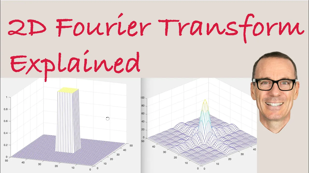
The mathematical concept of the 2D Fourier Transform, specifically how it decomposes signals or images into spatial frequencies.
Basic geometrical optics, including the thin-lens equation, focal length, and the concept of wavefronts.
The concept of spatial frequency in imaging, understanding how fine details correspond to high frequencies and smooth areas correspond to low frequencies.
Practical spatial filtering techniques in the Fourier plane, such as edge enhancement (high-pass filtering) and noise reduction (low-pass filtering).
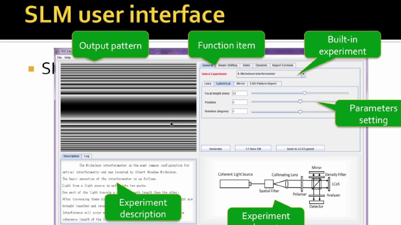
The operation and integration of Spatial Light Modulators (SLMs) to dynamically manipulate phase and amplitude within a 4F correlator system.
Optical computing applications, including Optical Neural Networks (ONNs) that perform convolution operations at the speed of light.
Advanced coherent imaging systems, such as holography, Fourier ptychographic microscopy, and optical pattern recognition via Joint Transform Correlators.
153.6K views3.4Klikes13:32Original Release: 2012-11-12
Hey everyone. Recently, someone at work said that uh plain old lenses actually take the foyer transform of the image that you put into them. So, at first that seems pretty weird. How does a plain old piece of glass like this perform a complex mathematical operation such as a foyer transform? So, I looked into it and let me show you what I found out.
Most engineers are probably more familiar with foyer transforms as they apply to temporal waveforms. So, for example, if you're looking at a sine wave on your oscilloscope, you might use the FFT function to see what it looks like in the frequency domain. Uh, and you'll see for a sine wave, you'll see a nice spike at the fundamental. And for a square wave, you'll see all of the harmonics. And for a real world noisy waveform, you'll see the noise in between all the fundamentals in the and harmonics there. In cases like these, we aren't really looking at phase information. So, this foyer transform is only the magnitude. So if you shifted this wave over a little bit, you'd have the same exact output here because this is not showing us any phase information.
It's just the magnitude of the component uh waves that that are needed to create this.
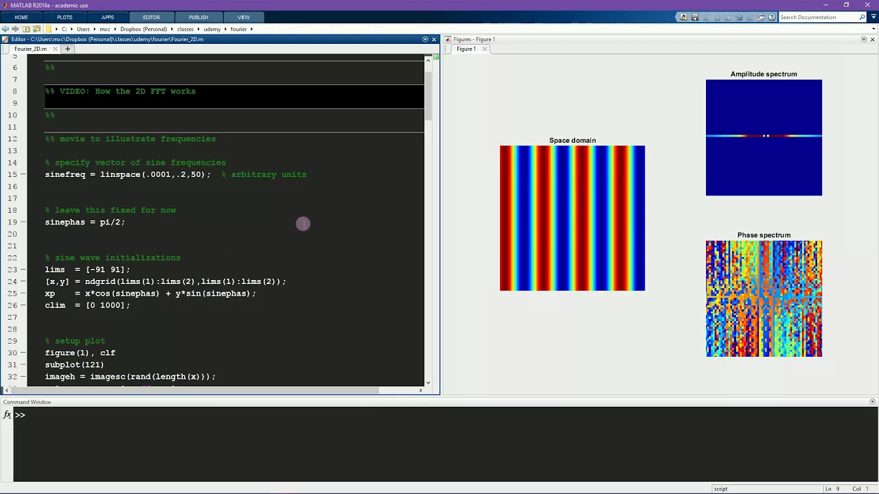
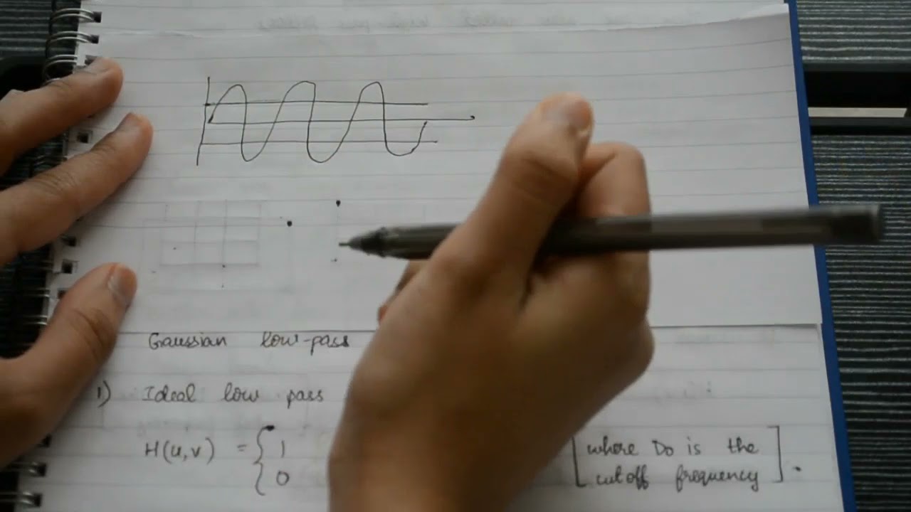
The same concept can be applied to things in the spatial domain. So let's say we had an image that looked like this. It's basically a sine wave of intensity across the x-axis. So every scan line is the same and they all have this sort of um uh intensity pattern. So if we were to it's possible to use the same mathematics to apply a foyer transform to this. So if we do that what you end up with is an output image with uh a dot here and a dot here.
So what's happening is is the x-axis is showing us uh the frequencies just like in the first plot here is showing us a spike where this fundamental frequency lives and it's it's um doubled across the y- ais because that's how the math works out.
There is an excellent tutorial that I'll put a link to in the description that describes this in much more detail and uh does a really good job. So check that out if you're interested in uh image transforming using foyer transforms.
Similarly, if we were to take the foyer transform of this image, we would have uh the fundamental being really bright two little dots there and then a slight decreasing in intensity more and more dots going off the x-axis. And so this is again the same as this that you have decreasing intensities of the harmonics and that creates the square wave. So this works in the other axis too. If we were to rotate this 90° and we had a square wave in the y direction then uh we would just have the pattern in the y direction here. So every point on this two-dimensional plane represents a spatial frequency in the original image.
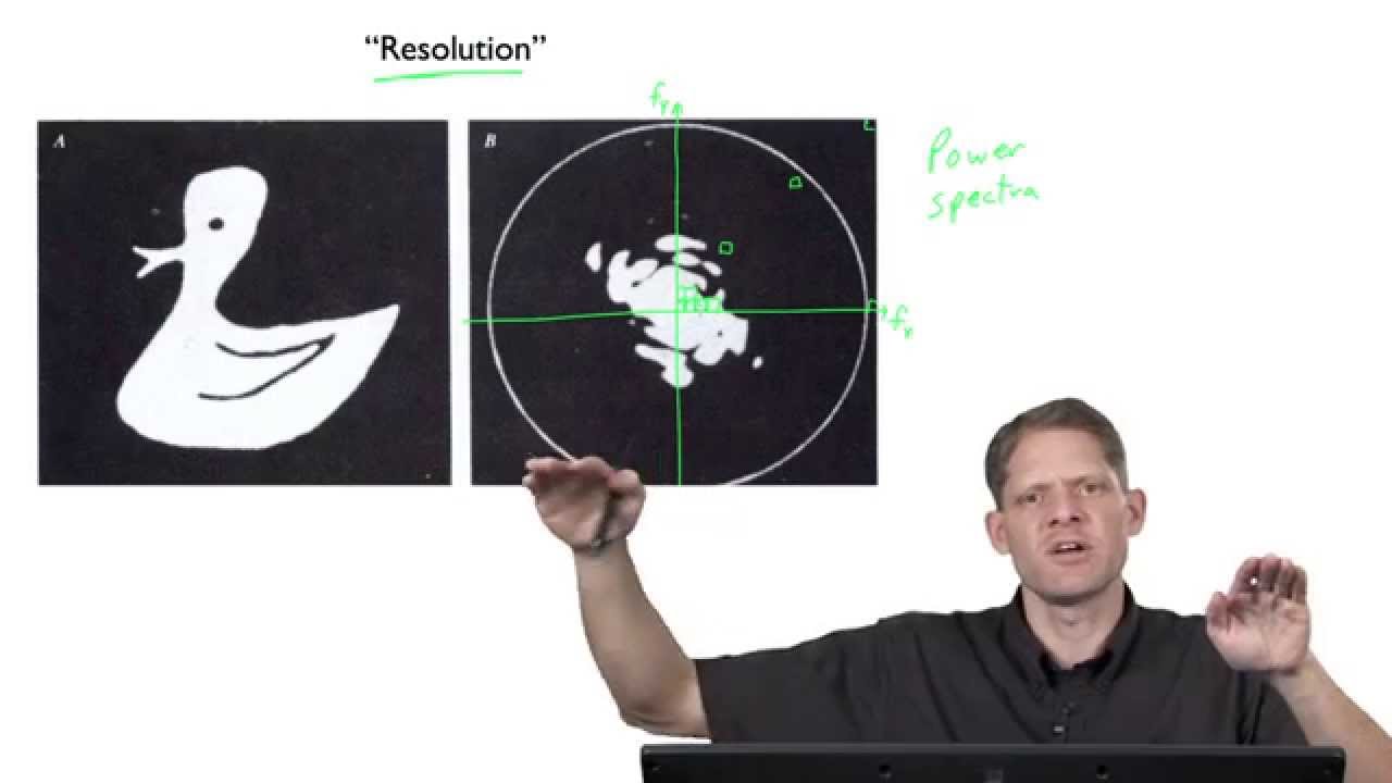
If you take the forier transform of a of a normal looking picture, you know, a picture photograph of a house or whatever, you you'll end up with something that looks like this. There'll be a really really bright spot at the center and then there's just kind of a whole bunch of random looking noise around the outside. And the reason for that is that pictures are very complex spatially. And so if you think about all the frequencies you'd have to add together, all the different spatial frequencies to come up with something that looks like a real photo, uh you'd realize how much information is actually in the uh amplitude plot. And again, this does not include phase information.
Just like talking about over here, uh we're we're only discussing the frequency components. So if you take the fora transform of this image and only look at the magnitude plot, you actually cannot reconstruct the image fully because we only have the frequency information.
One of the interesting side effects of have having only a frequency information in the amplitude plot is that the location of the feature in the image doesn't matter. So definitely check out that tutorial. But basically taking the FFT and looking at only the magnitude, the frequency output. uh an input image looking like this would give exactly the same output as an image looking like this because the feature is the same has the same dimensions but it it's at a different location in the image. So this will become important later.
Okay, so now that we have a basic idea of what a foyer transform is in an image, how in the world does a plain piece of glass actually make it happen?
Uh there's a few important catches that I ran into. So if you're going to try this yourself, um definitely check this out.
If you search around on the internet, you'll you'll quickly run into something called a 4F correlator, which is sort of the quintessential foyer optics device.
And um this does work. I I'll show you later. I actually did get some results out of it, but there's a lot of catches.
So saying, oh well, a lens takes a 4A transform is true, but that you can't really make use of it except in some very limited cases. So one problem is that you get the phase information out as well as the amplitude magn uh information.
So in that tutorial you'll see that the phase images that you get out of a 4A transform are really messy and it makes it such that you can't really extract anything meaningful out of it because um it's just so wild. I mean you can't I mean mathematically you can do things with it but if you just sort of look at it on a screen it doesn't really tell you anything.
So the 4F correlator is set up to only show amplitude information. And it does this by using a laser, which is a coherent light source. So let me show you how it's set up. I used a helium neon laser and then hot glued a microscope objective to the front of it and looked at a screen while I was setting it up just to get it in exactly the right spot. And then you you send the output of that through a pinhole.
Now the idea this is called a spatial filter. Like if you go online and search for this stuff, they'll be talking about spatial filters, but really all that is is just a pinhole and it's situated such that it's at the focal point of the microscope objective. There's a chart that shows the optimum pinhole size for a given microscope objective and input beam. And I which I didn't have. Edmond said I actually had to get down to about 5 or 10 microns, but I didn't have a hole that small. I did have a 30 micron aperture that I used um with my SEM. You can see the effect that the pinhole had.
Without it, there's quite a lot of uh spatial noise in the beam. It's just not very clean. And with the pinhole, uh we have a nice smooth Gaussian distribution out there, which just means that the the beam is bright at the center and has a nice smooth taper out to the edges. So, it's really just an ideal sort of um source of light.
Uh next, this first lens is used just to columnate the beam. So, the light rays are coming in at an angle and are hopefully coming out straight. And I tested this pretty simply just by uh using a pair of calipers and making a couple marks on a projection screen and then setting up the projection screen very far away and then holding the calipers in the beam out here. So, if the projection if there were no optics in here and I had the projection screen way out here and I I put the calipers here and knew that that the distance was the same on the screen as between the caliper uh jaws, I could move this around a bit until it was columnated because we know that if the light is going perfectly straight, the distance between the jaws would be the same as the distance marked on the screen.
This distance is not too important in the system. It's because the light is columnated.
Um, the rest of it is really just two lenses in a projection screen. And and for most of the work that I was doing, I didn't even really need this part cuz you can you can put a screen here, too.
So, what happens is you put your your input image here. This is just a plain old lens. Uh, f is the focal length of the lens. At this plane in space, you're you're supposed to get the forier transform, which you do, but I'll talk about that in a minute. and then another f another focal length there's another lens and then another focal length there's the output screen so this is an image plane this is an image plane and this is the foyer image plane since we're dealing with monochromatic light from the laser you can't really just put a a photograph here unfortunately the image has to be a a a clear thing that just blocks out light where you don't want it and so I I got a a transparency and just printed some stuff on it. I also used this because this is actually quite opaque and it has nice sharp edges on there. This is just a a lid to a a box of optics.
I also tried things like combs like this.
Um I also tried one of the best objects I tried was this very fine copper mesh.
Now, this is sort of cheating because you can actually see the diffraction pattern just looking through this at a light source, but um anyway, I'll talk about some of the resulting images I got in a minute. So, here's how this thing works. If you had nothing in the image plane, let's just say it was a clear shot from this columnating optic into this first optic here. All of the photons are going at 0°, let's just say, all parallel. And every photon that goes into this lens, it should be focused down to exactly the same point.
So if you put a screen here with nothing in the between these two, you'll get one really really sharp bright point right at the center.
Now if we put something in the image plane like let's say a uh a letter A where the light hits the edge of this pattern there will be some defraction and the defraction will cause the light to slightly diverge. So instead of going straight out where the light hits an edge of a feature, there's going to be a slight divergence in angle. And that divergence in angle is going to show up as something not on the spot here. So any sort of a interference that you put here is going to show up as a deviation from that from that focal point.
So in essence, all this lens is doing is focusing down the defraction pattern from here onto a screen. It's kind of it's almost a little frustrating to get down to it at this simple level. Like for example, if you go to the Wikipedia article on foyer optics or 4F correlator, you know, it's incredibly complex. I mean, there's just tons of equations and and very little explanatory uh text that would actually make this, you know, understandable. But really all that's happening is you're you're just focusing a diffraction pattern.
There's a couple of really cool tricks that you can do with this 4F correlator once it's working. Uh unfortunately better than what I was able to get working tonight. Uh one of them is that you can do some primitive image processing with this. So for example, if you put your input image here and you put some kind of a filter here, the output image will will be affected by the the filter that you put here. So if we put a filter that blocked out uh everything except the center of the of the image, let's say everything outside the circle was blocked and everything in the middle was was okay. Then what we would have is low frequency components only getting through. So remember what this means. The farther are you away the farther away you are from the center, the higher the frequency. So this means no high spatial frequencies get through.
Um so it's sort of a it's a blurring filter basically.
Another cool thing is that you can put an image here and then put a the foyer transform of your of your target image here. So let's say you're searching for a feature inside an image. What you could do is put the foyer transform of your desired image here and then kind of sort through a bunch of photographs like or well not photographs unfortunately they have to be um you know clear black on clear. you put that here. The output will change when when uh there's a a match between your your target and your source.
Remember also that since we're in the frequency domain, it doesn't really matter where in the image this feature is, the rotation matters. So, what you have to do is actually rotate around your your target filter and keep monitoring the output to see if there's a match there. Um scale also matters. So, I'm not quite sure how that's handled, but you can do a really simple kind of image processing, image search stuff in optics without any computers or digitizing or anything. So, that's pretty cool.
Anyway, so I I think basically my problem is that the lenses I have just aren't quite good enough to get a decent uh image. I I got some some halfway decent results with the copper mesh and um and and sort of saw something with with the um the black on clear images, but it's going to need more work. So, I'll do a follow-up video sometime and let you know if I get anything decent. Okay, see you next time. Bye.
Up Next
43:08
Laser Photonics Modeling with OpticStudio: A Webinar Guide
@ZemaxLLC
8.8K views•2016-11-16

12:53
21cm Hyperfine Transition in Neutral Hydrogen: Radio Astronomy Basics
@AaronRobertParsons
12.4K views•2011-10-13

32:32
NMR Spin Physics I: Zeeman Effect, Resonance Condition & Larmor Frequency
@nptel-indianinstituteofsci8064
2.3K views•2024-01-17

27:14
Entropy and the Second Law of Thermodynamics Explained
@veritasium
27.5M views•2023-07-01
Related Study Plans & Knowledge Roadmaps
Structured learning paths in Physics
physics
Nuclear Physics (Decay, Fission & Reactors)
01Atomic Structure and the Binding Force
02Radioactive Decay and Half-Life
03Nuclear Fission Mechanics and Chain Reactions
+ 2 more learning modules
12h5 modules
Explore Roadmap
physics
Soft Matter (Polymers, Colloids & Rheology)
01Foundations of Soft Matter & Thermal Forces
02Polymer Physics and Macromolecules
03Colloids, Surfactants, and Self-Assembly
+ 2 more learning modules
38h5 modules
Explore Roadmap
physics
Analytical Mechanics: Lagrangian & Hamiltonian
01Mathematical Foundations: Calculus of Variations
02From Newtonian Mechanics to Constraint Dynamics
03The Principle of Least Action & Lagrangian Mechanics
+ 3 more learning modules
28h6 modules
Explore Roadmap
physics
General Relativity (Spacetime & Cosmology)
01Foundations of Relativity: Special Relativity
02The Geometry of Spacetime: Equivalence Principle & Curvature
03Einstein's Field Equations: The Mathematics of Gravity
+ 2 more learning modules
55h5 modules
Explore Roadmap