



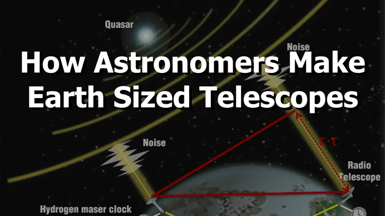
















Radio interferometry uses two or more radio telescopes separated by a baseline to observe astronomical sources, where the resolution depends on the wavelength divided by the baseline length rather than the telescope diameter, allowing astronomers to achieve higher resolution imaging by correlating signals from multiple antennas and measuring the geometric delay caused by the baseline separation.
Radio Interferometry Basics: Two-Element Array Correlation
Added:Basic wave mechanics, including phase, wavelength, and constructive or destructive interference.
The concept of angular resolution and the diffraction limit of a telescope (Rayleigh criterion).
Fundamental principles of radio astronomy, specifically how single-dish radio telescopes detect cosmic radio waves.
Introductory signal processing concepts, particularly the mathematical concept of cross-correlation.
Aperture Synthesis and scaling from two-element interferometers to multi-antenna arrays (e.g., VLA, ALMA).
The van Cittert-Zernike theorem and mapping visibilities to the spatial frequency domain (the UV-plane).
Image reconstruction and deconvolution algorithms, such as the CLEAN algorithm and self-calibration, to remove imaging artifacts.
Very Long Baseline Interferometry (VLBI) and its application to high-resolution astrophysics, such as imaging black hole event horizons.
39.3K views409likes13:24Original Release: 2011-09-13
So what is intererometry? Well, interpherometry is the practice of using a two or more element radio telescope array to observe astronomical sources.
This array itself along with the electronics used to synthesize the signals is what we call the interferometer.
But first why have an interromeer at all? Well, for a for a single telescope, its resolution can be approximated as uh the resolution can be approximated as the wavelength of the source we're trying to observe over the diameter of the telescope. So, um this means that for any given wavelength, if we want better resolution, we need to build telescopes with larger and larger diameters. But building uh large uh diameter telescopes is difficult and expensive. And uh actually lucky for us it turns out that for an array of telescopes like an inner barerometer uh this uh resolution equation modifies to lambda over b where b is the largest separation between any two telescopes and the separation acts as the effective diameter of the array.
So along with being more cost effective and practical to build, an array of telescopes also gives us separate control over the collecting area and resolution of a telescope.
So um let's go ahead and draw what an interferometer looks like. Uh first we have two antennas which we will call antenna uh I and J.
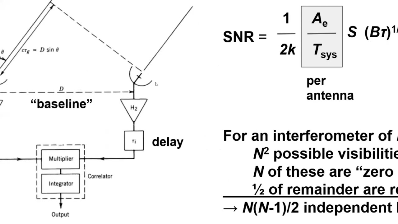
And these two ant antennas are separated by a certain distance uh which we will call the baseline B.
They both point toward a source in the sky in the direction of the unit vector S. So let's draw the source and the unit vector S.
And they will both receive a signal from this source.
So like so.
Um however because the antennas are separated by the distance B they will not receive the signals at the same time.
Because astronomical sources are far away the signals received by the telescopes are plane waves. So we're going to have plane waves coming through the sky.
and hitting the telescopes.
Um, we can see from the figure that one of the antennas, antenna I is just a tad bit closer to the source than the other.
And it is this antenna which will receive the signals first. So the time difference in which the second antenna, antenna J, uh, receives the same wave as the first. So for example, let's say this one um is called the geometric delay and which we will refer to as toao. Um since we know the velocity that the plane wo are traveling at which is just a speed of light c in order to calculate the geometric delay we need to know the extra distance that the wave had to travel in order to reach the second antenna. So we need to know this distance here and this distance is just the baseline vector B. Oops. Um dotted with the unit vector S. So this is B. This distance is B do S.
And knowing this distance like I said we just divide by the velocity of the plane waves. So um the distance is b do s divided by the velocity of the plane waves gives us the uh time delay. So toao is equal to b do s over c.
And now we know the time that it took this wave the extra time that it took this wave to reach uh this second antenna. Now suppose there's a second source in the sky. Let's call it um source two.
So this is two, this is one.
Uh this directional unit vector corresponds to the first source and so will this time delay.
Um so the second source will also cause a geometric delay between the antennas, but it will be different from that caused by the first source because the directional unit vector S will be pointing in a different direction. So this will be shining radiation onto the two telescopes and it'll be at a slightly different direction S vector 2. So it will have a tow 2 V over C.
So um now both the antennas are receiving signals from both sources. Um, and antenna I will receive signals from both sources at time t. So this antenna here and antenna J will receive the signals from both sources at times t minus tow 1 and t minus t to 2.
The antennas themselves can't distinguish between the signals from each source as what they are detecting is a combined voltage from both sources.
Um we can define uh we can actually define this total voltage per antenna though um as E of one at T plus E2 at T is equal to E I at time T. So basically for antenna I uh where E1 and E2 are the signals from source one and source 2 at time t. And then for antenna J, we have signal from source one at T minus to one plus the source signal from source 2 at T minus to 2 is equal to the total signal received by antenna J at time T.
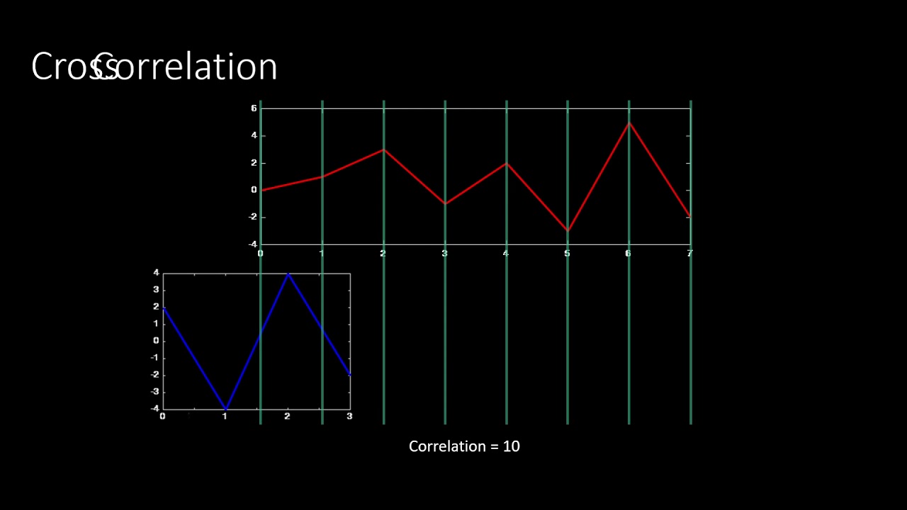
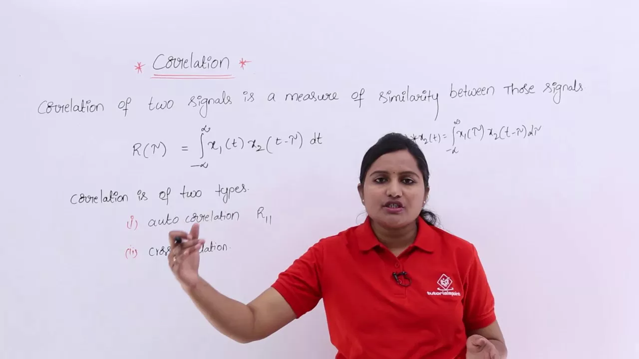
Okay, so if we want to find out information about only one source, we need to correlate the signals from each telescope with each other. And so we run these signals through a correlator which multiplies and integrates the voltages received by the antennas.
So using the correlation equation um f correlated with g at toao is equal to the integral of f at t times t minus to minus to DT.
Um and if we just define our total uh signal per antenna, EI at T as equal to F which we defined earlier as as equal to um E1 at T plus E2 at T and then EJ at T is equal to G.
at E1 T minus T1 + E2 at T minus T 2 and we plug them into the equation. Um let's see what we get. So f correlated with g at to is equal to f of t which is this top one right here is equal to e1 t + e2 t times [Music] time e1 at t minus to1 minus tow can't forget this tow right Okay minus toa plus e2 at t minus to 2 minus toao dt. So normally this would be like a complex conjugate but because we are in the real time valid domain it doesn't really matter. And what we're gonna do now is expand um the integral so that we have okay so because E1 and E2 the signals from the different sources are different and independent from each other they integrate away by averaging to zero as random noise in this term right here.
So these two will just integrate to zero and this term right there. We are then left with the integral of e1 at t * e1 at t minus t1 - t plus e2 uh at t * e2 at t minus t2 minus t dt.
Now in order for these terms to provide meaningful signal information, they must not average to zero as well. Um and this is possible when either uh when TOAO is equal to either negative to one or negative to 2. So let's see toao is equal either to negative to 1 or to is equal to negative to 2. So let's choose to 1. So then the integral would become is equal to the integral of e1 at t * e1 at t since these cancel each other out and that's equal to e1 squared.
So the end result is the average power received by the antennas for either source one or source two depending on the geometric delay in this case the geometric delay for the first source um tow the geometric delay being tow one.
So for a set of tiles we have a set of power values where we have this is equal to this is equal to the power and let's say we have to 1 E1^ squar and we had done to 22.
If we had had like another source for example in the metal it would you know be somewhere on this axis three and so on and so on you know for different time delays.
Um so for a set of towels um we have a set of power values which rise above the signals that could not be correlated and all the other signals that couldn't be correlated are down here as as noise. So we just showed in a very basic way how an interferometer works. The telescopes collect the astronomical signals and the correlator matches the signal functions from each antenna with each other so that they are maximized to give us a power value. So this correlation gives us a one-dimensional image of the sky in a direction parallel to the baseline of the telescope. So we had the sky and we had our two antennas.
Um you know we would know we would have information about the sources in this direction.
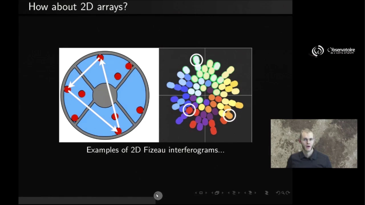
Um, and if we wanted to form a more complete twodimensional picture, we would need another pair of of telescopes.
For example, you know, forming a baseline perpendicular to uh the direction of the first um and this would give us more information about the sources in this direction.
Um so but this right here is more advanced interferometry and this will be covered in another tutorial.
Up Next

15:00
Radio Interferometry II: Fringe Patterns & UV Plane Sampling
@AaronRobertParsons
5.7K views•2011-09-28
61:17
First Billion Years of the Universe with the Square Kilometre Array
@iaaudc
121 views•2022-05-26

6:25
Kepler's Laws of Planetary Motion Explained (Educational Astronomy Video)
@Peekaboo_Kidz
404.9K views•2023-02-17
6:10
Gamma-Ray Bursts: Cosmic Snipers Explained | Astronomy
@kurzgesagt
15M views•2016-07-31
Related Study Plans & Knowledge Roadmaps
Structured learning paths in Astronomy
astronomy
Reionization: Pop III Stars, IGM & 21cm Line
01Foundations of Cosmology & the Early Universe
02Population III Stars & Cosmic Dawn
03Physical Mechanisms of Reionization
+ 2 more learning modules
17h5 modules
Explore Roadmap
astronomy
Planetary Rings: Dynamics, Roche & Resonances
01Foundations of Gravity and Orbital Mechanics
02Tidal Forces and the Roche Limit
03Structure, Composition, and Collisions
+ 2 more learning modules
10h5 modules
Explore Roadmap
astronomy
Asteroseismology: Stellar Waves, Ages & Cores
01Foundations of Stellar Astrophysics & Wave Mechanics
02Stellar Oscillation Modes: P-modes and G-modes
03Mathematical Framework of Asteroseismology
+ 2 more learning modules
35h5 modules
Explore Roadmap
astronomy
Adaptive Optics: Physics, Engineering & Control
01Foundations of Wave Optics and Wavefronts
02Atmospheric Turbulence & Optical Distortion
03Wavefront Sensing Technologies
+ 3 more learning modules
35h6 modules
Explore Roadmap