This video demonstrates through wave simulations that fractal configurations of obstacles are more effective at dissipating wave energy compared to regular grid arrangements, as the irregular, self-similar structure of fractal obstacles creates more complex wave interactions that reduce overall wave energy more efficiently.
Wave Attenuation by Periodic Obstacle Arrays: Mangrove Simulations
Added:Deep Dive
Basic wave mechanics, including concepts of wave propagation, wave height, wavelength, and energy attenuation.

Ondulatória - Conceitos Básicos - Teoria (C42TCT00)
340
A wave is a perturbation of a physical quantity that propagates through a medium, transporting energy without transporting mass; waves are classified by nature (mechanical requiring a medium, electromagnetic propagating in vacuum), by form (longitudinal, transverse, mixed), and by wavefront (point, straight, circular, plane, spherical), with key characteristics including amplitude, wavelength, period, and frequency related by the fundamental equation v = λf.
Click to watch →

fisica 8.2
312
This segment establishes core wave concepts: (1) Wave definition: mechanism transmitting energy and momentum through space, (2) Medium: region through which wave propagates (material or vacuum), (3) Source: body generating wave by perturbing medium, (4) Particle behavior: particles oscillate about equilibrium but don't travel with wave, (5) Energy transfer: wave carries energy from source to receiver, (6) Attenuation: energy absorption by receiver reduces wave amplitude. The segment distinguishes mechanical waves (require material medium) from electromagnetic waves (can propagate through vacuum).
Click to watch →

Revisão Enem: Tudo de Ondulatória!
1.8K
Waves have three fundamental elements: (1) Crest (crista) - the highest point of the wave, (2) Trough (vale) - the lowest point of the wave, (3) Amplitude - the height from the equilibrium position to the crest (or depth to the trough), measured in units of length like meters or centimeters. The amplitude is directly related to the energy of the wave; as waves propagate, they lose energy and their amplitude decreases. The wavelength (comprimento de onda) is the distance between two consecutive crests or two consecutive troughs, representing the size of one complete wave cycle.
Click to watch →

NDA DEMO CLASS | SCINCE | WAVE | BY RUPINDER MAM
116
A wave is a disturbance and vibration that is a form of energy produced when a particle travels from one point to another, storing elastic energy. Waves are classified into mechanical waves (requiring a medium like sound waves) and non-mechanical waves (traveling through vacuum like light waves). Based on propagation direction, waves are longitudinal (particles and wave move in same direction, creating compression and rarefaction) or transverse (particle motion perpendicular to wave direction, creating crests and troughs). Electromagnetic waves have both electric and magnetic properties, are mutually perpendicular, and travel at the speed of light (3 × 10^8 m/s). Key parameters include wavelength (distance between crests), amplitude (maximum displacement), time period (time for one oscillation), and frequency (waves per second). The fundamental relationships are: frequency = 1/time period and speed = frequency × wavelength. According to Planck's theory, electromagnetic wave energy is directly proportional to frequency (E = hν).
Click to watch →
Ondas, conceptos básicos del movimiento ondulatorio
4K
A wave is a perturbation that propagates through a medium, transporting energy without transporting matter; waves can be classified by dimensionality (1D, 2D, 3D), by vibration direction relative to propagation (longitudinal or transverse), and by medium requirement (mechanical or electromagnetic); key wave magnitudes include amplitude (maximum displacement from equilibrium), wavelength (distance between consecutive points in the same vibration state), period (time for one complete vibration), frequency (vibrations per second), propagation velocity (wavelength/period), angular frequency (2π/period), and wave number (2π/wavelength).
Click to watch →
Deep Dive
Fundamental fluid dynamics, specifically drag force, Reynolds number, and flow interaction with solid obstacles.

PC/PSI Nombre de Reynolds. Etude descriptive des écoulements autour d'un obstacle
75.6K
The Reynolds number (Re = ρVL/μ) characterizes fluid flow regimes around obstacles, where Re < 2000 indicates laminar flow and Re > 4000 indicates turbulent flow; the boundary layer concept explains how viscosity manifests only near surfaces, enabling the use of inviscid fluid approximations elsewhere; the drag coefficient (Cx) varies with Re, showing linear dependence at low Re (Stokes' law), constant values at moderate Re, and a dramatic decrease at high Re due to boundary layer transition from laminar to turbulent, which improves flow adhesion and reduces drag force.
Click to watch →

12. Fluid Dynamics of Drag (Part III)
24.9K
The Reynolds number determines whether viscous or inertial forces dominate fluid flow: at low Reynolds numbers (very viscous fluids, slow speeds, small objects), viscous forces dominate and drag follows Stokes's law (proportional to speed, viscosity, and size); at high Reynolds numbers (fast flows, large objects), inertial forces dominate and drag follows an approximate square-of-speed law; the Reynolds number also controls whether flow remains laminar (smooth, steady) or becomes turbulent (chaotic, mixing), with boundary layers forming near solid surfaces where viscous effects persist regardless of overall flow regime.
Click to watch →
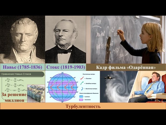
50.5 Задачи тысячелетия
112
Stokes' formula determines drag force on bodies in moving flows, depending on velocity, shape, and surface characteristics. At low speeds, resistance is proportional to velocity; at high speeds, proportional to velocity squared. There are two regimes: laminar flow (smooth, parallel layers without mixing) and turbulent flow (with vortices and mixing). The Reynolds number (Re = ρvL/μ) determines transition between regimes. Laminar flow occurs at low speeds with uniform velocity at any point and parallel flow directions. Turbulent flow involves mixing where particles have different velocities in magnitude and direction.
Click to watch →
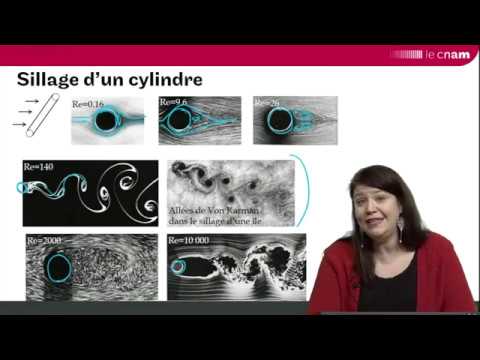
Interactions fluide/solide 2 : écoulement d’un fluide autour d’une particule
7K
The drag force on a particle in fluid flow results from the combined contributions of pressure forces and frictional forces, with the relative importance of each component depending on the particle's shape, size, and the Reynolds number of the flow; at low Reynolds numbers, friction dominates while pressure effects are minimal, but as Reynolds number increases, pressure-related drag becomes increasingly significant due to the formation and growth of the wake region behind the particle, with streamlined shapes minimizing this effect compared to blunt shapes like cylinders or flat plates.
Click to watch →

🔥05 Fluid Mechanics One Shot Video || B.Tech 3rd Semester || UNIT-05 | JE CLASSES B.Tech
303
Drag force formula: FD = 1/2 × CD × ρ × V² × A, where A is frontal area. Drag depends on fluid density, velocity squared, cross-sectional area, and drag coefficient. Reynolds number (Re = ρVD/μ) determines flow regime: Re < 1 indicates laminar flow (Stokes' law applies, CD = 24/Re), Re > 1000 indicates turbulent flow with drag crisis. Drag coefficient is a complex function of Reynolds number, accounting for shape and flow characteristics.
Click to watch →
Deep Dive
An understanding of geometric configurations, specifically the difference between periodic (regular grid) arrays and self-similar fractal patterns.
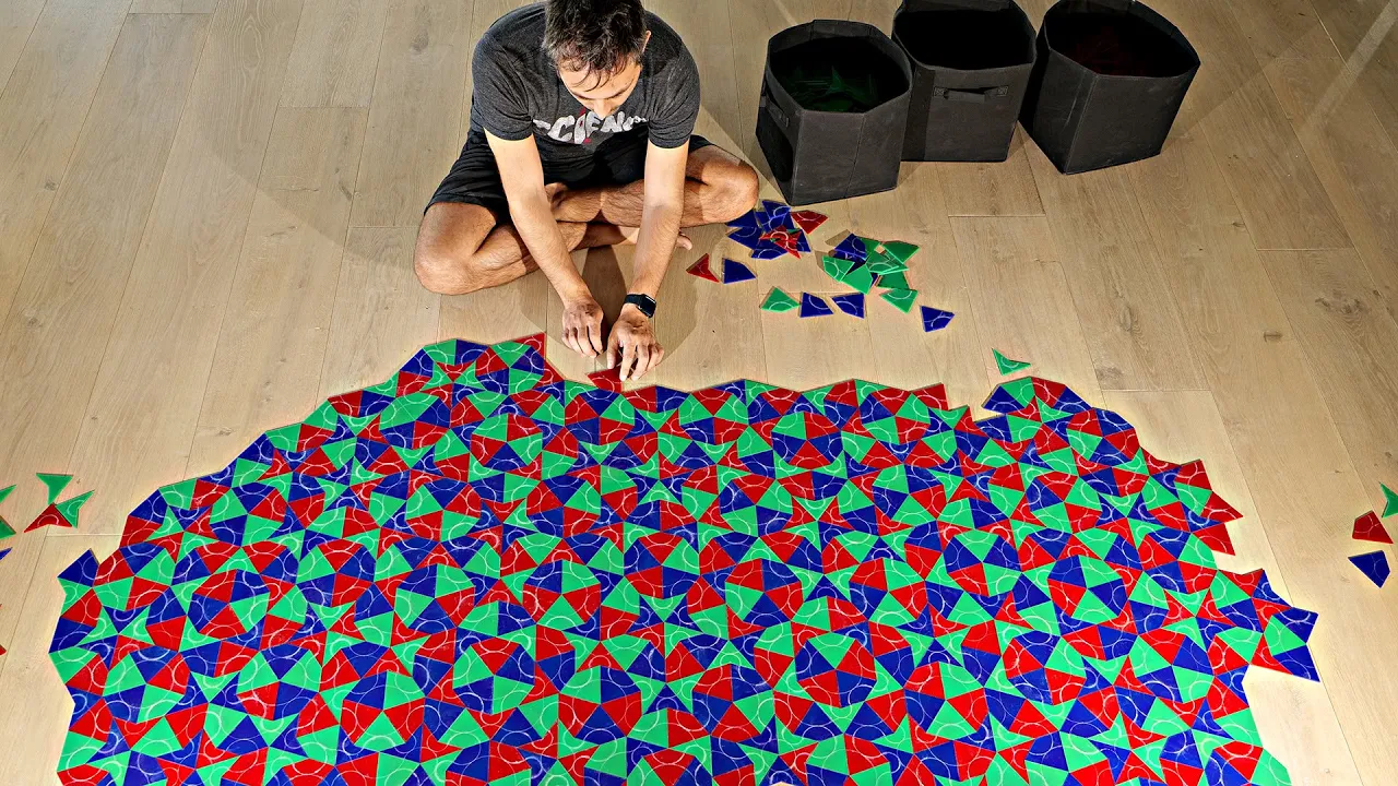
The Infinite Pattern That Never Repeats
21.7M
A tiling is periodic if you can duplicate a portion of it and continue the pattern only through translation with no rotations or reflections. Regular hexagons can tile the plane periodically with no gaps. Periodic tilings can have rotational symmetry: rhombus patterns have twofold symmetry (180 degrees), equilateral triangles have three-fold symmetry, squares have four-fold symmetry, and hexagons have six-fold symmetry. Only two, three, four, and six-fold symmetries are possible for regular tilings.
Click to watch →
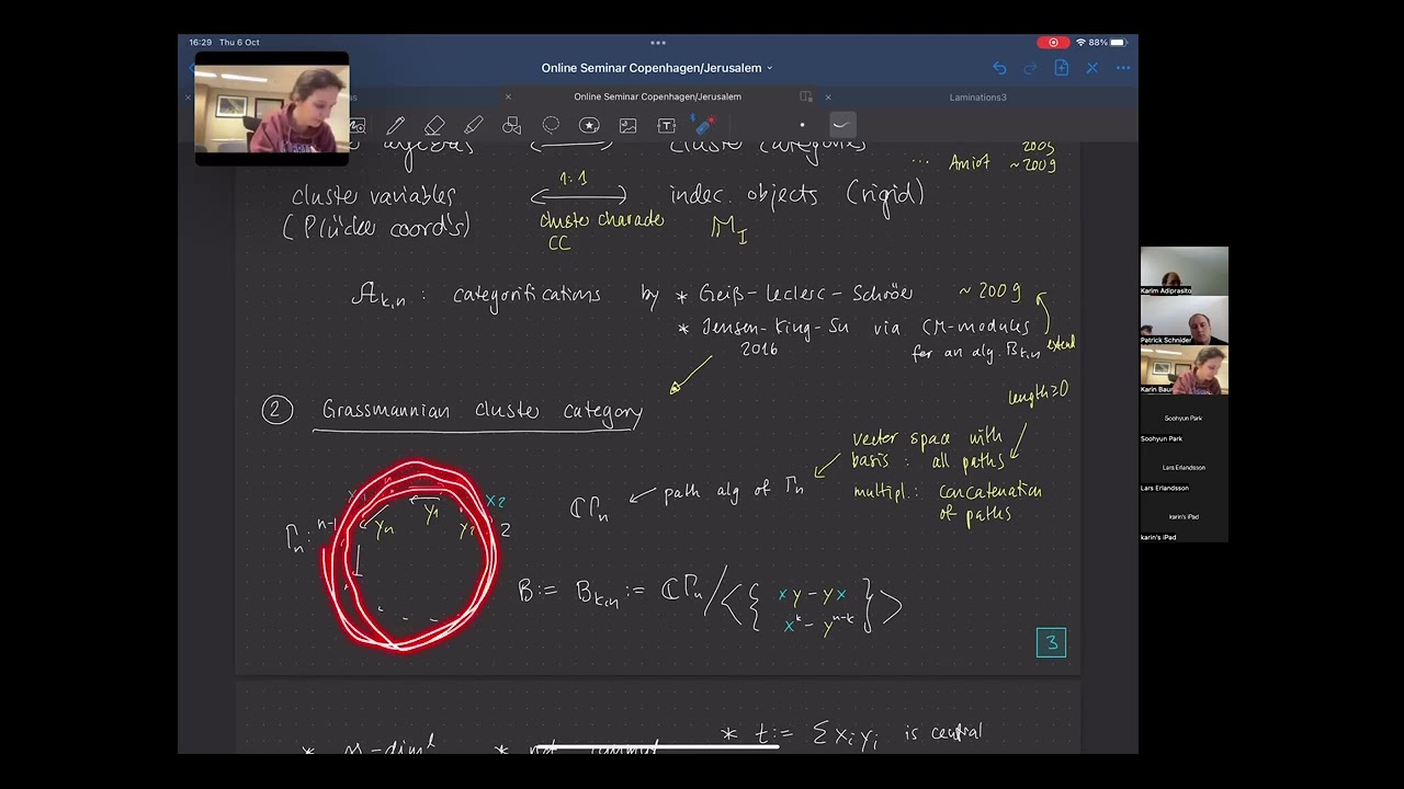
Karin Baur: "Cluster structures for Grassmannians"
142
Frieze patterns are infinite grids with K-1 zero rows, one row of ones, and non-zero entries satisfying K×K determinant conditions. Coxeter and Conway showed K=2 frieze patterns correspond to polygon triangulations, with matching numbers determining the fundamental period. Tame frieze patterns (with vanishing (K+1)×(K+1) determinants) are always periodic with period W+K+1, where W is the number of non-trivial rows. This periodicity reflects underlying combinatorial structures and allows infinite patterns to be understood as repeating configurations.
Click to watch →
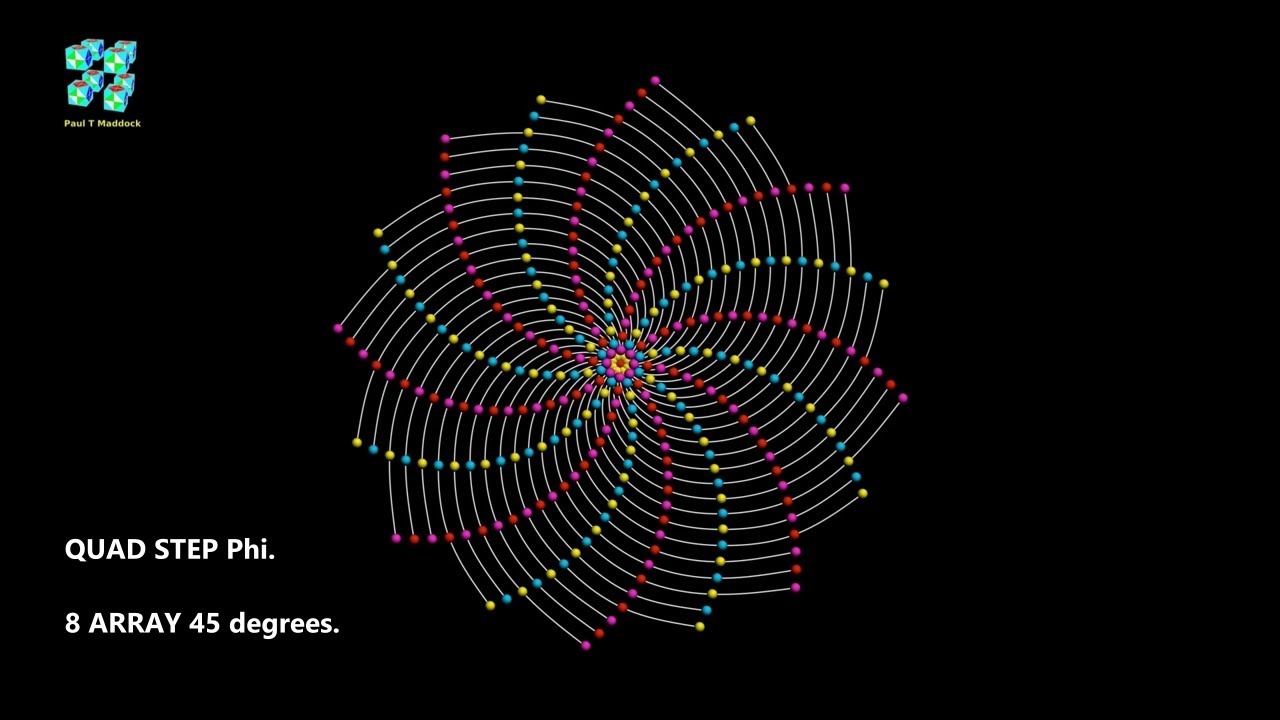
Phi QUAD STEP - 3D QUANTUM HARMONICS.
201
Different array configurations (3, 4, 5, 6, 7, 8, 9, 10) produce fundamentally different geometric patterns. Three-fold arrays resemble sunflower phyllotaxis, four-fold arrays show distinct arrangements, five-fold arrays create symmetrical ten-curve structures, seven-fold arrays introduce rainbow-like color patterns, and eight-fold arrays return to curved patterns. Each configuration reveals unique relationships between array number, symmetry type, and resulting geometric form.
Click to watch →

How a Hobbyist Solved a 50-Year-Old Math Problem (Einstein Tile)
1.1M
A tiling is when you can take a shape or set of shapes and arrange them to cover a plane without any gaps, theoretically extending to infinity in all directions. A periodic tiling has translational symmetry, meaning you can copy the entire pattern, slide it across, and lay it perfectly onto itself. Periodic tilings are common and can be made of more than one shape.
Click to watch →
Lecture 2. Symmetries and Patterns
1.2K
A pattern is a repeated form or design used for decoration, or the regular way something happens. There are three types: geometric patterns, patterns of change, and numeric patterns. Fractals are geometric shapes where each part has the same statistical character as the whole (self-similar when zoomed in). Frieze patterns consist of repeated copies along a line, formed by isometries (transformations preserving distance). The six isometries are: identity, rotation, translation, horizontal reflection, vertical reflection, and glide reflection (combination of reflection and translation).
Click to watch →
Deep Dive
The ecological role of mangroves and vegetation in coastal protection and storm surge mitigation.

How mangroves can protect from storm surge
324
Mangrove forests serve as natural buffers that significantly reduce wave energy and storm surge impacts on coastal areas, providing critical shoreline protection comparable to or exceeding concrete infrastructure; studies show that areas with intact mangrove ecosystems experience substantially less erosion and flooding damage compared to areas where mangroves have been removed, with wave heights reduced by up to 10 feet in some cases.
Click to watch →

Mangroves: Nature's Best Tree? | STUFF YOU SHOULD KNOW
1.6K
Mangrove forests provide critical coastal protection through dense root systems that reduce wave energy by up to 66% over 100 meters of forest width and decrease storm surge depth by approximately 0.5 meters per kilometer. In Australia and Belize, mangroves deposit sediment at 10+ mm/year, sometimes outpacing sea level rise. Historical evidence shows devastating consequences when mangroves are absent: the 1970 Bangladesh cyclone killed 500,000 people partly due to depleted mangroves, and Cyclone Sidr in 2007 caused nearly 140,000 deaths in areas lacking mangrove buffers. The 2004 Indian Ocean tsunami showed 100-meter mangrove forests reduced wave heights by 5-30%.
Click to watch →

PIPK 04
101
Mangroves provide multiple coastal protection functions: (1) Physical barrier - reduces wave energy and prevents erosion; (2) Pollution filter - traps pollutants before they reach the open ocean; (3) Sediment stabilization - root systems hold soil in place; (4) Wind protection - reduces wind speed near the coast; (5) Salt intrusion prevention - prevents seawater from reaching freshwater sources. Mangroves serve as critical nursery habitats for fish, juvenile organisms, dugongs, and sea turtles. Human impacts include deforestation, river diversion, pollution, mining, and conversion to aquaculture.
Click to watch →

Virtual LIVE@Frost Science: Earth Day presented by FPL SolarNow
152
Mangrove forests provide critical storm surge protection and ecosystem services. Everglades National Park contains the largest contiguous stand of protected mangrove forest in the hemisphere. Mangroves have long, intertwined roots that stabilize shorelines and slow water flow during storms. During hurricanes, mangroves can reduce storm surge levels by absorbing wave energy and decreasing water velocity. Research from Hurricane Irma (2017) showed that mangroves prevented approximately $1.5 billion in direct flooding damage and protected over half a million people, reducing damage by nearly 25% in counties with mangrove presence. This demonstrates how healthy coastal wetlands serve as natural barriers against storm impacts.
Click to watch →
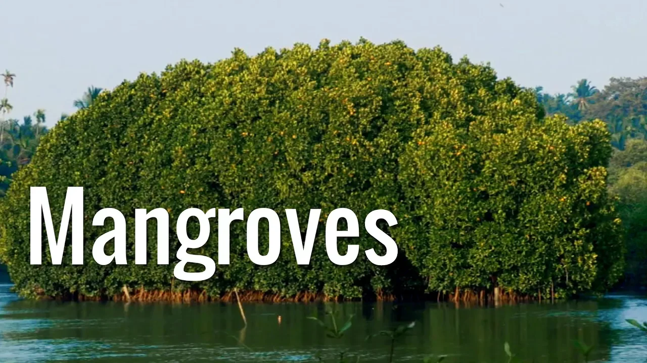
Mangroves | The Guardians of the Coasts
264.2K
Mangroves are salt-tolerant trees and shrubs growing in tidal coasts whose intricate root systems stabilize coastlines, reduce erosion from storm surges, currents, waves, and tides, and provide habitat for numerous organisms; despite over half of the world's mangrove forests having been destroyed by human activities, these vital ecosystems can be restored to protect coastal communities from natural disasters like tsunamis.
Click to watch →
Prerequisite Knowledge
- Concept 01Basic wave mechanics, including concepts of wave propagation, wave height, wavelength, and energy attenuation.
- Concept 02Fundamental fluid dynamics, specifically drag force, Reynolds number, and flow interaction with solid obstacles.
- Concept 03An understanding of geometric configurations, specifically the difference between periodic (regular grid) arrays and self-similar fractal patterns.
- Concept 04The ecological role of mangroves and vegetation in coastal protection and storm surge mitigation.
Subsequent Learning
- Step 01Computational Fluid Dynamics (CFD) modeling techniques for simulating complex free-surface wave interactions with porous media.
- Step 02Biomimetic design of coastal defense structures (e.g., artificial reefs, breakwaters) leveraging fractal geometry for optimized wave attenuation.
- Step 03Physical wave flume testing and scaling laws used to validate numerical simulations of vegetated flows.
- Step 04Coastal zone management strategies integrating nature-based solutions (NbS) with hard engineering for climate change adaptation.
Opening
First Note
Musical Peak
Mid-Section
Climax
Resolution
Finale
End
Opening
1:09Playing Section
- 1
Recording starts with audience applause.
- 2
Ambient atmosphere sets in.
Dynamic Flexibility and Natural Irregularity in Vegetative Wave Attenuation
While periodic and fractal simulations provide valuable insights into how structural geometry affects wave energy, critics argue that these idealized, rigid models fail to capture the true complexity of natural mangrove systems. In reality, mangrove roots and trunks are highly flexible (hydroelastic) and irregularly distributed. Under real wave forces, vegetative structures bend and sway, which dynamically alters their drag coefficients and shifts the resonant frequencies of the system, often leading to different wave attenuation rates than those predicted by rigid, stationary arrays. Furthermore, natural bio-fouling, debris accumulation, and varying degrees of decay create chaotic, non-uniform barriers. Relying solely on rigid, mathematically perfect geometries can lead to overestimating coastal protection efficacy and mischaracterizing turbulence and sediment transport dynamics. Therefore, incorporating flexible structural mechanics and stochastic, real-world irregularity is essential for realistic coastal engineering models.
Deep Dive
Computational Fluid Dynamics (CFD) modeling techniques for simulating complex free-surface wave interactions with porous media.

Free Surface Modeling: Volume of Fluid (VOF) Approach
9.5K
A free surface exists between two immiscible flow phases (like water and air) due to large density differences—air is approximately 830 times less dense than water. Modeling free surfaces introduces serious complications requiring special approaches. Two main CFD approaches exist: interface tracking (Lagrangian grid method) which defines the free surface as a boundary and follows its evolution, and interface capturing (Eulerian grid method) which captures the free surface within a fixed domain. Interface tracking struggles with large amplitude motions without costly remeshing, while interface capturing offers better robustness for complex problems.
Click to watch →
![[CFD] Porous Zones in CFD](https://i.ytimg.com/vi_webp/sOQMXxoKFQM/maxresdefault.webp)
[CFD] Porous Zones in CFD
62.7K
Porous zones in CFD are modeling techniques used when meshing fine geometries like louvers, gratings, or tube banks would be computationally impractical; they are implemented by adding source terms to the Navier-Stokes equations, where the coefficients C1 and C2 (divided by the porous zone thickness) represent the linear and quadratic pressure drop relationships with flow velocity, respectively, and can be derived either from empirical manufacturer data or textbook correlations based on geometric parameters.
Click to watch →
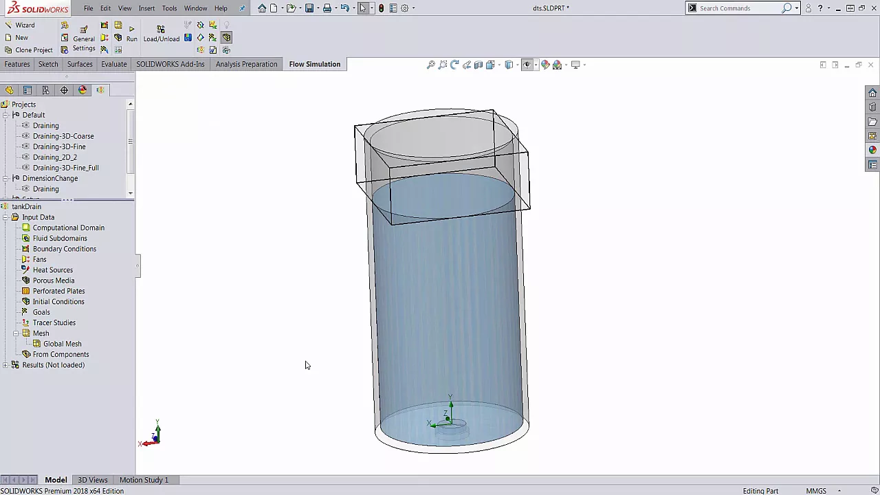
SOLIDWORKS Flow Simulation - Free Surface Flow
68.1K
Free surface flow simulation in CFD enables engineers to model the behavior of two immiscible fluids (fluids that cannot mix) within the same computational domain, using the Volume of Fluids (VOF) approach that tracks volume fractions of different fluids in each mesh cell; this capability allows analysis of phenomena such as fuel sloshing in vehicle tanks, tank filling/evacuation processes, water spout dynamics, and wave resistance on marine vessels, with visualization tools including transient explorers, isosurfaces, and XY plots to track fluid level changes over time.
Click to watch →

Dinámica de fluidos computacional (CFD) en la optimización del diseño de obras hidráulicas
2.7K
The Volume of Fluid (VOF) method is a fundamental technique for simulating free surface flows in CFD. The method works by: (1) Discretizing the computational domain into cells; (2) Assigning a fluid fraction value to each cell (1 for fully filled, 0 for empty); (3) Using an algorithm to track the free surface and assign intermediate values (between 0 and 1) to cells containing the interface; (4) Applying boundary conditions at the free surface to model the interaction between fluids. This approach allows CFD to accurately capture the complex dynamics of free surface flows, including wave formation, splashing, and interface deformation, which are essential for modeling hydraulic structures like desarenadores.
Click to watch →

Simulation of Free Surface with Computational Fluid Dynamics (CFD) Model
642
Free surface flow modeling in Computational Fluid Dynamics (CFD) employs different approaches based on complexity and application requirements: 3D full models solve continuity and momentum equations for detailed three-dimensional phenomena like dam breaks and tsunami impacts; 2D depth-averaged models assume hydrostatic pressure and are suitable for flood simulation and open channel flow where vertical motion is negligible; and 1D models (like Saint-Venant equations) provide the simplest approach for river flow routing and hydraulic jump analysis. The choice depends on factors including computational cost, required accuracy, problem scale, and whether vertical acceleration is significant. Model validation against experimental data is essential to verify accuracy before practical application.
Click to watch →
Deep Dive
Biomimetic design of coastal defense structures (e.g., artificial reefs, breakwaters) leveraging fractal geometry for optimized wave attenuation.

Science outreach with a YouTube Channel: A personal experience
2.3K
Fractal boundaries create unique wave propagation effects. Waves passing through fractal structures like Sierpinski carpet approximations propagate more slowly and have difficulty penetrating the fractal geometry. This insulating effect has practical applications in sound insulation. Natural examples like mangrove ecosystems demonstrate how fractal-like vegetation structures efficiently protect coastlines from storms and waves. The question of whether fractal structure is necessary for wave blocking led to simulations comparing fractal versus regular grid obstacles, showing fractal structures provide superior wave attenuation.
Click to watch →

Marcel Filoche — Water Waves in Hyperuniform and Fractal Structures
122
Fractal absorbers are geometric structures designed to maximize wave absorption through recursive subdivision. Starting from an initial length scale (4 cm), each generation reduces the characteristic length by a factor of 4 (generations 0-3: 4 cm, 1 cm, 2.5 mm). The fractal geometry creates multiple scattering events that couple wave energy to viscous dissipation in the bulk fluid. Experimental results show progressively increasing absorption efficiency with each generation, demonstrating that complex geometries can achieve high absorption without requiring inherently lossy materials.
Click to watch →
2nd Annual Saco Bay Symposium
144
Artificial reef structures designed as three-sided pyramids made of 5,000 PSI marine-grade concrete function as wave attenuation devices. The design features tapered holes that manipulate water velocity and pressure to disperse wave energy rather than refracting and reflecting it. These structures achieve approximately half a metric ton of marine biomass production annually per square meter and have proven stable during hurricanes. Real-world applications demonstrate rapid accretion, with some sites gaining over 60 feet of beach elevation within 39 days of installation.
Click to watch →
Webinar "Gestión de Protección Costera en la Costa Atlántica de la Pcia de Bs As"
119
Breakwaters reduce wave energy reaching the coast, with effectiveness depending on design, wave conditions, and distance from shore. Properly designed structures can reduce wave energy by 50-90% while minimizing disruption to sediment movement. Breakwaters are classified by tide range: micro-tidal (less than 2 meters) requires submerged structures; meso-tidal (2-4 meters) can use either emergent or submerged designs; macro-tidal (greater than 4 meters) requires careful consideration of overtopping. Groins are structures perpendicular to the coast that trap sediment and maintain beach width, commonly used to protect navigation channels from filling with sand. However, they can cause erosion on the downdrift side by interrupting natural sediment transport. Artificial reefs are submerged structures that can create new beaches or restore lost ones by allowing sediment to accumulate behind them.
Click to watch →

Florida Dumped Half a Million Tons of Oyster Shells Offshore… Look What Formed
164K
Oyster reefs act as natural wave attenuators due to their dense, irregular, three-dimensional structure of living oysters stacked on layers of shell. This rough and complex surface absorbs and dissipates wave energy before it reaches the shore at full force. During Hurricane Irma (Category 4, wind speeds exceeding 150 mph), shorelines backed by restored oyster reefs experienced 30-40% less erosion compared to unprotected stretches nearby. Engineers estimated reefs prevented approximately $3 million in coastal property damage during this single storm.
Click to watch →
Deep Dive
Physical wave flume testing and scaling laws used to validate numerical simulations of vegetated flows.

SimCenter | Physical Modeling of Wave Attenuation & Wave Force Reduction, December 4, 2020
350
Laboratory experiments face fundamental scaling challenges: while 1:16 tests achieved turbulent flow, Reynolds numbers remain orders of magnitude below real-world conditions. Ongoing research compares 1:16, 1:2, and 1:1 scales to characterize scaling effects. Prototype-scale experiments at Oregon State's Large Wave Flume use PVC and cross-linked polyethylene to replicate Florida Keys mangrove geometry. Two stem densities are tested: dense and sparse configurations. The 18-meter mangrove zone precedes test walls, with four water depths spanning conditions from maximum projected area to fully flooded root systems.
Click to watch →

Inaugural Lecture of Professor Tom Bruce, Chair of Coastal and Maritime Hydromechanics
486
Research progressed from micro-scale laboratory tests to large-scale facilities in Barcelona. Despite expectations that white water behavior would not scale well, remarkable agreement was achieved between small-scale tests at Edinburgh and large-scale tests at Barcelona for mass of water overtopping and individual wave volumes. This validation demonstrates the reliability of properly conducted physical modeling across different scales.
Click to watch →
Hyde Lecture - Karen M'Closkey
335
Physical scale models can be used for simulation when built for such purposes. The key is setting up clearly defined parameters, testing them, altering them, and making changes as you go. A notable example is Hargreaves Associates' work on Guadalupe River Park, where they built an 80-foot long mock-up to test design flows using colored water to see where eddies would form and where deposition would occur. These became the stabilized and vegetated areas of the banks.
Click to watch →
![[Fluid Dynamics: Physical Modelling] Froude Similitude, Part 3, Criteria and Examples (3/3)](https://i.ytimg.com/vi_webp/4b2W8h7nzUI/maxresdefault.webp)
[Fluid Dynamics: Physical Modelling] Froude Similitude, Part 3, Criteria and Examples (3/3)
822
For high Reynolds number flows (Re > 100,000), viscous terms become negligible, allowing Froude similitude alone to guarantee dynamic similarity. This explains why Froude similitude dominates marine structure testing despite strict Reynolds requirements. Achieving Re ≈ 100,000 for the USS aircraft carrier requires ε = 1400, producing a 0.229m model too small for practical use. Wave parameters scale differently: height scales linearly (H_model = H_prototype × ε) while period scales with √ε. A 12-second ocean wave becomes 1.7 seconds in a 250-scale tank. Forces scale with ε³, requiring amplification by 125,000 for full-scale prediction. These scaling relationships enable translating full-scale ocean conditions into feasible laboratory experiments while accepting minor deviations from strict Reynolds similitude.
Click to watch →
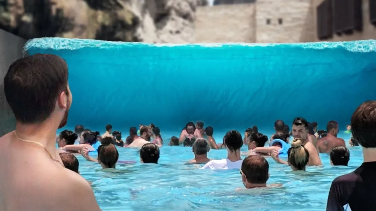
9 Сумасшедших Бассейнов с Волнами, Которые Действительно Существуют
2.7M
The Delta Flume at Delft University of Technology in the Netherlands is a unique wave testing facility. It features a 300-meter long, 9.5-meter high, 5-meter wide channel. At one end, a metal plate is moved by four pistons to generate waves, while the other end has a breakwater to contain the waves.
Click to watch →
Deep Dive
Coastal zone management strategies integrating nature-based solutions (NbS) with hard engineering for climate change adaptation.
![Les solutions basées sur la nature sont-elles bonnes [...] face au changement climatique? - V. DUVAT](https://i.ytimg.com/vi/mYc7XxfARnI/maxresdefault.jpg)
Les solutions basées sur la nature sont-elles bonnes [...] face au changement climatique? - V. DUVAT
108
Nature-based solutions (NbS) are ecosystem-based approaches to coastal climate adaptation that protect natural ecosystems to reduce coastal risks, offering advantages over heavy engineering including lower costs, biodiversity benefits, and reversibility, but they are not universally applicable due to specific ecological requirements, time constraints for ecosystem maturity, and limited effectiveness beyond mid-century as climate tipping points approach; they should be combined with other adaptation strategies in a portfolio approach.
Click to watch →

Integrated Coastal Zone Management for Climate Resilience
869
Integrating nature-based solutions into coastal management involves: (1) Combining natural and gray infrastructure solutions strategically; (2) Identifying the level of services provided by natural assets and their monetary value; (3) Managing natural assets in the long term by local governments; (4) Cost-benefit analysis demonstrating value - a study in Quebec showed breach nourishment had a cost-benefit ratio of 68:1 over 50 years due to benefits from the tourist industry; (5) Examples of successful implementation include the Surrey-Delta-First Nation partnership for living dike solutions and Vancouver's False Creek project using terminology emphasizing restoration of people and nature together rather than fighting against natural processes.
Click to watch →

Third Thursday Science Webinar: Scenarios for future water and sea-level rise adaptation strategies
103
Nature-based solutions can complement traditional engineering in coastal adaptation: (1) Approaches like living with water and creating ecological zones offer sustainable long-term benefits, (2) However, nature-based solutions require time to develop - marshes in front of dikes take years to establish and provide adequate protection, (3) For effective integration, legal frameworks must be established to ensure these solutions meet safety standards comparable to hard infrastructure, (4) A combined approach using nature-based solutions where appropriate and hard engineering where necessary represents a balanced forward-looking strategy, (5) Starting planning now for nature-based solutions ensures they will be ready when needed, rather than attempting rapid deployment under urgent circumstances.
Click to watch →

Learning from the Natural Flood Management Programme and the next steps | WEBINAR
695
Mainstreaming NBS requires addressing three key areas: asset management/recording (maintaining visible records of installed measures to prevent removal), awareness raising (demonstrating effectiveness through evidence), and capacity building (amending processes, providing tools, and training). The US Army Corps of Engineers' Engineering with Nature handbook provides international inspiration. Integration with hard engineering is essential—NBS often serve as upstream complements to downstream defenses. Projects should consider how NBS can reduce the size and cost of hard engineering structures while extending their lifespan by reducing floodwater impact. Climate change demands more resilient, adaptive approaches that NBS inherently provide.
Click to watch →
Episode 5 – Ecosystem-Based Adaptation in the Caribbean
101
Nature-based solutions represent an ecological approach to coastal management that designs solutions motivated by nature to achieve benefits for economy, society, and environment without causing harm. Unlike traditional hard engineering solutions (seawalls, rock revetments), this framework enables achievement of multiple objectives simultaneously: shoreline protection, biodiversity conservation, and social benefits. The Caribbean context exemplifies why this approach is essential—small island nations face unique vulnerabilities including hurricanes, storms, sea level rise, and minimal tidal ranges (only 18 inches), while economies depend on tourism and fisheries. Traditional hard solutions, while quick to implement politically, fail to provide optimal coastal protection. Nature-based solutions offer viable alternatives that manage coastal diversity without prescribing one-size-fits-all approaches, addressing the complex competing interests of coastal zones.
Click to watch →
Opening
First Note
Musical Peak
Mid-Section
Climax
Resolution
Finale
End
Opening
1:09- 1
Recording starts with audience applause.
- 2
Ambient atmosphere sets in.
Dynamic Flexibility and Natural Irregularity in Vegetative Wave Attenuation
While periodic and fractal simulations provide valuable insights into how structural geometry affects wave energy, critics argue that these idealized, rigid models fail to capture the true complexity of natural mangrove systems. In reality, mangrove roots and trunks are highly flexible (hydroelastic) and irregularly distributed. Under real wave forces, vegetative structures bend and sway, which dynamically alters their drag coefficients and shifts the resonant frequencies of the system, often leading to different wave attenuation rates than those predicted by rigid, stationary arrays. Furthermore, natural bio-fouling, debris accumulation, and varying degrees of decay create chaotic, non-uniform barriers. Relying solely on rigid, mathematically perfect geometries can lead to overestimating coastal protection efficacy and mischaracterizing turbulence and sediment transport dynamics. Therefore, incorporating flexible structural mechanics and stochastic, real-world irregularity is essential for realistic coastal engineering models.
Basic wave mechanics, including concepts of wave propagation, wave height, wavelength, and energy attenuation.
Fundamental fluid dynamics, specifically drag force, Reynolds number, and flow interaction with solid obstacles.
An understanding of geometric configurations, specifically the difference between periodic (regular grid) arrays and self-similar fractal patterns.
The ecological role of mangroves and vegetation in coastal protection and storm surge mitigation.
Computational Fluid Dynamics (CFD) modeling techniques for simulating complex free-surface wave interactions with porous media.
Biomimetic design of coastal defense structures (e.g., artificial reefs, breakwaters) leveraging fractal geometry for optimized wave attenuation.
Physical wave flume testing and scaling laws used to validate numerical simulations of vegetated flows.
Coastal zone management strategies integrating nature-based solutions (NbS) with hard engineering for climate change adaptation.
33.6K views921likes3:21@NilsBerglundOriginal Release: 2021-06-27
[Music] [Applause] [Music] [Music] [Music] [Music] [Music] do [Music] do [Music] [Music] [Music] [Music] you
Up Next

74:55
Coastal Ecosystems Science: Vital Coasts Explained | WHOI
@WHOI
536 views•2026-03-05

15:54
Life in Biosphere 2: Sustainable Ecosystems & Human Survival
@TED
334.9K views•2009-06-16
14:30
Microplastics Everywhere: How Plastic Impacts Our Lives
@TEDx
100.9K views•2018-05-08
10:28
Ice Stupa Artificial Glaciers: Solving Ladakh's Water Crisis
@SonamWangchuk66
3.2M views•2015-05-03
Related Study Plans & Knowledge Roadmaps
Structured learning paths in Environmental Science
environmental-science
Ocean Noise: Cetacean Impacts & Mitigation
01Fundamentals of Underwater Acoustics
02Marine Mammal Bioacoustics
03Anthropogenic Noise: Shipping & Seismic Surveying
+ 2 more learning modules
16h5 modules
Explore Roadmap
environmental-science
Road Ecology: Corridors, Overpasses & Fencing
01Foundations of Habitat Fragmentation and Carnivore Ecology
02The Road Barrier: Ecological Impacts of Transport Infrastructure
03Principles of Ecological Corridors and Connectivity Mapping
+ 3 more learning modules
14h6 modules
Explore Roadmap
environmental-science
Ocean Acidification: Kelp Buffering & Shellfish
01Fundamentals of Ocean Chemistry & pH
02Chemical Pathways of Coastal Acidification
03Bivalve Physiology & Calcification Under Stress
+ 2 more learning modules
18h5 modules
Explore Roadmap
environmental-science
Ice Stupas: Glacial Retreat & Water Security
01Foundations of Glaciology & Mountain Hydrology
02Climate Change and Glacial Retreat Dynamics
03The Science of Ice Stupas & Artificial Glaciers
+ 2 more learning modules
14h5 modules
Explore Roadmap