



















The AS5600 is a 12-bit magnetic rotary position sensor that measures angular position with approximately 0.08789° resolution by detecting the rotation of a diametrically magnetized magnet positioned 0.5-3mm above the sensor; it uses four Hall effect sensors inside the chip to convert the magnetic field changes into a digital value, which can be interfaced via I²C to microcontrollers for applications like tracking stepper motor rotation with high precision.
AS5600 Magnetic Position Encoder for Stepper Motors: Review & Code
Added:Fundamental principles of stepper motors, including step angles, phase excitation, and the limitations of open-loop operation.
Basic Arduino programming proficiency, including importing external libraries, using the Serial Monitor, and basic input/output operations.
Introduction to the I2C communication protocol, including device addressing, SDA/SCL lines, and master-slave architecture.
The basic physics of Hall-effect sensing and how diametrically magnetized magnets are used to measure angular position.
Implementing closed-loop feedback control systems, such as PID algorithms, to automatically correct for stepper motor step loss.
Exploring Field Oriented Control (FOC) for brushless DC (BLDC) and stepper motors using advanced libraries like SimpleFOC.
Comparing I2C-based magnetic encoders with high-speed SPI alternatives (like the AS5047D or AS5048A) for latency-critical applications.
Integrating magnetic encoders into complex motion control systems, such as robotic arms, CNC axes, or precision camera gimbals.
159.3K views2.5Klikes48:18Original Release: 2021-03-05
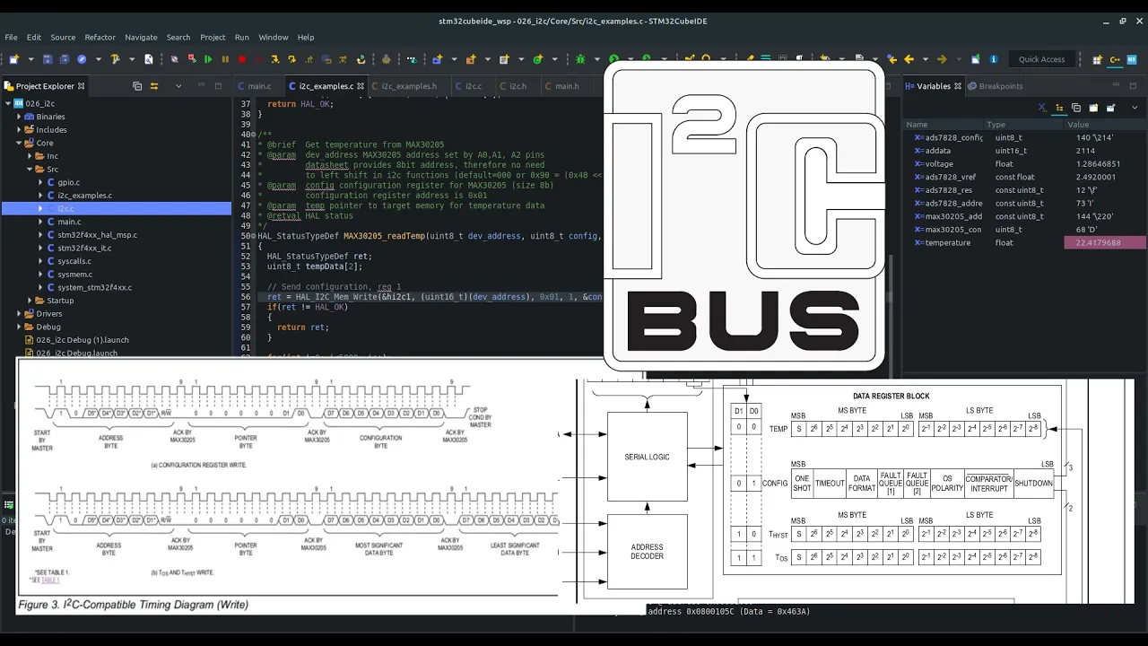
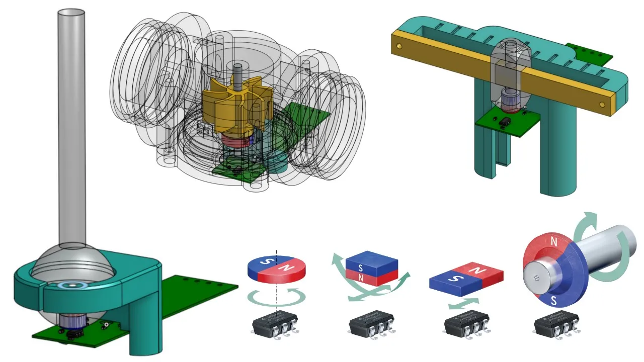
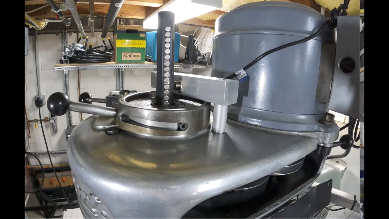
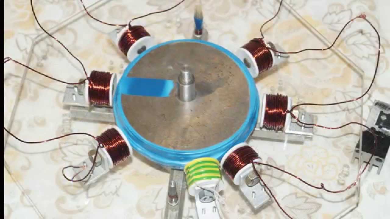
welcome everyone in this video i'm going to show you another type of encoder and this time it is the as5600 magnetic rotary position sensor so it is this tiny chip here i covered this pcb with a small piece of captain tape but it's just a small white pcb two by two centimeters and it has seven pins as you can see for us now it is only four pins which are useful vcc and gnd to provide the power which is five volts and then scl and sda because this circuit uses an i squared c interface so you can just use the clock and data pins and connect this stuff to a microcontroller and to introduce some change to my projects i am using an arduino nano this time but you will be able to use this with any kind of other arduino based microcontroller because this project is purely based on i squared c so whenever you are looking for the wiring you just have to look at the i squared c pins on your specific microcontroller whether it is a nano or a you know or an stm32 blue pill or something then just look for the i squared c interface but in fact this thing can also output bwm signal and based on the pwm signal you can also get the angular position but this time we are relying on the digital values so how this work is that this chip contains four carefully placed hole sensors inside the casing and it requires a special magnet which has to be positioned above the chip roughly from 0.5 millimeter to 3 millimeters so it has to be relatively close and this magnet has to be magnetized in a special way so usually when you have a magnet then you have a north and south pole on the top and the bottom of this cylinder so if you look at this tiny thing then yeah the top and the bottom of it but this guy here is magnetized in a different way so it is uh diametrically or diagonally magnetized which means that if you imagine a cut across the diameter of this then one side will be the south pole and the other side will be the north pole of the magnet and this is very important because as you rotate this thing then the north pole and the south pole will like show in different or point in different directions like the needle in the compass so this works in the same way and that kind of rotation will be registered with this thing and then by a 12-bit ad converter it will be converted into a digital value so the 12-bit also means that we have a 4096 different positions which can be registered as different position using this magnet and that also means that we have less than one tenth of a degree resolution in terms of angular resolution and that is very nice and later on i will tell you more details about this but i want to show you the practical application here so as i mentioned i'm using an arduino nano here this time but you can replace it with any kind of microcontroller which is capable of working with i squared c so one i squared c device is this guy here the magnetic sensor and another one is this uh oled display nothing fancy we will only print the angular position on this thing and then what i did here is as you can see this is a stepper motor i put a knob here from a potentiometer and then we have the circuit here so what is here on the back side is i printed a small piece of plastic which can accommodate this sensor like this and then i have this kind of standouts or i don't know how to call them to provide the proper distance between the back of the stepper motor and the surface of this chip so then this is put together so we assembled it and then this is screwed on the back panel and actually i will disassemble it right now just to show you how it works so i just used two screws to fix everything and then two other screws to fix the sensor to the plastic plate and then i will disassemble this and now you can see this is a new version of plastic case as compared to this i did some several iterations so this is how the sensor is situated on the back panel of this but we don't stop here because as i mentioned we have to have a magnet somewhere somewhere where something is rotating and since we want to register the rotation of the shaft of the stepper motor we have to add this thing to the shaft so now you can see that the magnet is there but i will further disassemble this thing to show you the inside of the stepper motor so this is the inside of the stepper motor and you can see the different coils we have eight coils here you can see the teeth which help the alignment of the stepper motor and then here is a bearing and then actually you can see that at the end of the shaft i have the magnet i tried to center it as much as possible this is how it turned out it's slightly off-centered but it's okay and what i actually did i put a tiny drop of super glue on the shaft and then i applied the magnet on it because fun fact the shaft is not magnetized so it's probably some aluminium or some kind of steel which is not magnetic i don't really know but it's not really magnetic and then that's a big problem because when you try to apply the magnet on the shaft then it tries to move towards the bearings which is actually magnetic so then that's another reason why i use the super glue to help the shaft to help the adhesion between the shaft and the magnet and keep the magnet there where i want to want it to be so yeah so this is the stepper motor and then you can see that the four outputs are here and and technically that's all so i just applied the the magnet and then i just assembled everything so here you can see the back side which goes back here so this is the small cup for the bearing and then there is some kind of uh wavy washer so i guess it has a sort of a spring effect so when you put this on the bearing and then you put this on top of it then the bearing will be actually pushed towards the inside of this casing so something like this so now this is assembled and you can see that there is the tiny magnet and it's slightly inside the uh casing so it does not stick out and then i just measure the distance between this magnet and the top of the chip so i tried to print this uh plastic stuff in a way that it will provide the optimal distance between the magnet and the chip so yeah and now i actually just use two screws to keep the housing intact and then i use the other two slots or screw holes to fix this on the back panel so it turns smoothly and then i just put this chip over this and then i use slightly longer screws of course because then i extended the distance between the end of the screw hole and the the hole there so so this is fixed and unfortunately it's not too visible in the camera but there you should see the chip in the gap and then this distance is just fine for the for the chip so now i have to remember the connections so i just connect this usb to the arduino and then we see what happens so here's the welcome message and we get stuck here until the magnet is not registered so sometimes i have to move this so now we are at zero degrees and then i start to rotate the shaft and then we increase the absolute position in terms of angles or degrees sorry so then i will do a full rotation and this should show i will try to position this to yeah 360.
so this is one uh full rotation do another full rotation we are there 721.
so one reason behind the flickering is that whenever a new value is registered the screen is being updated and the way it updates the screen is that first it deletes the content and then writes the new value and since i'm using this wacky cables sometimes it can happen maybe that some noise is being picked up so therefore this thing thinks that there is a new angle and since the angles are very close to each other it's very easy to pick up the noise but you can see that i rotate this thing then the angle is just climbing up and up and obviously if i turn counterclockwise then soon it will reach zero and then of course it should go to negative values and there is there's the negative value so now this works and it's relatively simple but actually there are a few tricks behind the scenes on the microcontroller because i had to do some tricks with the coding for example how to detect a full turn and how to make sure that we are printing the absolute position and so on and so on so now i will move to my computer and i will show a bit more details first about this so you can understand uh better how it works and after that i will show you the code line by line and you can understand how to program this and how to use it for other applications and obviously i will also upload some other videos where i show some more application other than just registering the stepper motor here and printing it on a display so let's move to my computer and let's dive into this microchip okay so before i show you the source code and some other things i would like to show some extra information regarding this uh encoder so let's start on the top left corner figure 35 so you can see the four different arrangement here uh with 90 degrees separation from each other so if the north pole of the magnet is facing towards the top of the chip so you can see the pin number one uh here and the south obviously then facing downwards then that's the zero position and this is like a physical position as well as long as you don't burn a different uh configuration into your chip so whenever you place the magnet exactly like this you will read zero degrees and then if you start to rotate the magnet in the positive direction which is the clockwise direction then if you do a 90 degrees rotation then the north pole is facing towards the right as you can see it here and the south pole is facing towards the left of the chip then you read one-fourth of the total value of the digital output so this is 1024 and if you keep rotating the chip or the magnet uh another 90 degrees so you end up at 180 degrees so from this you went upside down you read half of the maximum output as you can see and then at 270 degrees you have the three quarters of the total output and then if you go back to zero then of course you read zero so this is how it works and then of course if you are in between these values then you get some fraction of these numbers and on figure 40 here on the right side you can see exactly how the magnet should be magnetized so instead of having the south pole on the top and the north pole on the bottom or the other way around you have the north and south on the sides of this magnet and then here you can see how everything should be aligned so of course the surfaces should be parallel and then the gap should be somewhere between 0.5 to 3 millimeters according to the data sheet so so this is how i also tried to align everything and this is why i printed that small plastic stuff to have the proper distance between the surface of the chip and the surface of the magnet and on the left side on the bottom section of the picture you can see the table for the different registers we don't care about most of the things we only look at these two lines here and this line so the top two lines which i highlighted here those registers give us the full number for the digital value of the angle and here we are reading two 8-bit uh registers so that is 16 bits of information but the converter itself provides a 12 bit number so in the coding i will show you how to work around this and then in the bottom section here actually this status register is explained in this table so if one of these values are 1 then you have to see what is written in this other table in the table 23. so if the mh bit so this guy here is high or equals one then the magnet is too strong so this gap right here is very tiny so you have to separate the the magnet from the chip a bit more if you read the ml as high then the magnet is too weak so either you don't have magnet at all or the magnet is not close enough so you have to decrease the distance between the chip surface and the surface of the magnet and then if you have the md magnet is detected then you have the optimal configuration so that's very nice and then before going uh to the arduino code i would like to show you something regarding the resolution of a stepper motor and the resolution of this thing so we said that this is a 12-bit uh instrument so that equals to 4 096 different levels and then if we divide a full circle into 4096 equal parts that will be roughly 0.08789 so that means that for example if you read zero so you are at the zero degree and you read one then you did this small amount of angular deviation on the on the on the shaft or with the magnet as compared to the surface of the chip so this is the angular resolution basically and then another resolution for stepper motors is the micro microstepping so let's consider a regular nema 17 motor which has 1.8 degrees resolution so that means that with the different microsteppings we want to look at uh different angular resolutions so that means that for example if we are using the 200 microstepping which is the default then we have 1.8 degrees resolution so you can see that if you multiply these two numbers you get 360.
so now if we increase the microstepping then we get of course 0.9 then if we again increase the microstepping we have 0.45 degrees so one step with the motor will move the shaft with 0.45 degrees so now we are entering higher region here so 0.225 so now 3200 microstepping so this is 0.1125 and if we go to this then 0.05 so you can see that the boundary is technically here because the the angle is still larger than the angle deviation that we can register with the with this magnetic sensor so if you use a 1.8 degree resolution stepper motor and you use 3200 as the microstepping setup you can still register every steps from the stepper motor but at 6400 times microstepping you cannot catch all the steps because the stepping on the stepper motor is finer than the resolution of the magnetic sensor as you can see so you can go to 3200 and that's quite a decent angular resolution i would say so this was just some extra information and now i show you the code behind the device that i showed you in the demonstration so finally let's look at the arduino code so we have the wire library which is for the i scratch c and then we have two other libraries for the oled display as well and these are just some standard line for the address and all the other things of the oled display and then i also define the timer which will help us to keep the updating in control so you won't try to update the display continuously but just in a certain period of time so that's what we have i also gave some tips here regarding the connections for the i squared c so these these are the pins where you should connect uh the display as well as the magnetic encoder and then we have a bunch of variables here for the positions and so on for the magnetic encoder so this thing will take care of the status register and then the low byte and high byte here is responsible for the reading of the position related registers so we have two registers that we have to read and one register contains 8 bits from the 12 bit number that we have and another register will contain only four bits uh of useful data for us so we will read them out and then combine them uh to a so-called row angle and the row angle is the number between 0 and 4095 and this has to be converted into degrees angle so that's the the angle here and then i divided the full circle into four parts quadrants so we take care of those in this two or these two variables and they are important when we try to register the number of turns so another variable where we keep track of the number of turns we have to tear the value or we want to tear the value to keep track of the rotations properly so we have a corrected angle variable we have to save the start angle because you cannot be sure that when you start the microcontroller the magnet is perfectly aligned with the encoder so it will show zero value so then we use this start angle to tear the value of the encoder and then we have the total angle and that is the absolute position of the encoder or the magnet so for example if you did 10 total turns of the shaft or of the magnet then that should show 3600 degrees so that is the 10 turns equivalent angle and this variable will help us to keep track of the change in the total angle so this will also help us to print the updated values in a more let's say economical way then we enter the setup part so we start the serial you don't need it and if you don't communicate with the computer just comment out all the serial related things from this code because uh you just don't need them so they should not use the resources of the microcontroller so we start the i scratch c communication and we start it with a faster clock and then we check the presence of the magnet and this will be a blocking function so the rest of the setup will not be performed as long as this cannot exit with a let's say positive outcome so if the magnet is properly aligned this just runs twice and then it will exit and the next things will be performed line by line so let's say that this was successful so we do a reading so we know where our magnet is right now and that angle will be registered and saved into this start angle variable so that will be used for tearing the value and these are again just some random or not random but these are just some general lines which are needed to run the oled this is also borrowed from the adafruit library so we set the font we clear the display i set up a larger font size and then here is some kind of welcome message in fact it's good to introduce some delay here so the user can actually see the welcome message on the display for a few seconds and then here i just start the timer for the oled display so the code will know when to print a new value or when to try to print a new value and then here we have four functions so we read the angle and then we make the correction we check the quadrants and then we refresh the display and i also put a delay here but it's not necessarily needed but you can play around with this so the more often you read the values the better resolution you have but your resolution will not be improved but you will see the changes more often that's what i mean by better resolution so maybe if you read it at every uh 200 milliseconds you can register every 10 degrees of rotation at a certain rpm but if you read it at let's say 100 milliseconds as it is shown here then you see twice as much values so let's see what are these uh functions so the read row angle is the following so we start to communicate with the sensor which is located at this address and we send this value to the register and we finish the transmission and then we request one byte from the i squared c device which is the magnetic encoder this time so we wait for it and then we put that value in the low byte and then we do the same but we communicate with the other register which contains this portion of data and then we do the same practice so we finish the transmission and then we request one byte or eight bits from the uh encoder and then we just put it in the high byte and now comes the magic so we read out 16 bits but our number at the end will be 12 bits so what we do is that the high byte will be shifted by eight bits towards the left and what is happening is illustrated here so what we did is that the initial value was uh 16 bits right here and then let's say just for the sake of simplicity this was all four and now we want to shift this towards the left by eight bits so technically we just move this wall group uh towards the left by eight uh positions so what you see here uh in in this line is they are located on the rightmost part and then now they are moved here so they are moved to the left by eight so this is now filled in and then since we have also the low byte we can combine it and the combination in this case is the bitwise or operation so whenever you put the numbers on top of each other like this you have to check the first place and see if one is there so here if one of the values is one then the result will be one and you just do this step by step so you move to the left and check that okay this is one so i write down one here and then here for example you see zero and you see zero on top of each other so that will be zero and so on and so on so you go on and this will be your final result so this operation is the one that we do here and finally we have our number so this is the 12 bits which i highlighted here stored in a 16 bit variable an integer or int that's also 16 bits and then now we can convert this into the degrees angle because this 12-bit number represents our uh angle angular position in between 0 and 4095 but we have to know this in degrees so what we do here is just this and and and this number is technically here you can see so 360 divided by 4096 so then you just multiply the bit values with this tiny value which is also your resolution angular resolution and you get the angle in degrees so then the next function is the correct angle which is the tearing and what we do here is we already read the start angle so whenever we get a degree angle uh then we just subtract that value but there will be a problem with this so i will show another picture soon so if the number becomes smaller than 0 so it becomes a negative number we have to sort of normalize it and what we do is that if the corrected number or the corrected angle is smaller than zero so if it's a negative number we add 360 to that number and that will be our refreshed value so as i wrote here for example if we get minus 15 degrees then we have to add 360 to that and that becomes 345.
so for this i want to show you some kind of illustration because it's very important to understand this so here is our full circle which is either 360 degrees or zero degrees and then of course we have 180 and 270.
so i will show you why do we need the correction in in the angles so let's say we have some kind of starting angle which is this number here and let's say that this is 60 degrees so you have to do a tearing and that is technically 60 degrees minus 60 degrees here when the magnet is in in this position so the technically what you see is that the north pole is just facing this direction and then uh we start to read the the rotation so we get larger and larger numbers uh so this becomes the starting point the the new origin and we go in this direction so let's say we read 61 and that will be translated to 1 and then we read 80 that will be translated to 20 and so on and so on but if we get any numbers in between 0 and 60 so in this portion of the circle then we are in trouble why so let's say we read something here and let's say that that is 45 degrees so if we read 45 degrees as an angle that means that the third value will be 45 degrees minus 60 degrees so that's minus 15 and whenever we are looking at this scale we see that we only have positive numbers and of course as a human you can see that uh minus 15 is just 15 degrees towards this direction but the code or the the software does not know this so what we have to do is uh the correction uh should be done and that is technically just we have the minus 15 and we have to add 360 to that so then what we do is we do this operation of course and this is uh 340 and then we just count uh from from the original position here uh 345 degrees so we arrive here and this is 345 degrees and now we know that we are placed here so every time we get a smaller number than zero when we tear our angular displacement then we have to correct it and add the 360 to that number and then that that will solve our problem and since we are here and i have this other circle i will explain you another thing so you can see that this is divided to four equal parts so this is the first one this is the second one the third one and the fourth one and why they are important is because we want to register the number of turns and one foot turn is when you did 360 degrees and you move towards the first degree again so technically this kind of transition if this is your positive direction so what you should do is you have to see when you passed uh basically the zero degree mark but that's not just uh just a simple task because for example if you rotate your shaft very fast or you cannot catch up with the readings then you cannot exactly see that for example the angle went from 359.99 something to 0.00 something so this is uh not possible so what you can do is as you can see we divided the full circle to 90 degrees portions so four quadrants here and we just look at the uh transition between quadrants and this is the most simple thing is that we look at the transition either from four to one which is the positive direction or 1 to 4 which is the negative direction so what you do here and i will show this in the code as well is whenever you get a transition between uh the fourth quadrant and the first quadrant so you went from four to one you increase the number of turns and then the other way is that when you went from quadrant one to quadrant four is that you decrease the number of turns so you went towards the negative uh direction and then this is more easy because you can decide that your quadrant is 4 when you are between 270 and 0 and your quadrant number is 1 when you were between 0 and 90 degrees and of course you can refine this by for example registering this uh transition this transition and this transition as well so then your number of turns can be updated at every one fourth of turn or you can further decrease these areas and then you have this kind of transition this transition this this and so on and so on so you have several more transitions but of course your code should be able to catch up with these smaller transitions so here for example instead of checking the transition only at 0 and 90 degrees you also check it at 45 degrees so this was the explanation for the number of quadrants so i go back to my code and show you how this works in in the in the arduino so these are the quadrants and these are the definitions so if the corrected angle is larger or equal to zero and smaller and equal to 90 we are in the first quadrant so in this portion if we are between 90 and 180 we are in the second so we are here and so on and so on so this is how it works and i also printed it out when i needed it and here we look at the transitions so this is when we register whether we did one full turn in the positive direction or one full turn in the negative direction so first of all we look at the changes so if there was a change in the quadrant number so there was some kind of transition then we check for two cases one is when the current number is one and the previous was four so we went from four to one so that was a clockwise rotation so we did a full turn in the positive direction so we increase the value of it by one and if we did the other way around so if the quadrant number is four right now and the previous was one that means that we went backwards so we did a counterclockwise rotation and the number of turns has to be decreased by one so that's what we do here and yeah i put this command here as well so as you can see the transitions can be checked more often but for us this is just fine and here at the end before this part of the code finishes we update the previous quadrant number with the current one so we can look for the next uh transition and after all this is done and this is very important that this has to be done before the next operation we calculate the total angle so the absolute position of the shaft so we take this multiplication here so the number of turns times 360 plus the corrected angle and how this works is that for example if you just started to use this thing then the number of turns is zero so this part becomes zero and we just add the number between zero and 360 to to the zero here so when we are in our first uh turn we just use the corrected angle but then we did let's say two turns so this becomes two then the wall expression in the parenthesis becomes 2 times 360 which is 720 so then we have already the two turns plus we add the corrected angle to that so then we can increase 200 by 200 degrees for example so that will be 920 and so on and so on and then i printed this but when you when you are using the display without any kind of connection to the computer this has to be commented out and then we have to check the presence of the magnet so while this thing is not true or yeah basically while this thing is not true this expression we keep the code running in between these brackets and what this means is that we are looking for the md equal one status and that is when the status registers sixth bit becomes one so that's when the md equals one and that is 32 in decimal numbers then we keep reading the things and that's what happens so we start to communicate with the sensor we want to read this status register and then we get the status from it and then i also print it as a binary but this can be again commented out and then this keeps going on and on as long as the sixth bit doesn't become one and then this can exit and print that the magnet was found and wait a little bit so then we have the last function which is the refresh display function so we check the elapsed time and when there is 100 milliseconds elapsed we enter this part and then we also check if the shaft was moved or not because if it's not moved then obviously we don't want to update the display so we just exit everything but if the total angle is not it does not equal to the previous total angle then we can enter this part and we clear the screen we update the most recent value we reset reset the timer so we can count 100 milliseconds again and then we update the previous total angle with the current total angle and and that's all so i think it's a good idea to have these kind of conditions in your code because uh maybe you already fulfilled this condition but if the value hasn't changed then why would you change it and why i do it like this is because you don't want to maybe check this every time when your loop iterates a cycle so you just want to check it at every i don't know 1000 iterations i don't know what's the time of one iteration but let's say this is 1000 iterations so then you don't check it at every iteration so this is why first i check with the time and then with the change and here also you can define a tolerance as i wrote it here because sometimes since the angular resolution is very fine uh the magnetic encoder can register slightly different uh angle but this is like plus or minus one bit equivalent of angle so it's not a big number but it's enough to trigger the whole things here so what you can do instead is that you add the small tolerance of course if your system can allow this so you don't don't need that much precision so you add let's say a few steps of tolerance let's say two three or four bits and then if the next value is outside of that tolerance then you enter this part and update the display so let's say instead of every 0.0 um 88 degrees which is like one step roughly uh you update at every zero point 176 degrees so at every two two steps of tolerance and so on and so on but this is up to you but yeah as you can see this was the last function in the loop and now you could see how this thing works so what i will do i will put this sensor in some of my projects i ordered several of this thing so i just have to print some new plastic mounting brackets and then i will add this to my milling table for example and i will also do some other things where i need this kind of encoder so you will see those videos as well i hope you learned something i tried to share all of the relevant details which can be useful for this kind of sensor if you have any questions or suggestions or or comments uh please leave a comment and we can discuss it in the comment section uh once again i hope you learned something and see you in the next video
Up Next
17:48
Steppers vs Servos in 3D Printers: An Engineering Analysis
@MadeWithLayers
280.8K views•2025-10-07

30:32
Ultrasonic Transducers: Resonant Frequency Measurement and Horn Design
@imajeenyus42
229.9K views•2017-02-22

54:16
Polymer Environmental Degradation: Mechanisms & Stabilization
@iit
1.8K views•2012-07-10

33:39
How a Student's Question Saved a NYC Skyscraper from Collapse
@veritasium
22.8M views•2025-04-26
Related Study Plans & Knowledge Roadmaps
Structured learning paths in Engineering
engineering
Building Acoustic Levitators: Physics & Arduino
01The Physics of Sound and Standing Waves
02Piezoelectric Transducers and H-Bridge Drivers
03Arduino Programming: Generating 40 kHz Signals
+ 2 more learning modules
14h5 modules
Explore Roadmap
engineering
Building Peltier Cloud Chambers: Particle Tracks
01Cosmic Rays & Cloud Chamber Physics
02Thermoelectric Cooling (TEC) Fundamentals
03Custom Liquid-Cooling Loop Design
+ 2 more learning modules
18h5 modules
Explore Roadmap
engineering
Yagi-Uda Antennas: Modeling, Build & VNA Test
01Introduction to RF and Antenna Fundamentals
02Yagi-Uda Antenna Design Principles
03Antenna Modeling and Simulation in 4NEC2
+ 2 more learning modules
18h5 modules
Explore Roadmap
engineering
ECG Monitor Design: Op-Amps, Filters & Noise
01Electronics & Breadboard Basics
02Op-Amps and Instrumentation Amplifiers
03Bioelectricity and ECG Fundamentals
+ 2 more learning modules
18h5 modules
Explore Roadmap