




![[일단계 아두이노]18강 아날로그핀 개요/가변저항 실험 1](https://i.ytimg.com/vi_webp/tXXaCdFZNLk/maxresdefault.webp)


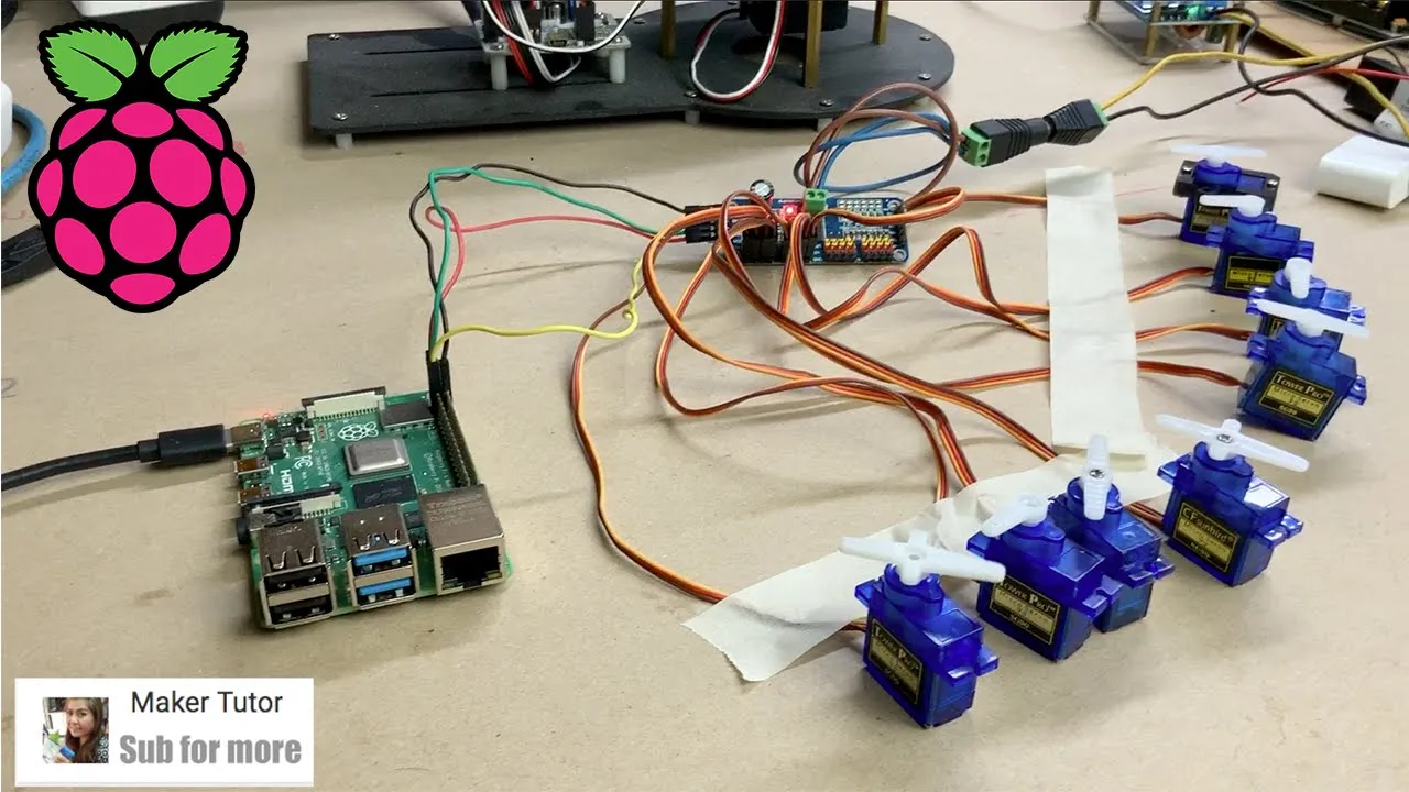

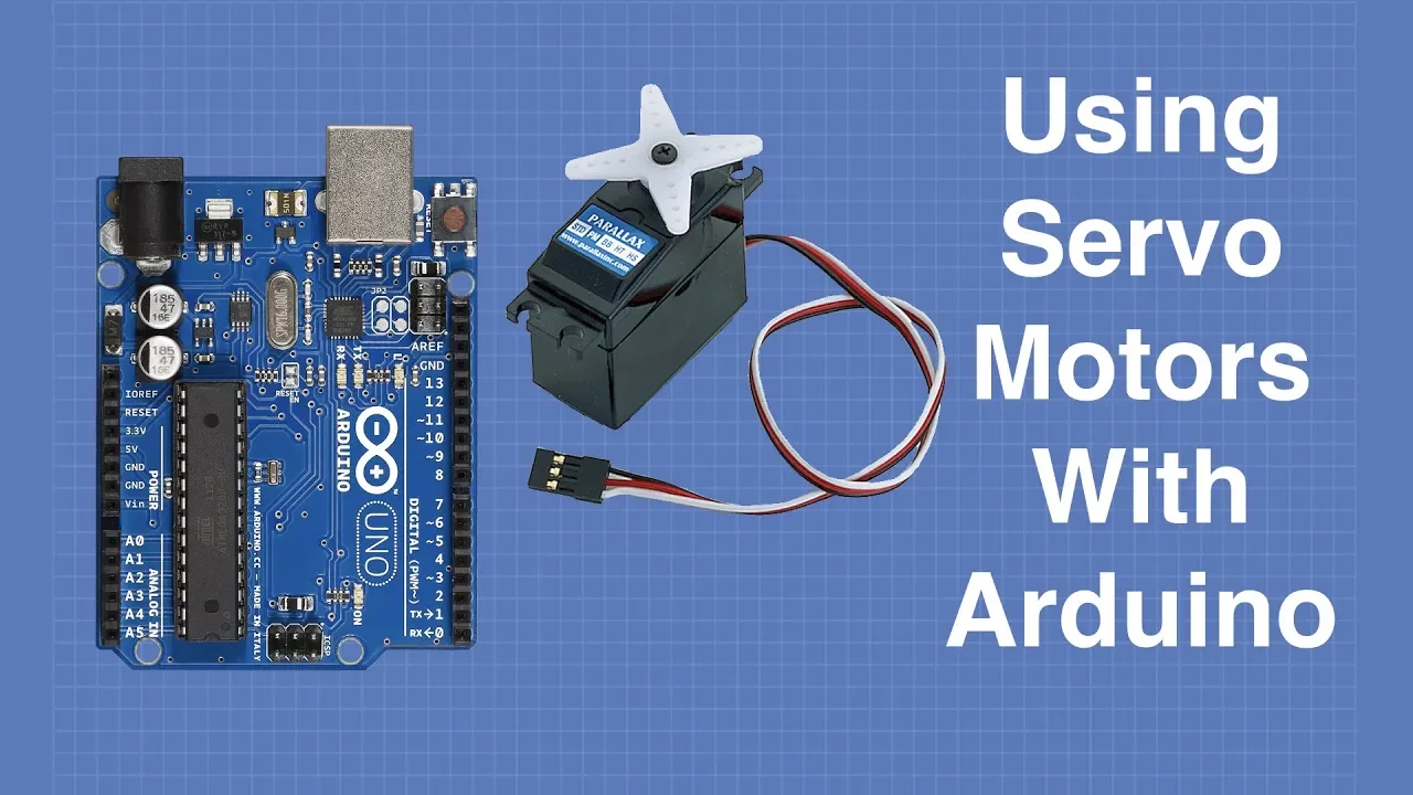


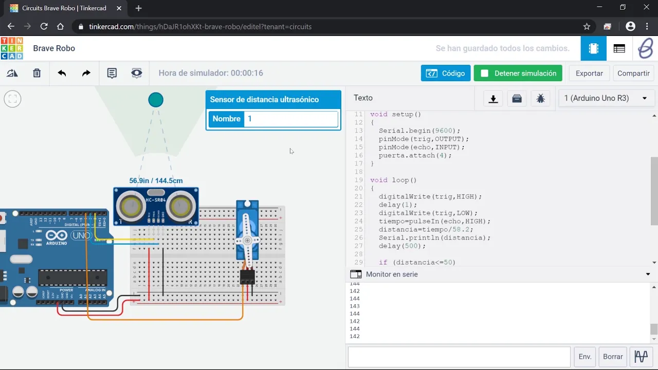




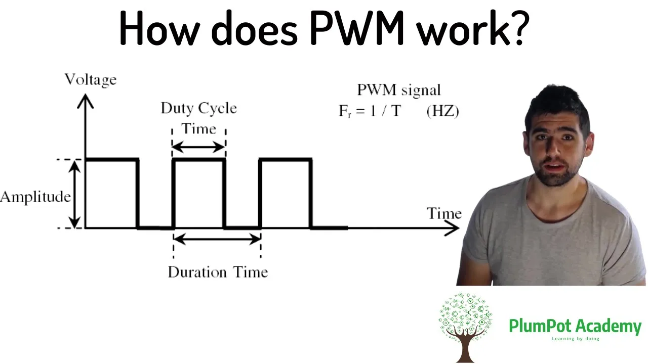
Servo motors are precision devices that use feedback control to rotate to specific angles, controlled by sending PWM (Pulse Width Modulation) signals where the duration of the high pulse determines the position: 1ms for 0°, 1.5ms for 90°, and 2ms for 180°, with the signal period always being 20ms; Arduino provides a built-in Servo library that simplifies this process by handling the timing automatically, allowing users to control servos by calling myservo.attach(pin) to initialize and myservo.write(degree) to set the desired angle, and analog inputs like potentiometers can be used to convert continuous voltage readings into proportional servo positions by mapping the 0-1023 analog range to the 0-180 degree range.
Arduino Servo Motor Control Tutorial: PWM & Potentiometer
Added:Basic Arduino programming fundamentals, including the structure of setup() and loop() functions, and how to upload sketches.
Fundamental concepts of electricity, including voltage, current, ground, and how to safely wire components on a breadboard.
The conceptual definition of Pulse Width Modulation (PWM) and how digital signals can simulate analog outputs.
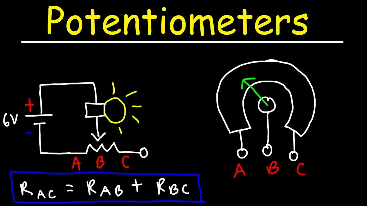
An understanding of analog inputs, specifically how a potentiometer works as a variable voltage divider to output varying voltage levels.
Understanding power budget limitations of the Arduino board and how to safely connect an external power supply to high-current motors.
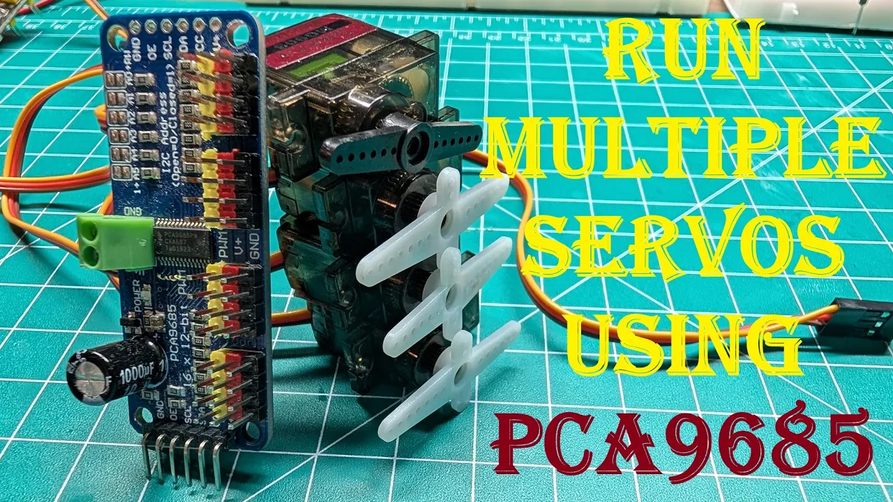
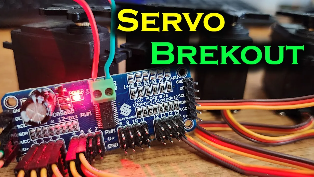
Interfacing with multiple servos simultaneously using dedicated servo driver chips or shields (such as the PCA9685) via I2C communication.
Implementing sensor-driven servo control, such as using ultrasonic sensors or gyroscopes (IMUs) to create self-stabilizing or obstacle-avoiding systems.
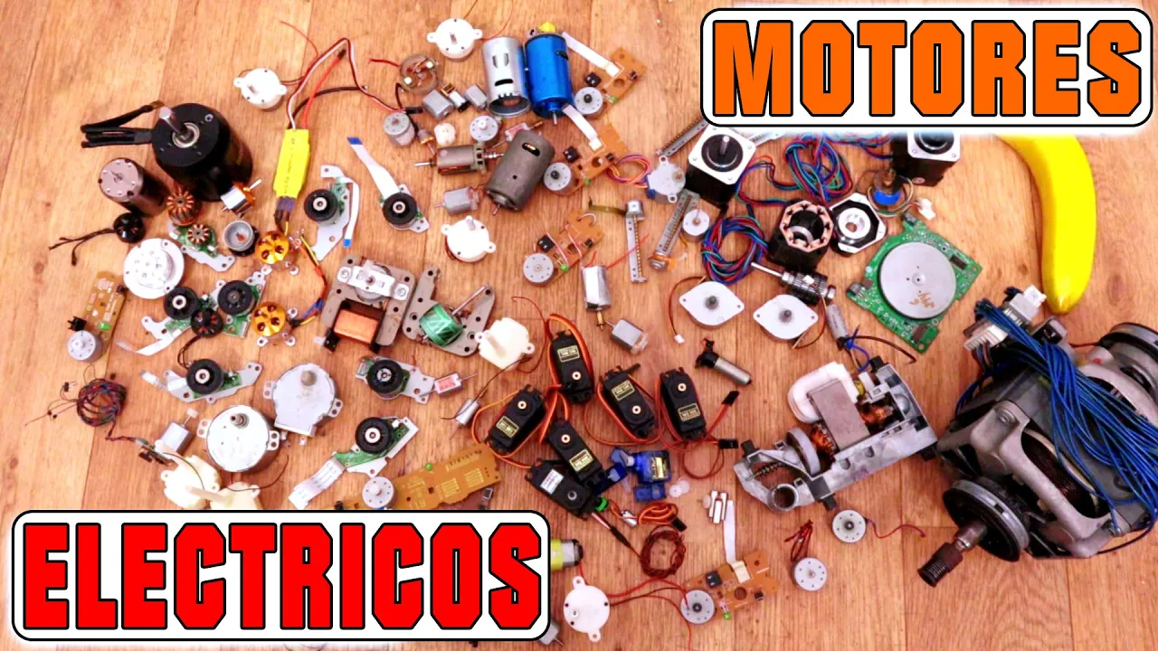
Exploring advanced motor control options, including stepper motors for precise rotational step control and brushless DC (BLDC) motors for high speed.
Coding smooth motion profiles (such as acceleration/deceleration curves or basic PID control) to eliminate jerky servo movements in robotic arms.
17.1K views154likes17:39Original Release: 2019-04-22
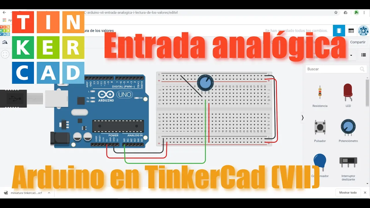
welcome programming knowledge today I'm going to talk about how to control servo okay let's go servo is a device is quite similar with the step motor but it is an exact as the step motor okay this is the inside of civil this is the control circuit it is integrated from each bridge the H bridge either circuit we usually use to control the motor that just a circuit help you open and close the control signal from the microcontroller okay the servo to control the server we will use a PWM to control this circuit to control the control circuit and the control circuit will control the DC motor and potentiometer at the same time to operate the gearbox okay the potentiometer we affected the angle and the DC motor will affect to the speed and the gearbox can up to 60 rpm there are many times of servo but I have some popular server like this first a plosive all this is the cheapest servo and the quality is quite good it can pull about one point a kilogram when we supply it for point a voltage and it can be pull two kilogram when we supply it SiC voltage and this just approximate maybe it can pull 1.5 or Haggar okay because each other approximate the blue the ball can rotate from minus 90 to 90 that's a 180 degrees when you plus at each other and the next it flexible it more expensive a little bit but the quality is more stable any kind of the approximate 200 degrees okay the information estimate with the plausible and the information rating is just approximate and each other theory okay and the last one is mg 996 or this is the most expensive in three times but the quality is good and it can pull stronger when you supply for point evil that is kami pull a kilogram and when and we seek voltage it can be pull 10 kilogram and their ankle also 180 degree there's sometimes about 360 degrees okay but I just you 180 degrees to make an assemble for you and in this video I will use the like civil to make an assemble first of all before we use PWM to control the servo I will create a PWM signal by set hike on low level the digital signal from the I don't know with the function that a delay micro seconds and this either time parameters we will transfer the time parameters right here okay this he house of a walk we use there are is 20 milliseconds if you want your several is wrote a 2-0 decrease this is comedy boom poles you have to make an apple as the digital pins is high in one millisecond and then off its mean make an airport low voltage in the nineteen millisecond left and when you want your zaboor is and the meat is a ninety degree you have to make an apple as the digital beam at one point five millisecond and the other when you change to 180 decrease you have to make an apple is two millisecond at high voltage okay and low voltage a 80 millisecond okay I see how control the servo by the hero signal cannula check the diagram I have diagram right here the servo has three pins the orange is a signal will connect to the p9 you can connect to the tRNAs you type in okay but I will connect to the pin I for the PBM function after that and the meet either red the red is connect to five voltage and the last one II crowd okay let make the circuit I have my civil right here and it's also have three pins orange red and GD is corresponding with signal VCC and GND okay and I have also used three wire as the diagram that is red green and like okay now we'll connect to my server with red EvCC greeny signal and the last one is Gd okay now connect to the eronel signal to p9 v CC v on touch hello last one is GD okay okay before we control I have some code right here these are the code to control the servo by the Ito signal I use pin 9 so I will make the pin eyes as an output nice in the world of function make an eye level at p9 and then D like one milli second but trying and we use microsecond so I will use 1000 right here and then I will make an apple of one touch but right here I have to chain it to 19,000 because my period it 20 millisecond here 20 millisecond 20 millisecond and if I make an apples with high voltage in one millisecond and have to make an Apple phone loved one touch in nineteen second okay and right here in nineteen second okay now let's check ok it's quite brush mark with zero freakery right but sorry it's quite noise and a process month with zero degree so it's can read to hear okay Oh there's something wrong with myself and when I supply is with zero one zero degree I can move it he's quite hard to move okay now I have to change it to one five zero zero he won a fight okay let's check this will rotate to the meat center okay and you see you even move to the center vasee zero decree and the last one will chain - mm and here is a zero okay let's check it would turn to the left okay you see a chain to the left okay okay now we have to control it via PWM and before that we have to know what she analog pins the PWM PC the pins had a to Tobi forest in semo 11 10 9 6 5 3 okay just this bin can use PWM to control the servo and to control the servo I have a server library in idea we have the civil library inside the IDE I don't know you have to move to fascist and assemble services and in selective sweep Pro check ok let's check you have to move to assemble servo and swip ok this is a sample code so now I will use the new diagram ok the new diagram is also as a back with the old diagram I'm soaking is to the pin 9 ok let's check see what happened when I blow the squee project to the aerodrome okay my dough is rotated from the left to right and then from the right to left with my civil on the right is zero decrease and on the left II 180 degree okay remember that just my civil and here it is some code the color here is his turn is wrote a from the zero degree to 180 degree and then is rotated from the a hundred and eighty degree to the zero degree okay this mean is run from the left to Ryan right to left okay it is it right now I have another assemble the co use the potentiometer to control the servo assemble when I turn the potentiometer to left or right the civil will rotate either potentiometer okay let's check the diagram this is the diagram the diagram is I will connect to iron to servo and the left pin potentiometer is five on - and the gene D of civil with the right pin a potentiometer to Cheney and the center pin of potentiometer weakening to a zero to read analog and the signal of civil I will connect to pin night okay let's connect the circuit okay let's check my circuit right here I have three pieces of servo is gonna two three wires okay but five voltage I have to connect to the test more because I just have one father Dutchman I dunno okay and with potentiometer I will use the one kilo ohms okay you can use the other value but from here I will use one kilo ohm okay we will connect to this more okay growl of civil we connect to growl up I don't know and this is a signal of sabor going to be 9 okay now we'll use the yellow were to connect if I wanted to the potentiometer that's either left pins okay and we connect to five voltage here okay now use the orange answer diagram to connect to a zero 30 analog pins okay we're going into a zero and the last one is growl I will connect to the line right pin of potentiometer to growl off I don't know okay and the last one 5 on page two five on touch here okay you can see it okay now I will call some Co for you first the phone I have to check the analog reach from the potentiometer okay and come in it related now use the serial monitor to bring out the volume a potentiometer okay zero dot begin at nine six zero zero by rate okay right here I will bring out I will bring else the value from analog a pin a zero okay okay I will connect my I don't know two laptop and check what's happened this is the okk oh but don't worry about that okay let's check the serial monitor is opened okay this is the value of potentiometer now we turn to left turn to left the variable is increase and maxi about 940 okay the Machine under 40 and the mean is zero okay let's check max again okay Maxie 940 is a gross amount with 1000 intensity okay okay now I have to confess that's where I bow to the decrease we want to control okay I have max II 940 and the degree of us a 180 mus mini zero right and if arrival mini zero okay now we take the nine four zero divided by 180 okay 9 4 0 divide 1 a 0 that about fine okay I will take the integer Phi okay now use fine to multiply the variable to get the control signal I'll use the sweep okay right here I will delete okay do you remember this function is controller servo okay now I will have each for eyeball right here and we put the name is RIT and Allah is from analog pins a zero okay and then convert I have a parabola convert convert okay convert is feet analog divided by Phi okay if I buy fine and then I will transfer the convert here okay now let's check up low let's check myself oh my servo is rotating left right now I will turn the potentiometer to right okay let's see right right right right okay and then try again I would turn to the left laughs laughs laughs laughs okay let's see how I control the servo from the potentiometer you can use this way to control with the other analog device you can reach the analog signal from the other device and then control the servo to do what you want okay thank you for watching the video
Up Next

9:12
Single-Handed Dinghy Tacking: Step-by-Step Sailing Upwind Basics
@sailaboattv
253K views•2017-04-19

178:38
Whole Brain Architecture: First International Workshop 2024
@thewholebrainarchitecturei9784
640 views•2024-07-22
19:52
OpenCV Object Tracking with HSV Color Space | Python Tutorial
@ProgrammingKnowledge
152.5K views•2019-03-31

1:42
Game of Thrones Opening Credits: A Cinematic Analysis
@gameofthrones
46.3M views•2011-04-18
Related Study Plans & Knowledge Roadmaps
Structured learning paths in General & Interdisciplinary Studies
general-studies
Artificial Light: History, Tech & Human Impact
01The Pre-Electric Era: Fire, Oil, and Gas Lighting
02The Incandescent Revolution and Grid Electrification
03Gas Discharge and Fluorescent Illumination
+ 3 more learning modules
14h6 modules
Explore Roadmap
general-studies
Elevator Engineering: History, Physics & Cities
01From Hoists to Safety Brakes: The Dawn of Vertical Lift
02Hydraulic vs. Traction: The Engineering Physics of Elevators
03Modern Speed, Safety, and Algorithms
+ 2 more learning modules
12h5 modules
Explore Roadmap
general-studies
Rubber: Material Science, History & Geopolitics
01Origins of Natural Rubber & Mesoamerican History
02The Chemistry of Natural Rubber & Vulcanization
03The Geopolitics of the Rubber Boom & Colonization
+ 2 more learning modules
12h5 modules
Explore Roadmap
general-studies
Containerization: Evolution, Logistics & Trade
01Ancient Trade & Bulk Cargo: Amphorae to Barrels
02The Industrial Revolution & Cardboard Packaging
03The Containerization Revolution: Malcom McLean
+ 2 more learning modules
12h5 modules
Explore Roadmap