



















The diffraction limit of angular resolution, described by Rayleigh's criterion (θ_min = 1.22λ/D), explains why we initially perceive two headlights as one distant source but distinguish them as separate when the vehicle approaches; this occurs because the angular separation between the sources must exceed the minimum angle determined by the wavelength of light (λ) and the aperture diameter (D) to be resolved as distinct objects.
Why Telescopes Resolve Stars: Wave Optics & Angular Resolution
Added:The wave nature of light, including the concepts of wavelength, frequency, and phase.
The physical phenomenon of wave diffraction, specifically how waves bend and spread when passing through an aperture.
Basic geometric optics, particularly how lenses and mirrors focus light to form images.
The concept of angular measurement in physics and astronomy, including radians, arcminutes, and arcseconds.
The technology of Adaptive Optics, which corrects for atmospheric turbulence to help ground-based telescopes reach their theoretical diffraction limit.
Astronomical Interferometry, which combines signals from multiple telescopes (such as the Event Horizon Telescope) to synthesize a much larger effective aperture.
The engineering and scientific advantages of space-based observatories (e.g., James Webb Space Telescope) in bypassing Earth's atmospheric 'seeing' limitations.
Fourier Optics and advanced image reconstruction techniques, such as deconvolution, used to sharpen diffraction-limited astronomical data.
19.6K views511likes13:05Original Release: 2022-11-09
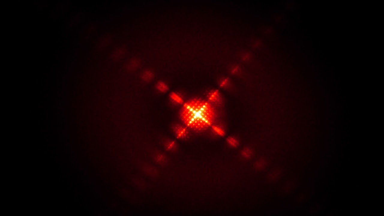
sometimes when we are standing on the side of the road and we observe a headlight from a vehicle which is coming from far away we usually might think oh this could be a two-wheeler because I see only one source of light but as as that vehicle comes closer then you start seeing two headlights or two sources of light instead of one and then you realize oh this is actually a car it's a four wheeler why does this happen why can't we at the very beginning when we first saw the source why can't we then say that it's a four wheeler it's a car because we did learn in Ray Optics we learned in Ray Optics that we get a point image for a point source so if there is a source S1 there will be an image of S1 over here and if there's a source H2 there will be an image of S2 over here just like the two headlights of a car so these two images should be formed on or retina and we should be able to clearly identify that these are two separate sources but we can't do that Ray Optics cannot really explain this but turns out that wave Optics can we will use wave Optics the wave nature of light to explain this and in the process we will also learn about the diffraction limit of angular resolution all right let's begin we know that when light passes through a small opening or an aperture it spreads out it diffracts each point in the opening acts as a secondary source as per the Huygens principle and all of the secondary waves interfere with each other resulting in an interference pattern which can be obtained on a screen this is a pattern when there is a vertical slit when there is a vertical narrow opening there is a central Maxima and then the intensity decreases as you go away further from the center but our eyes they do not have vertical slits we have a circular opening a circular aperture that is called a pupil the pupil is the aperture of our eye through which the light enters even even for cameras the aperture is roughly circular so whenever light enters these circular openings diffraction must also happen here and it does but turns out we do not get a pattern like this if we have a circular opening or a circular aperture the diffraction button let me move this over here the diffraction pattern formed by a circular aperture consists it consists of a central bright spot which is surrounded by a series of bright and dark rings the central bright spot over here this is called an Airy disc now we can describe this pattern in terms of the angle Theta just like how we describe this pattern from a vertical slit in terms of in terms of theta here the angular position of the first minimum that is that is this angle right here this angle Theta is the angle between the first Minima and the center of the central maximum this angle Theta 1 this was given by Lambda divided by a where a was the width of the slit a Lambda is the wavelength of the light here the angle between the center of the central maximum and the first minimum is slightly more just because of the change in the geometry of the slit this is circular and this was vertical this angle the angle between the center of the central maximum and the first minimum this angle is given by Theta this is 1.22 Lambda divided by capital D here capital D is feed diameter of this opening the diameter of this aperture we will not be talking about how we got 1.22 the derivation is a bit complicated will not be going into that but right now we can just accept that this is it is 1.22 Lambda divided by capital D now we get this pattern whenever a light passes through a circular aperture and even Optical instruments Optical instruments can also undergo they can also undergo diffraction for instance a telescope a telescope has an objective lens with very sharp edges at the corners and diffraction can happen at these at these sharp edges so we cannot really ignore the wave nature of light we cannot ignore the effects of diffraction we need to consider that when we are working with Optical instruments like a telescope or a microscope for One Source we see this diffraction pattern but if we have one more Source like the two headlights of a car let's see what do we get then here we have two sources and it could be two distant stars or even the two headlights of a car as the light from these two sources as it passes through through the slit two distinct bright spots two different images can be seen on the screen if no diffraction occurred then we would get two point images on the screen but because diffraction occurs so we get something something like this each Source each source is imaged it is imaged as a bright central region which is surrounded by weaker bright and dark fringes this is what we will see on the screen if we draw the intensity pattern draw the intensity pattern this is what it would look like we have one Maxima over here and the other at some distance over here we see two separate peaks in the resultant which is shown by this dashed line now if the two sources are far enough a far enough apart to keep the central Maxima from overlapping we see that the central Maxima of both the images both the diffraction patterns they aren't overlapping then then we can say that these are two separate sources of light we can easily identify that that is when we say that the images are resolved so in this case we can easily identify that these are two separate sources because the central Maxima of the diffraction patterns they are not at all overlapping each other they are at a good distance apart we can easily tell that these are two separate sources not one so the image here is resolved but if the objects are very close to each other something like something like let's say in this case then these diffraction patterns even they will start coming close to each other so as a result the diffraction pattern on the screen could look like this and if you draw the intensity graph if you try to draw the intensity graph for this diffraction pattern that could look somewhat somewhat like this these diffraction patterns they start overlapping the two central Maxima overlap in this case instead of 2 we will see only one source and you can see that in the form of the resultant the dashed line we will see only one Peak so we don't see two Central bright spots we see only one so it appears to us that there aren't two objects there's only one object in this case we say that the image is not resolved it's unresolved because we cannot distinguish we cannot separate out we cannot Identify two separate objects for us they are just one object there is a condition when the images are said to be just resolved so if you have two sources and the distance between these two sources is slightly less compared to the first case but slightly more compared to the last case here the diffraction pattern will be closer to each other compared to the first case and the pattern could look somewhat like this by looking at the image we can say that these are two separate sources of light the image is just just resolved the right amount now to tell whether the two images are just resolved the condition is whenever the central maximum of one image when it falls on the first minimum when it falls on the first minimum of another image then the images are said to be just resolved this limiting condition of resolution is called release Criterion this is when the limit of resolution has been reached the objects cannot be closer to each other than this otherwise then we won't be able to resolve them and we would just see them as one source so what is the minimum separation that we can have and here I'm talking about the minimum angular separation I'm talking about this I'm talking about this angle right here Theta let's call it Theta min Theta minimum we know that for all circular apertures the angular separation between the center of the central maximum and the first minimum is 1.22 Lambda divided by D so this distance right here this is 1.22 Lambda divided by capital D you can see that is the angular separation between the center of the central maximum and the first minimum so this is 1.22 Lambda by D so if we draw if we draw this pattern over here this is how it could look like the center of one diffraction pattern or one image it coincides or falls on the minimum of the second diffraction pattern or the second image and this distance is the angular distance this is the angle and this is 1.22 Lambda y capital D the angular separation of the images is the same as the angular separation of the objects so this Theta Min this is also equal to 1.22 Lambda by capital D this is the minimum angle that the two sources can make at the slit so that the two sources are just resolved so the release Criterion of resolution is that your separation and we are talking about angular separation here the separation between the two sources of light the two starts or two or the two headlights should be equal to or more than 1.22 Lambda by D if it is less than that then we won't be able to resolve it into two separate objects this is what we call the diffraction limit on angular resolution this is the diffraction limit on angular resolution now let's see what is the angular resolution of our eye let's say that light of wavelength 500 nanometers let's take some average wavelength 500 nanometers it enters a human eye of and the diameter of the pupil the diameter of the pupil we can take that we can take that as on average we can take that as 2 millimeters so the limit of angular resolution this angle is 1.22 into Lambda divided by capital D and when we work this out this comes out to be 1.22 into 500 into 10 to the power minus 9 divided by 2 into 10 to the power -3 this is when you work this out this is 3 into 10 to the power minus 4 radians now to get a better feel for this let's change radius to degrees and we can do that by multiplying this number with 180 divided by 3.14 so when we do that this is 3 into 10 to the power minus 4 into 180 divided by 3.14 and this is 0.018 degrees this is a very small number so coming back to our original question of the two headlights the reason why we see one source when the headlights are far apart from our eye we see them as one source is that the two sources they must be making they must be making an angle Which is less than less than 0.018 degrees this angle will be less than this angle right here so we cannot separate the two sources we identify them as only one but when the light sources they come closer to the eye this angle you can see the the value of this angle is slightly increasing and maybe at this point this is how the headlights look like we are just able to resolve that these are two separate sources this this is not just one source over here we can say the angle would be equal to Theta Min this would be equal to 0.018 degrees that is the angle that the two sources are making at the eye and when when these sources are closer to the eye now they are making a big enough angle if we can clearly very clearly see that these are two separate sources you can imagine that if if these two sources S1 S2 let's say though if these two sources are distant stars then they would be making an extremely ridiculously small angle at the aperture so we use telescopes to resolve that and how do telescopes help for telescopes the aperture this B is extremely large this is extremely large that really decreases this angle Theta Min can be very small so this means that telescope can very finely resolve two distinct objects even when they are making a very small angle at the aperture this Theta Theta mean is very small for telescopes that's how telescopes can resolve distant distant objects
Up Next

10:16
Two-Telescope Optical Interferometer Architecture Explained
@FrantzMartinache
12.1K views•2017-06-23

12:53
21cm Hyperfine Transition in Neutral Hydrogen: Radio Astronomy Basics
@AaronRobertParsons
12.4K views•2011-10-13

32:32
NMR Spin Physics I: Zeeman Effect, Resonance Condition & Larmor Frequency
@nptel-indianinstituteofsci8064
2.3K views•2024-01-17

27:14
Entropy and the Second Law of Thermodynamics Explained
@veritasium
27.5M views•2023-07-01
Related Study Plans & Knowledge Roadmaps
Structured learning paths in Physics
physics
Nuclear Physics (Decay, Fission & Reactors)
01Atomic Structure and the Binding Force
02Radioactive Decay and Half-Life
03Nuclear Fission Mechanics and Chain Reactions
+ 2 more learning modules
12h5 modules
Explore Roadmap
physics
Soft Matter (Polymers, Colloids & Rheology)
01Foundations of Soft Matter & Thermal Forces
02Polymer Physics and Macromolecules
03Colloids, Surfactants, and Self-Assembly
+ 2 more learning modules
38h5 modules
Explore Roadmap
physics
Analytical Mechanics: Lagrangian & Hamiltonian
01Mathematical Foundations: Calculus of Variations
02From Newtonian Mechanics to Constraint Dynamics
03The Principle of Least Action & Lagrangian Mechanics
+ 3 more learning modules
28h6 modules
Explore Roadmap
physics
General Relativity (Spacetime & Cosmology)
01Foundations of Relativity: Special Relativity
02The Geometry of Spacetime: Equivalence Principle & Curvature
03Einstein's Field Equations: The Mathematics of Gravity
+ 2 more learning modules
55h5 modules
Explore Roadmap